Graph Transformation in a Nutshell
Reiko Heckel
1 Department of Computer Science University of Leicester, United KingdomAbstract
Even sophisticated techniques start out from simple ideas. Later, in reply to application needs or theoretical problems new concepts are introduced and new formalisations proposed, often to a point where the original simple core is hardly recognizably. In this paper we provide a non-technical introduction to the basic concepts of typed graph transformation systems, completed by a survey of more advanced concepts, and explain some of its history and motivations.
Keywords: rule-basad graph transformation, typed attributed graphs, application conditions and constraints, control conditions, multi objects
1
Introduction
Graphs and diagrams provide a simple and powerful approach to a variety of problems that are typical to computer science in general, and software en-gineering in particular. In fact, for most activities in the software process, a variety of visual notations have been proposed, including state diagrams, Structured Analysis, control flow graphs, architectural description languages, function block diagrams, and the UML family of languages. These notations produce models that can be easily seen as graphs and thus graph transfor-mations are involved, either explicitly or behind the scenes, when specifying how these models should be built and interpreted, and how they evolve over time and are mapped to implementations. At the same time, graphs provide a universally adopted data structure, as well as a model for the topology of
1 Email: [email protected]
1571-0661/$ – see front matter © 2006 Elsevier B.V. All rights reserved.
www.elsevier.com/locate/entcs
object-oriented, component-based and distributed systems. Computations in such systems are therefore naturally modelled as graph transformations, too. Graph transformations have originally evolved in reaction to shortcom-ings in the expressiveness of classical approaches to rewriting, like Chomsky grammars and term rewriting, to deal with non-linear structures. The first proposals, appearing in the late sixties and early seventies [10,11], are con-cerned with rule based image recognition, translation of diagram languages, etc.
In this paper, we first introduce the basic concepts of graph transformation systems. Section 3 provides a high-level survey of more advanced concepts, and Section 4 gives references for further reading.
2
The Basic Approach
Modelling can be described as a two-dimensional abstraction process. The first dimension consists in building models as representations of reality. The sec-ond dimension isgeneralisation, i.e., the extraction of concepts from concrete objets, or of rules from observed behaviour. We will deal with generalisation first, reserving representation issues for Sect. 2.2.
2.1 Modelling by Example
It is a matter of philosophical debate if generalisations exist in reality or if, e.g., the concept of car as generalisation of individual cars is part of the human perception of the world. Avoiding this discission, we will illustrate two forms of generalisation by means of a simple video game ofPacMan, for didactic purposes playing the role of “reality”. Later, the insights gained from this example shall be transferred to the graph-based representation to explain some of the elementary concepts of graph transformation.
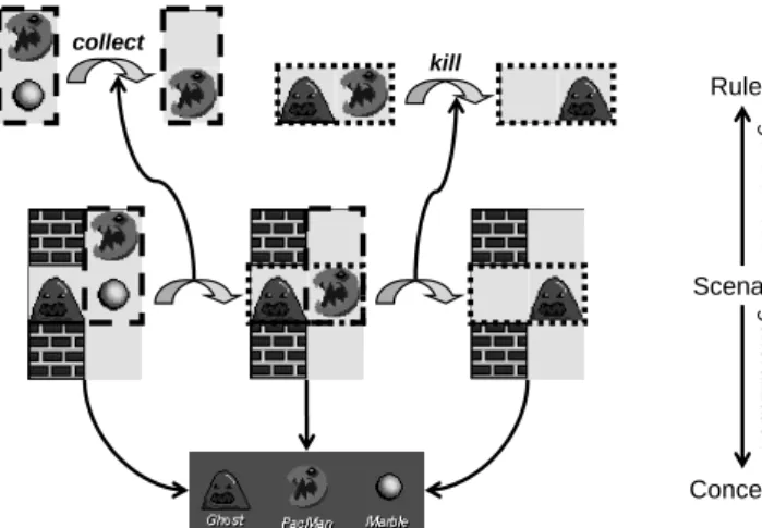
Figure1 exemplifies both conceptual and behavioural generalisation. Our observation of the game is represented by the scenario in the middle of the figure in three successive snapshots. Conceptual generalisation extracts three types of characters, PacMan, Ghost, and Marble shown in the bottom, each of which has several instances in the scenario. This conceptual generalisation and the corresponding relation between a concept (type) and its instances is the first basic idea.
From the observed transformations,behavioural generalisation extracts the rules in the top, encapsulating the changes from one snapshot to the next. Rules can be derived systematically by determining their scope in the trans-formation and cutting off (abstracting from) the irrelevant context. For the
collect kill Rules Concepts Scenario gener ali z at ion gener ali z at ion
Fig. 1. From snapshots and scenarios to concepts and rules
rules collect and kill in the top of the figure, their scope is given by the areas in the dashed and dotted boxes, respectively.
The actual game, from which the snapshots are taken, has been produced using the StageCast visual programming environment for video games. The environment evolved out of a didactic experiment on teaching the basics of programming to children from the age of 7. The idea of extracting rules as general behaviour descriptions from sample state transformations is called
programming by example and represents the main didactic tool of the Stage-Cast environment. It also provides a perfect example of the second basic idea of graph transformation: the definition of rules as specifications of state transformations.
In the following, we shall turn back to the first dimension of modelling, transferring the generalisations described above from “reality” to its repre-sentation in a model. We will use graphs as means to represent snapshots, concepts, and rules—the third basic idea of the approach.
2.2 Type and Instance Graphs
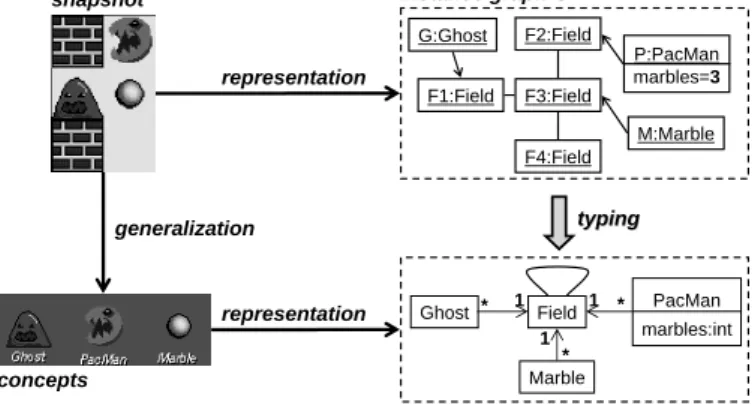
Graphs provide the most basic mathematical model for entities and relations. A graph consists of a set of vertices V and a set of edges E such that each edge e inE has a source and a target vertex s(e) andt(e) in V, respectively. Like the graph Gin the upper right of Fig. 2, graphs can represent snapshots by modelling concrete entities as vertices and relations between theses entities as edges. In our model, verticesP:PacMan, G:Ghost M:Marble represent the corresponding characters in the snapshot. Another type of vertex is used to represent fields, i.e., the open spaces in the snapshot where characters can be located. Edges represent the current location of characters as well as the
instance graph G type graph TG typing typing Field PacMan marbles:int Ghost Marble 1 1 1 * * * G:Ghost F1:Field F4:Field F2:Field F3:Field M:Marble P:PacMan marbles=3 representation snapshot generalization representation concepts
Fig. 2. Type and instance graph of the PacMan example
neighbourhood relation of fields.
In modelling the snapshot we have implicitly assumed that vertices have a type, like F1 to F4 having type F ield. The type of a vertex (or an edge) represents the conceptual generalisation of the corresponding real-world entity. Like an individual snapshot, also a collection of interrelated concepts may be represented as a graph. Figure 2 in the bottom right shows an example of a type graph representing the conceptual structure of the PacMan game and providing the types for the instance graph in the top.
The relation between concepts and their occurrences in snapshots is for-mally captured by the notion oftyped graphs: A fixedtype graphT Grepresents the type (concept) level and itsinstance graphs the individual snapshots. This distinction is a recurring pattern, like in class and objects, data base schema and states, XML schema and documents, etc.
We use the notation of class and object diagrams in the Unified Modelling Language (UML) to visualise type and instance graphs and their relationship, i.e., o:C represents a vertexo (an object) of type C (a class). In addition to vertices and edges, graphs may contain attributes to store values of pre-defined data types. In our example, this notion is used to represent the number of marbles PacMan has collected before the current snapshot. Also attributes have a type-level declarationa :T, where a is the name of the attribute and T is the data type, and an instance-level occurrence a= v where attribute a is assigned value v.
The relation between type and instance level is subject to the usual com-patibility conditions, i.e.,
• for each vertex o : C in the instance graph there must a vertex type C in the type graph;
corre-G:Ghost F1:Field F4:Field F2:Field F3:Field M:Marble P:PacMan marbles=3 G:Ghost F1:Field F4:Field F2:Field
F3:Field marbles=4:PacMan
G:Ghost F1:Field F4:Field F2:Field F3:Field collect kill typing typing Field PacMan marbles:int Ghost Marble 1 1 1 * * * typingtyping typi ng typi ng G1 G0 G2 TG
Fig. 3. From scenarios to rules: graph representation
f1:Field f2:Field p:PacMan f1:Field f2:Field p:PacMan movePM(p) p:PacMan marbles=m f1:Field f2:Field :Marble f1:Field f2:Field p:PacMan marbles=m+1 collect(p)
Fig. 4. Rules for PacMan
sponding edge type in the type graph between vertex types C1 and C2;
• for each attribute value a=v associated with a vertexo:C in an instance graph, there must be a corresponding declaration a : T in vertex type C such that v is of data type T;
2.3 Rules and Transformations
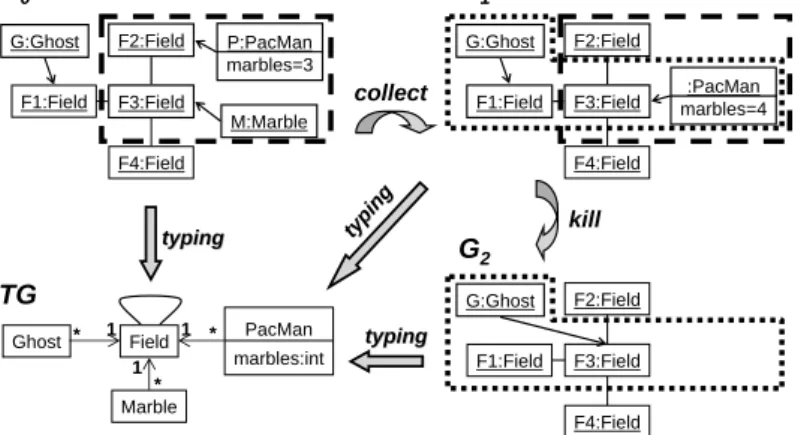
Having represented snapshots as instance graphs over a type graph built as a representation of the game’s concepts, we are turning to the genuine core of the approach: the specification of instance graph transformations by means of rules. Following the idea of extracting rules from transformation scenarios, Fig. 3 shows a graph representation of the behavioural generalisation illus-trated in the upper part of Fig. 1.
The generalisation is achieved by focussing on the relevant subgraph in the source state and observing its changes in the target state. But besides cutting off context, we also abstract from the concrete attribute values replacing, e.g., 3 in G0 bymand 4 in G1 by m+ 1. The resulting rules are shown in the top
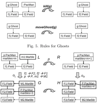
of Fig. 4 and 5, with the rules for moving PacMan andGhost in the bottom. More formally, fixing a type graph T G, a graph transformation rule p :
f1:Field f2:Field g:Ghost f1:Field f2:Field g:Ghost moveGhost(g) g:Ghost f1:Field f2:Field :PacMan f1:Field f2:Field g:Ghost kill(g)
Fig. 5. Rules for Ghosts
F1:Field
F2:Field marbles=3P:PacMan
M2:Marble oL G L p R p:PacMan marbles=m f1:Field f2:Field m1:Marble f1:Field f2:Field p:PacMan marbles=m+1 F3:Field M1:Marble oR P:PacMan marbles=4 H F1:Field F2:Field M2:Marble F3:Field f1ÆF2, f2ÆF1 pÆP, m1ÆM1
Fig. 6. Transformation step using rulecollect
L → R consists of a name p and a pair of instance graphs over T G whose structure is compatible, i.e., vertices with the same identity in Land R have the same type and attributes, and edges with the same identity have the same type, source, and target. The left-hand side L represents the pre-conditions of the rule while the right-hand side Rdescribes the post-conditions.
But rules do also have a constructive meaning, besides being generalisa-tions of transformageneralisa-tions. They generate transformations by replacing in a given graph an occurrence of the left-hand side with a copy of the right-hand side. Thus, a graph transformation from a pre-state G to a post-state H, denoted byG=p(⇒o) H, is performed in three steps.
(i) Find an occurrence oL of the left-hand sideL in the given graphG. (ii) Delete from G all vertices and edges matched byL\R.
(iii) Paste to the result a copy ofR\L, yielding the derived graphH. In Fig.6 the occurrence oL of the rule’s left-hand side is indicated next to the left downward arrow. The variablemrepresenting the value of the marble attribute before the step, is assigned value 3. The transformation deletes the edge fromPacMan P to FieldF2, because it is matched by the edge from f1 to p in L, which does not occur in R. The same applies to the value 3 of the
marbles attribute of vertexP. To the graph obtained after deletion, we paste a copy of the edge from p to f2 in R. The occurrence oL tells us where this edge must be added, i.e., to the images of p and f2, P and F1, respectively.
a:A
a:A b:B
?
?
a1:A
a:A
?
?
a2:A a1:A
Fig. 7. More difficult examples
At the same time, the new attribute value marbles = 3 + 1 = 4 is computed from the memorised old value m= 3.
However, this is not the only possibility for applying this rule. Another option would be to map f1 → F2, f2 →F3, p→ P, m→ M2, collecting the lower marble instead. Also, we could have chosen to apply themovePM rule. That means, there are two causes of non-determinism: choosing the rule and the occurrence at which it is applied.
The total behaviour of ourPacMangame is given by the set of all sequences of consecutive transformation steps G0 p=1(⇒ · · ·o1) p=n(⇒on) Gn using the rules of the game and starting from a valid instance graph G0. As a simple example, we recall the two-step sequence in Fig.3 which is re-generated by application of the two previously extracted rules. Note that all graphs of a sequence must be valid instances of the fixed type graph T G.
The example of Fig. 6 is not entirely representative of the problems that may be caused by deleting elements in a graph during step 2. In fact, we have to make sure that the remaining structure G\o(L\R) is still a graph, i.e., that no edges are left dangling because of the deletion of their source or target vertices. The problem is exemplified in its simplest form by the step in Fig. 7 on the left. A related problem is depicted on the right, where we observe a conflict between deleting vertex a:Aas required by a1 :A and preserving it as suggested by a2 :A.
In both cases, there exist a radical and a conservative solution: The first gives priority to deletion, deleting the vertex along with the dangling edge in the left example and vertexain the right example of Fig.7. Both may lead to surprising and undesired effects and may require additional control to restrict rule applications to the intended cases.
The safer alternative consists in formulating standard applications condi-tions which exclude the depicted situacondi-tions as valid transformacondi-tions. This is achieved by the gluing conditions of the algebraic (or double-pushout) ap-proach to graph transformation, which provides the basis for the presentation in this text.
g:Ghost
f:Field p:PacMan
Fig. 8. A graphical constraint
3
Advanced concepts
The phenomenon of “dangling edges” is caused by the fact that a node in a graph may, in general, have an unknown number of connections. This is in contrast with, e.g., the rewriting of strings where the linear structure provides exact information about the connections of any substring. The additional complication has led to a number of extensions of the basic approach, some of which shall be discussed below.
3.1 Constraints
One way of solving the problem is to constrain the number of connections. However, type graphs are not expressive enough to define such restrictions. For example, in order to model the PacMan game board it makes sense to require that each Ghost, Pacman, or Marble vertex is linked to exactly one
Field vertex. Such constraints need to be expressed by additional cardinality annotations as shown in the type graph of Fig.2.
More complex constraints could deal with the (non-) existence of certain patterns, including paths, cycles, etc. They can be expressed in terms of logic formulae or as graphical constraints. An example for the latter is given in Fig.8. The constraint expresses by means of a forbidden subgraph that there must not be a Ghost and a PacMan situated at the same Field. In order to satisfy the constraint, a graphGmust not contain a subgraph isomorphic to it. In first order logic, the same property could read¬∃g:Ghost;p:P acM an;f : F ield. at(g, f)∧at(p, f).
Constraints restrict the set of admissible instance graphs and can be used to control the transformation process by ruling out transformations leading to non-admissible graphs. This is comparable to the integrity mechanism in a data base management system which checks the validity of constraints after each update, but before the new state is committed.
3.2 Multi-objects
Also more complex operations, like “delete all Ghosts located on Fields di-rectly reachable from PacMan’s current position”, can only be specified in
f2:Field f2:Field g:Ghost
f1:Field f2:Field f1:Field f2:Field g:Ghost
superPM
F1:Field
F2:Field marbles=P:PacMan3
F3:Field G1:Ghost G2:Ghost F3:Field G3:Ghost oL= {f1ÆF2, pÆP, f2Æ{F1, F3}, gÆ{G1, G2} } F1:Field
F2:Field P:PacManmarbles=3
F3:Field
F3:Field G3:Ghost
p:PacMan p:PacMan
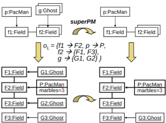
Fig. 9. Rule application with multi object
the presented approach if the number of reachable fields is known in advance. This is not the case in our example. Thus, for expressing such universally quantified operations, we have to adopt the additional concept ofmulti object
from UML object diagrams.
A multi object like f2 in the rule of Fig. 9 stands for the maximal set of objects that have the specified connections to the fixed objects in the rule, in our case all the neighbouring fields of the matchF2 off1. Similarly,g:Ghost stands for all ghosts inG located at these fields. The example shows that the universal quantification extends smoothly to the actions of the rule, i.e., the deletion of the ghosts.
3.3 Application conditions
Generalizing the pre-defined gluing conditions of the algebraic approach, user defined application conditions are used, for example, to ”sense” the existence or non-existence of connections in the vicinity of the occurrence of the rule’s left hand side. Figure10shows an improved rulemovePM checking that there is no marble in the place PacMan is moving to. Graphically, this is indicated by the crossed out vertex in the left-hand side.
Intuitively, the rule is applicable at an occurrence if this cannot be extended to the forbidden elements. That means, the applicability does not only depend on the graphG, but also on the chosen occurrence, as indicated in the figure.
3.4 Control conditions
Beside extensions that restrict the applicability of individual rules, global con-trol structures lead toprogrammed graph transformations. Here, rules embed-ded them into imperative programming constructs or a visual control flow language, as shown in Fig. 11 where UML activity diagrams are used to
ex-oL= {f1ÆF2, f2ÆF1, pÆP} violates application condition oL= {f1ÆF2, f2ÆF3, pÆP} satisfies application condition f1:Field f2:Field p:PacMan f1:Field f2:Field p:PacMan movePM :Marble F1:Field
F2:Field marbles=3P:PacMan
F3:Field
M1:Marble oL
Fig. 10. Rule application with negative application condition
[success]
collect(p)[failure] movePM(p)
[success]
kill(p) [failure]moveGhost(g) Behavior(p:PacMan) : Behavior(g:Ghost) :
Fig. 11. Controlling rules by activity diagrams
press, respectively, the order of rule applications to individual PacMan and Ghost vertices.
Special conditions[failure] and[success]are introduced to make the control flow dependent of the (non-)applicability of rules. Another notable feature is the possibility of passing parameters to rules. In our example it is intended that, e.g., the order of collect and movePM operations is understood locally for any individual PacMan vertex.
4
Further Reading
Fundamental approaches to graph transformation [12] include the algebraic or double-pushout (DPO) approach [6], the node-label controlled (NLC) [9] approach, and the Progres approach [13] which represents the first major application of graph transformation to software engineering [7].
The simple core model introduced in Section 2 is based on (a set-theoretic presentation of) the double-pushout approach [6]) whose features are common to most graph transformation approaches. Generally, we distinguish two fun-damentally different views of graph transformation referred to as the gluing and the connecting approach. They differ for the mechanism used to embed the righthand side of the rule in the context (the structure left over from the given graph after deletion): In a gluing approach like DPO, the new graph is formed by gluing the right-hand side with the context along common vertices. In a connecting approach like NLC, the embedding is realised by a disjoint
union, with as many new edges as needed to connect the right-hand side with the rest of the graph.
This feature, which provides one possible answer to a fundamental prob-lem, the replacement of substructures in an unknown context, is known in software engineering-oriented approaches by the name of set nodes or multi objects, e.g., Progres[13,14], a language and tool for PROgrammed Graph REwriting Systems, and Fujaba [1], an environment for round trip engi-neering between UML diagrams and Java based on graph transformation as computational model.
Both approaches have extended the basic approach by programmed trans-formations, concerned with controlling the (otherwise non-deterministic) rewrite process, as well as application conditions, restricting the applicability of in-dividual rules, as well as structural constraints over graphs, comparable to invariants or integrity constraints in data bases, deal with the (non-) existence of certain patterns, including paths, cycles, etc. They are expressed as car-dinalities, in terms of first- or higher-order logic, or as graphical constraints. The latter are also supported by AGG [8], which implements the algebraic approach by means of a rule interpreter and associated analysis techniques.
For recent surveys on graph transformations and its applications see the handbooks [12,4,5] the survey paper [2] and the tutorial paper [3].
References
[1]From UML to Java and Back Again: The Fujaba homepage,www.upb.de/cs/isileit.
[2] Andries, M., G. Engels, A. Habel, B. Hoffmann, H.-J. Kreowski, S. Kuske, D. Plump, A. Sch¨urr and G. Taentzer,Graph transformation for specification and programming, Science of Computer Programming34(1999), pp. 1–54.
URLhttp://www.elsevier.com/cas/tree/store/scico/sub/1999/34/1/559.pdf
[3] Baresi, L. and R. Heckel,Tutorial introduction to graph transformation: A software engineering perspective, in: A. Corradini, H. Ehrig, H.-J. Kreowski and G. Rozenberg, editors,Proc. of the First International Conference on Graph Transformation (ICGT 2002), Barcellona, Spain, LNCS2505(2002), pp. 402–429.
URLhttp://www.elet.polimi.it/upload/baresi/pub/papers/ICGT.pdf
[4] Ehrig, H., G. Engels, H.-J. Kreowski and G. Rozenberg, editors, “Handbook of Graph Grammars and Computing by Graph Transformation, Volume 2: Applications, Languages, and Tools,” World Scientific, 1999.
[5] Ehrig, H., H.-J. Kreowski, U. Montanari and G. Rozenberg, editors, “Handbook of Graph Grammars and Computing by Graph Transformation, Volume 3: Concurrency and Distribution,” World Scientific, 1999.
[6] Ehrig, H., M. Pfender and H. Schneider, Graph grammars: an algebraic approach, in: 14th Annual IEEE Symposium on Switching and Automata Theory (1973), pp. 167–180.
[7] Engels, G., R. Gall, M. Nagl and W. Sch¨afer,Software specification using graph grammars, Computing31(1983), pp. 317–346.
[8] Ermel, C., M. Rudolf and G. Taentzer, The AGG approach: Language and tool environment, in: Engels et al. [4] pp. 551 – 601.
[9] Janssens, D. and G. Rozenberg, On the structure of node-label controlled graph grammars, Information Science20(1980), pp. 191–216.
[10] Pfaltz, J. L. and A. Rosenfeld,Web grammars, Int. Joint Conference on Artificial Intelligence (1969), pp. 609–619.
[11] Pratt, T. W., Pair grammars, graph languages and string-to-graph translations, Journal of Computer and System Sciences5(1971), pp. 560–595.
[12] Rozenberg, G., editor, “Handbook of Graph Grammars and Computing by Graph Transformation, Volume 1: Foundations,” World Scientific, 1997.
[13] Sch¨urr, A.,Programmed graph replacement systems, in: Rozenberg [12] pp. 479 – 546. [14] Sch¨urr, A., A. Winter and A. Z¨undorf,The PROGRES approach: Language and environment,