FANs 930, 930.5, 125, 121 Product/Technical Bulletin A350
Issue Date 0614
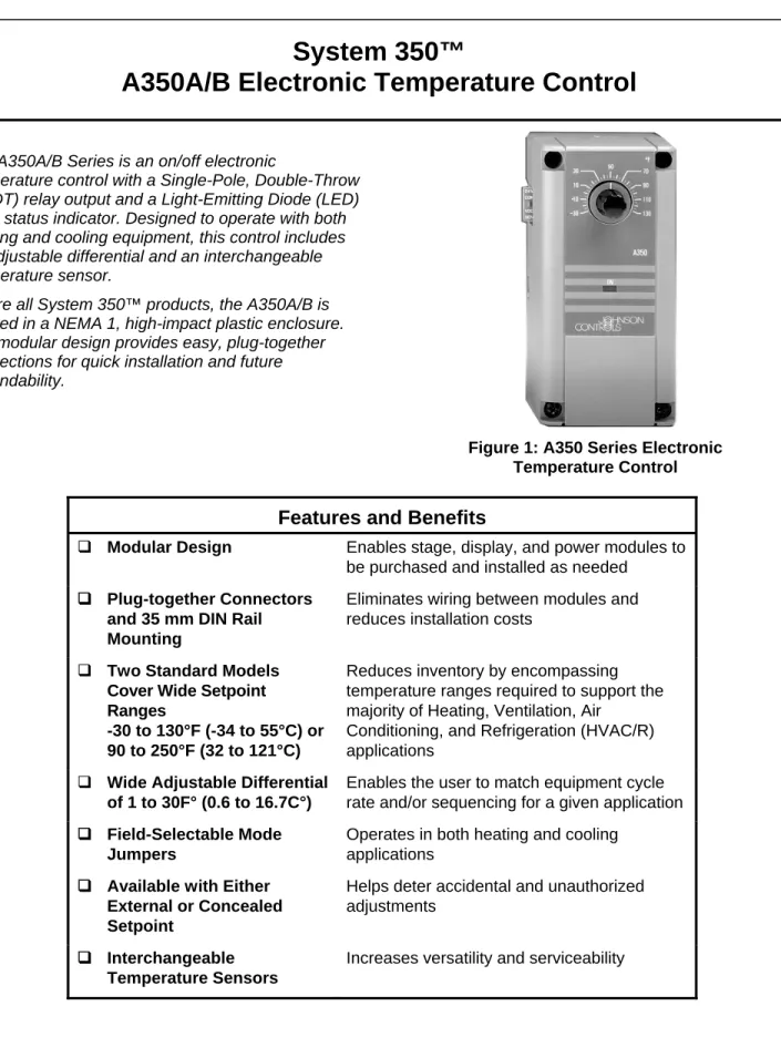
The A350A/B Series is an on/off electronic
temperature control with a Single-Pole, Double-Throw (SPDT) relay output and a Light-Emitting Diode (LED) relay status indicator. Designed to operate with both heating and cooling equipment, this control includes an adjustable differential and an interchangeable temperature sensor.
As are all System 350™ products, the A350A/B is housed in a NEMA 1, high-impact plastic enclosure. The modular design provides easy, plug-together connections for quick installation and future expandability.
Figure 1: A350 Series Electronic Temperature Control
Features and Benefits
Modular Design Enables stage, display, and power modules to be purchased and installed as needed
Plug-together Connectors and 35 mm DIN Rail
Mounting
Eliminates wiring between modules and reduces installation costs
Two Standard Models Cover Wide Setpoint Ranges
-30 to 130°F (-34 to 55°C) or 90 to 250°F (32 to 121°C)
Reduces inventory by encompassing temperature ranges required to support the majority of Heating, Ventilation, Air
Conditioning, and Refrigeration (HVAC/R) applications
Wide Adjustable Differential of 1 to 30F° (0.6 to 16.7C°)
Enables the user to match equipment cycle rate and/or sequencing for a given application Field-Selectable Mode
Jumpers
Operates in both heating and cooling applications
Available with Either Helps deter accidental and unauthorized
System 350™
A
pplication
The A350A/B Temperature Control can be used as a standalone device or in conjunction with other System 350 plug-together modules to control single or multiple-stage HVAC or refrigeration equipment. Typical applications include:
frozen/refrigerated food cases
cooling tower control
beverage/milk coolers
chiller staging
space temperature controlA typical System 350 Temperature Control arrangement includes the following:
A350A/B Temperature Control
S350 Stage Modules
D350 Digital Temperature Sensor/Setpoint Display Module
Y350R Power Module (or Class 2 24 VAC transformer)
A99B Series Temperature SensorIMPORTANT: Use this A350A/B Electronic Temperature Control only as an operating control. Where failure or malfunction of the A350A/B control could lead to personal injury or property damage to the controlled equipment or other property, additional precautions must be designed into the control system. Incorporate and maintain other devices, such as supervisory or alarm systems or safety or limit controls, intended to warn of or protect against failure or malfunction of the A350A/B control.
IMPORTANT: Utiliser ce A350A/B Electronic Temperature Control uniquement en tant que dispositif de régulation. Lorsqu'une défaillance ou un dysfonctionnement du
A350A/B control risque de provoquer des blessures ou d'endommager l'équipement contrôlé ou un autre équipement, la conception du système de contrôle doit intégrer des dispositifs de protection
supplémentaires. Veiller dans ce cas à intégrer de façon permanente d'autres dispositifs, tels que des systèmes de supervision ou d'alarme, ou des dispositifs de sécurité ou de limitation, ayant une fonction d'avertissement ou de protection en cas de défaillance ou de dysfonctionnement du
O
peration
The A350A/B Temperature Control operates on 24 VAC and provides an SPDT relay output. A front panel LED lights to indicate when the relay is energized. Adjustable features include:
setpoint
differential
heating/cooling modeIMPORTANT: All System 350 Controls are designed for use only as operating controls. Where an operating control failure would result in personal injury and/or loss of property, it is the responsibility of the installer to add devices (safety, limit controls) that protect against, or systems (alarm, supervisory systems) that warn of, control failure.
Setpoint Adjustment
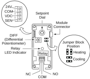
Setpoint is defined as the temperature at which the A350A/B’s relay de-energizes. Use the Setpoint Dial on the front of the A350A/B to adjust setpoint. See Figure 2.
Differential Adjustment
Differential is defined as the change in sensor temperature between energization and
de-energization of the relay. Adjustment of the A350A/B differential is made using the potentiometer marked DIFF. See Figure 2 for its location. Refer to Table 5 for adjustment ranges. Relay Module Connector Relay LED Indicator Setpoint Dial DIFF (Differential
Potentiometer) Jumper Block
Position Heating Cooling 24V COM VDC SEN NC NO
Figure 2: A350A/B Board Layout and Terminal Locations
Heating/Cooling Mode Adjustment
With Heating mode selected, the differential is below setpoint. The relay and LED indicator will de-energize as the temperature rises to the setpoint. As the
temperature drops to the setpoint minus the differential setting, the relay will energize and the LED illuminates. Refer to Figure 6.
With Cooling mode selected, the differential is above setpoint. The relay and LED indicator will de-energize as the temperature drops to setpoint. As the
A
dd-On Modules
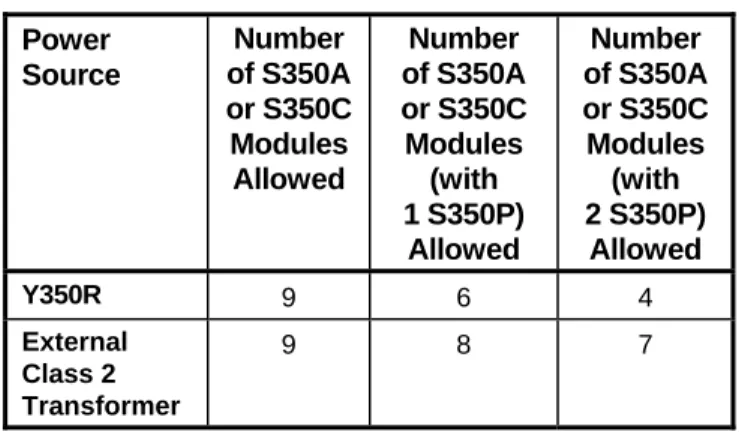
The S350 Stage Modules, D350 Digital Temperature Display Module, and Y350R Power Module connect together and plug into the A350 via a connector on its right side. The maximum number of add-on modules is listed in Table 1.
Table 1: Maximum Number of S350 Stage
Modules per A350A/A350B
Power Source Number of S350A or S350C Modules Allowed Number of S350A or S350C Modules (with 1 S350P) Allowed Number of S350A or S350C Modules (with 2 S350P) Allowed Y350R 9 6 4 External Class 2 Transformer 9 8 7
Note: For each S350P added, the number of S350A or S350C Stage Modules that can be used with a Y350R decreases by two. If an external transformer is used, the number of S350A and S350C Stage Modules used decreases by one for each additional S350P.
S350A On-Off Stage Modules
S350A On-Off Stage Modules receive power, setpoint, and sensor input from the A350 control. S350A Stage Modules perform switching functions based upon the A350’s setpoint and sensor information, with the offset and differential selected at the S350A.
For more information on these modules, refer to the
System 350 S350 Temperature, S351 Humidity, and S352 Pressure On/Off Stage Modules
Product/Technical Bulletin (LIT-930080).
S350C Slave Stage Modules
S350C Slave Stage Modules receive power and sensor input from the A350 control. S350C Slave Stage Modules perform switching functions based upon the A350’s sensor information. (Setpoint and differential are selected independently at the S350C.) For more information on these modules, refer to the
System 350TM S350C Temperature Slave Stage Module Product/Technical Bulletin (LIT-930084).
S350P Proportional Stage Modules
S350P Proportional Stage Modules receive power, setpoint, and sensor input from the A350 control. The S350P responds with an analog 0-10 VDC and 0-20 mA output signal. This is based upon the A350’s setpoint and sensor information, with the offset, throttling range, and minimum output selected at the S350P.
For more information on these modules, refer to the
System 350TM S350P Proportional Plus Integral Temperature Stage Module Product/Technical Bulletin (LIT-930086).
D350 Temperature Sensor/Setpoint
Display Module
The D350 receives power, sensor, and setpoint information from the A350. A 3-digit Liquid Crystal Diode (LCD) gives continuous read-out of the sensed temperature. Pushing the PRESS FOR SETPOINT button on the front of the D350 causes the setpoint of the adjoining A350 to be displayed.
Y350R Power Module
The Y350R provides a convenient method of powering System 350 modules from a 120 or 240 VAC power source. The Y350R supplies power to the modules. See Figure 5 for a typical wiring diagram where a Y350R is used to power the A350.
For more information on this module, refer to
System 350TM Y350R Power Module Product/Technical Bulletin (LIT-930090).
D
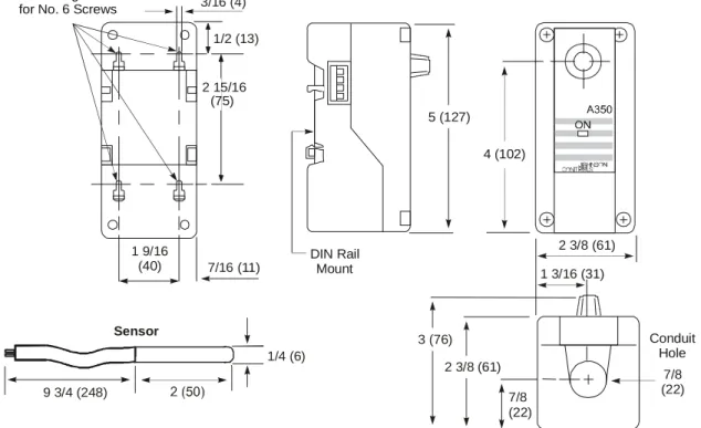
imensions
Mounting Slots for No. 6 Screws
DIN Rail Mount Conduit Hole (75) 3/16 (4) 1/2 (13) 2 15/16 1 9/16 (40) 2 3/8 (61) 1 3/16 (31) 7/8 (22) 7/16 (11) 9 3/4 (248) Sensor 1/4 (6) 7/8 (22) 3 (76) 2 3/8 (61) 5 (127) 4 (102)
I
nstallation and Wiring
The A350A/B Temperature Control is housed in a compact NEMA 1 plastic enclosure designed for standard 35 mm DIN rail mounting. The A350A/B is not position sensitive but should be mounted for convenient wiring and adjustment. Four key-slot mounting holes on the back of the control case are provided for surface mounting. Add-on modules must plug into the right side of the A350A/B control.
Note: When mounting the System 350 modules to rigid conduit, attach the hub to the conduit before securing the hub to the control enclosure.
!
WARNING: Risk of Electric Shock.Disconnect the power supply before making electrical connections. Contact with components carrying hazardous voltage can cause electric shock and may result in severe
personal injury or death. AVERTISSEMENT:Risque de décharge
électrique.
Débrancher l'alimentation avant de réaliser tout branchement électrique. Tout contact avec des composants porteurs de tensions dangereuses risque d'entraîner une décharge électrique et de provoquer des blessures graves, voire mortelles.
All wiring must conform to the National Electrical Code and/or local regulations.Note: For maximum electrical rating of control, see label inside the control cover or Specifications
section. Use copper conductors only.
Consult the typical wiring diagrams (Figures 4 and 5) for proper wiring and terminal designations.A350A/B S350A D350 Sensor Load Load L L 24 VAC 1 1 2 2 24V COM VDC SEN
Note: If sensor is mounted less than 50 ft (15.2 m) from the A350A/B, shielded cable is not required.
Figure 4: Typical Wiring Diagram for A350A/B Powered by an External 10 VA Transformer
Sensor Connection
Shielded cable is not generally required for sensor wiring on runs of less than 50 ft (15.2 m), but is recommended for lengths greater than 50 ft (15.2 m). When using shielded cable, isolate and tape the shield at the sensor. Connect the shield to the COM sensor terminal on the A350A/B. (See Figure 2 for terminal location.) The A99BA-200C sensor, which includes shielded cable, is available if needed.
Note: At the maximum cable lengths listed in Table 2, no more than 1F° (0.6C°) error in the sensed temperature will result due to wire resistance.
Table 2: Recommended Maximum Sensor
Cable Lengths
Wire Shielded Cable Length*
Gauge Feet Meters
14 AWG 800 244
16 AWG 500 152
18 AWG 310 94
20 AWG 200 61
22 AWG 124 38
Various A99B Series Temperature Sensors and mounting hardware are available for use with A350 Series Controls. See Tables 3 and 6. The sensor must be connected to the COM and SEN terminals on the four-position terminal strip located at the top left of the printed circuit board (Refer to Figures 2, 4, and 5.). The sensors are not polarity sensitive.
The sensor must be mounted so that it can accurately sense the temperature of the controlled medium.
Table 3: Sensors Included With A350A/B
Controls
Control Sensor Included
Sensor lead length is 9-3/4 in. (0.25 m) A350AA-1C A99BB-25C; Range: -40 to 212°F
(-40 to 100°C)
A350AA-2C A99BC-25C; Range: -40 to 248°F (-40 to 120°C)
A350AA-3C A99BB-25C; Range: -40 to 212°F (-40 to 100°C)
A350AB-1C No Sensor Included A350AB-2C No Sensor Included A350AB-5C No Sensor Included
A350BA-1C A99BB-25C; Range: -40 to 212°F (-40 to 100°C)
A350BA-2C A99BC-25; Range: -40 to 248°F (-40 to 120°C)
A350BB-1C No Sensor Included
For more information regarding sensor options and installation, refer to the A99B SeriesTemperature Sensors Product/Technical Bulletin (LIT-125186).
A350A/B S350A S350A S350A D350
Load Load Load Load
Y350R
120 VAC
Shield (Connect to COM on A350)
A
djustments
Follow this procedure to set up the A350A/B for the desired operation.
1. Remove the A350 cover by loosening the four captive cover screws.
2. Set the heating/cooling jumper blocks to the desired mode of operation. Position the jumper blocks vertically for heating or horizontally for cooling. (See Figure 2.)
IMPORTANT: Verify that the heating/cooling jumper blocks are in the proper position before powering the System 350 modules. If the jumper blocks on the control or staging modules are installed in the wrong position, the device will activate the relay in response to the opposite signal. The heating or cooling equipment will remain energized until the error is corrected.
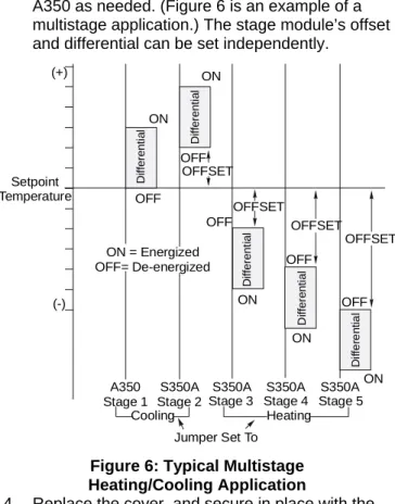
3. Adjust the differential potentiometer (DIFF) on the A350 as needed. (Figure 6 is an example of a multistage application.) The stage module’s offset and differential can be set independently.
ON OFF Di ffe re n ti a l ON OFF S350A Stage 2 A350 Stage 1 Setpoint Temperature (+) (-) Di ffe re n ti a l ON OFF D iffe re n ti a l ON OFF S350A Stage 4 S350A Stage 3 D if fer en ti al ON OFF Di ffe re n ti a l ON = Energized OFF= De-energized Stage 5 S350A Heating Cooling Jumper Set To OFFSET OFFSET OFFSET OFFSET
Figure 6: Typical Multistage
Note: The A350A/B setpoint is factory calibrated at midscale to a tolerance of +/- 1F° (0.6C°). Setpoint tolerance at the extreme ends of the setpoint ranges in relation to the printed scale can be +/- 3F° (1.7C°). The D350 Display Module is unaffected by this tolerance shift. Use the D350 for the most accurate setpoint selection.
C
heckout P
rocedureFollow this procedure to verify that the A350A/B is connected and functioning properly.
1. Make sure installation and wiring connections are according to job specifications before applying power. (Refer to Figure 6 for an example of a multistage application.)
2. Make the necessary adjustments and electrical connections.
3. Put the system in operation and observe at least three complete operating cycles before leaving the installation.
T
roubleshooting
If the control system does not function properly, verify that the proper mode is selected on each module (Heat/Cool, Direct Acting/Reverse Acting). Proceed as follows to determine the cause of the problem:
1. Make sure proper voltage is applied to the A350 control.
a. Connect a digital voltmeter (DVM) between the 24V and COM terminals located on the control’s left side terminal block (See Figure 2.)
If an external transformer is used, select AC volts on the DVM and verify that the voltage is between 20 and 30 VAC.
If a Y350R Power Module is used, select DC volts on the DVM and verify that the voltage is between 16 and 38 VDC.
b. If the DVM reading is within the indicated voltage range, proceed to Step 2.
c. If the DVM reading is not within the indicated voltage range, correct the wiring, replace the Y350R, or replace the external transformer.
2. Check temperature sensor for proper resistance. a. Take an accurate, independent temperature
reading at the sensor location.
b. Disconnect the sensor from the control. Using an ohmmeter, measure the resistance across the two sensor leads. Consult Figure 7 to verify sensor conformance.
°F Temperature 260 240 220 200 180 160 140 120 100 80 60 40 20 0 -20 -40 500 700 900 1100 Resistance (Ohms) 1300 1500 1700 1900 2100 °C 120 100 80 60 40 20 0 -20 -40
Figure 7: Temperature vs. Resistance Chart for the A99B Series Sensor c. If the resistance varies substantially from the
optimal resistance for that temperature, the sensor or wiring must be replaced.
Note: The sensor reading indicated by the D350 may differ from thermometer readings due to sensor tolerances, time constants, accuracy of
thermometer, and other factors.
3. Check the A350 for proper operation. Note: Steps 1 and 2 must be performed first.
a. Adjust the setpoint dial to at least 40°F (22°C) below the sensor temperature determined in Step 2.
b. Increase setpoint by slowly turning the dial until the control relay and LED turn On and Off.
c. If the relay does not perform as indicated in Table 4, replace the A350.
Table 4: A350 Relay Troubleshooting
Action LED N.O. Contact Status
Setpoint Dial Setting*
Heating On Closed (Ts) = Sp - Diff
Heating Off Open (Ts) = Sp
Cooling On Closed (Ts) = Sp + Diff
Cooling Off Open (Ts) = Sp
*(Ts) is sensed temperature, and (Sp) is setpoint temperature.
R
epairs and Replacement
Do not make field repairs or perform calibration. Replacement controls and A99B Temperature Sensors are available through the nearest Johnson Controls representative. See Tables 5 and 6 for ordering information.
O
rdering
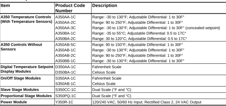
Table 5: System 350 Products
Item Product Code
Number
Description
A350 Temperature Controls (With Temperature Sensors)
A350AA-1C A350AA-2C A350AA-3C A350BA-1C A350BA-2C
Range: -30 to 130°F; Adjustable Differential: 1 to 30F° Range: 90 to 250°F; Adjustable Differential: 1 to 30F°
Range: -30 to 130°F; Adjustable Differential: 1 to 30F° (concealed setpoint) Range: -35 to 55°C; Adjustable Differential: 0.5 to 17C°
Range: 30 to 120°C; Adjustable Differential: 0.5 to 17C° A350 Controls Without
Sensors
A350AB-5C A350AB-1C A350AB-2C
Range: 90 to 150°F; Adjustable Differential: 1 to 30F° Range: -30 to 130°F; Adjustable Differential: 1 to 30F° Range: 90 to 250°F; Adjustable Differential: 1 to 30F°
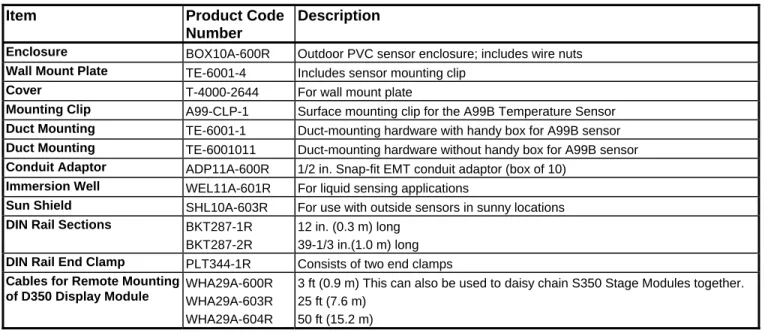
Table 6: System 350 Accessories
Item Product Code
Number
Description
Enclosure BOX10A-600R Outdoor PVC sensor enclosure; includes wire nuts
Wall Mount Plate TE-6001-4 Includes sensor mounting clip
Cover T-4000-2644 For wall mount plate
Mounting Clip A99-CLP-1 Surface mounting clip for the A99B Temperature Sensor
Duct Mounting TE-6001-1 Duct-mounting hardware with handy box for A99B sensor
Duct Mounting TE-6001011 Duct-mounting hardware without handy box for A99B sensor
Conduit Adaptor ADP11A-600R 1/2 in. Snap-fit EMT conduit adaptor (box of 10)
Immersion Well WEL11A-601R For liquid sensing applications
Sun Shield SHL10A-603R For use with outside sensors in sunny locations
DIN Rail Sections BKT287-1R
BKT287-2R
12 in. (0.3 m) long 39-1/3 in.(1.0 m) long
DIN Rail End Clamp PLT344-1R Consists of two end clamps
Cables for Remote Mounting of D350 Display Module
WHA29A-600R WHA29A-603R WHA29A-604R
3 ft (0.9 m) This can also be used to daisy chain S350 Stage Modules together. 25 ft (7.6 m)
50 ft (15.2 m)
S
pecifications
Product A350A/B Electronic Temperature Control
Supply Voltage Y350R Power Module: Input: 120/240 VAC 50/60 Hz
Output: 24 VDC, unfiltered, 10 VA, Class 2 External Source: 24 VAC, 50/60 Hz Class 2 (20-30 VAC) Note: Only one supply voltage source may be used.
Power Consumption 1.4 VA
Ambient Temperatures Operating: -30 to 150°F (-34 to 66°C) Shipping: -40 to 185°F (-40 to 85°C)
Humidity 0 to 95% RH non-condensing; maximum dew point: 85°F (29°C) Setpoint Adjustment Range See Table 5.
Differential Adjustment Range See Table 5.
SPDT Relay Output 120V 208 to 240V
Horsepower: 1/2 1/2
Full Load: 9.8A 4.9A
Locked Rotor: 58.8A 29.4A Non-Inductive: 10A at 24 to 240 VAC Pilot Duty: 125 VA at 24 to 240 VAC Sensor Replaceable positive temperature coefficient sensor
Reference resistance: 1035 ohms at 77°F (25°C) Material Case and cover: NEMA 1 high-impact thermoplastic Agency Listings UL Listed, CCN XAPX, File E27734
UL Listed for Canada, CCN XAPX7, File E27734
The performance specifications are nominal and conform to acceptable industry standards. For application at conditions beyond these specifications, consult Johnson Controls Application Engineering at 1-414-524-5535. Johnson Controls, Inc. shall not be liable for damages resulting from misapplication or misuse of its products.