The design, fabrication, and application of microthermal sensors are presented in this work. The working principle of the microthermal sensor is thermistor, using platinum as the sensing material. A new mesh-membrane structure is presented. This design can reduce the etching time and still provide stiff-enough suspension. The fabrication of the mesh-membrane is timesaving and wastes less material because the back-side etching processes are avoided. The fabricated thermal sensor has flat surface, a sensitivity of 3.2638CrmW, and a response time of less than 5 ms. In addition, one-wire type thermal flow sensors based on this kind of microthermal sensor are designed and fabricated. For the flow velocity higher than 1.5 mrs, the sensitivity of the flow sensor operating in the constant-voltage mode is
Ž .y1r2 Ž .y1r2
above 0.01433 mA mrs , with power consumption of 14.56 mW, and is above 7.98 mV mrs in the constant-current mode, with power consumption of 45.10 mW.q2000 Elsevier Science S.A. All rights reserved.
Keywords: Thermal sensors; Flow sensors
1. Introduction
Microsensors fabricated by CMOS technology and sili-con micromachining are widely developed, owing to the development of semiconductors and MEMS technology. There are many advantages of microsensors, such as high precision, small size, low power consumption, high sensi-tivity, and batch production. Thermal sensors are one sort of microsensors. A thermal sensor measures the physical quantities by transducing them into thermal quantities first and then further into electrical quantities. Therefore, ther-mal sensors are the key components of many microsensors,
w x w x
such as flow sensors 1–9 , IR sensors 10,11 , humidity
w x w x
sensors 12 , vacuum gauges 13,14 , thermal
accelerome-w x
ters 15 , etc.
)
Corresponding author. Tel.: q886-3-574-2923; fax: q 886-3-572-2840.
Ž .
E-mail address: [email protected] W. Fang
Conventionally, the sensing principles of thermal
sen-w x
sors are classified into three types: thermistors 4,12 ,
w x w x
thermocouples 2,9,11,13–15 , and transistors 16,17 . The structures of thermal sensors are classified into four types:
w x w x
closed membrane 5–7,10 , floating membrane 8,12,18 ,
w x w x
cantilever 3,9 , and bridge 3,5,9 . The selection of the sensing principle and the structure of thermal sensors depends on their applications. There are some disadvan-tages of existing thermal sensors. The closed membrane structure needs a double-side fabrication process, wastes more material and is time-consuming. The floating mem-brane structure needs long and thin cantilever beams to suspend the membrane. Such structures cost more etching time and have less active area. The cantilever-type of thermal sensor has unwanted out-of-plane deformation be-cause of residual stresses and also costs more etching time. The bridge-type thermal sensor has less active area and may buckle when subjected to large compressive residual stresses.
The goal of this work is to develop a new membrane-structure thermal sensor which has simple fabrication pro-cesses and good performances. In addition, these thermal
0924-4247r00r$ - see front matterq2000 Elsevier Science S.A. All rights reserved.
Ž .
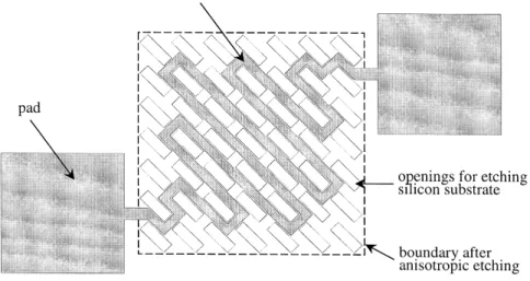
Fig. 1. The design of a thermal sensor with the mesh-membrane supporting structure.
sensors are applied to flow velocity measurement. The measurement results will be described and discussed.
2. Design and fabrication
In regard to the supporting structure of thermal sensors, this research developed a new mesh-membrane instead of the four existing structures. Fig. 1 shows the design of the mesh-membrane structure. The etching openings of the membrane lead to undercutting the silicon substrate. This design can reduce the etching time and still provide stiff-enough suspension. The fabrication of the mesh-membrane is timesaving and wastes less material because the back-side etching processes are avoided. The working principle of
Fig. 2. The schematic diagram of the fabrication processes.
the thermal sensor is thermistor, using platinum as the sensing material.
The main fabrication processes are illustrated in Fig. 2.
˚
First, a 2000-A-thick LPCVD silicon rich nitride was Ž . deposited and patterned using RIE as shown in Fig. 2 a
Ž .
and b . The shape of the mesh-membrane was thus de-fined. The silicon rich nitride has high strength and its low residual tensile stress made the membrane flat. A thin Ti
˚
film of about 200 A, used as a barrier layer, and a thin Pt,
˚
the thermistor material, film of about 1800 A was de-posited with E-Gun evaporation and patterned with the
Ž . Ž .
lift-off approach as illustrated in Fig. 2 c and d . Finally, the mesh-membrane was released from its underlying
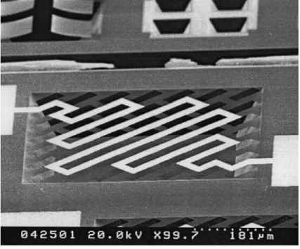
sili-Ž . con substrate by KOH etching as shown in Fig. 2 e . Fig. 3 shows the SEM photograph of a typical fabrication thermal sensor. The membrane is 600=600=0.2mm in size. As demonstrated by the fabrication processes, the proposed designs are simple and have high yield.
3. Measurement and results
Four characteristics of the thermal sensors were mea-sured: the flatness of the sensor surface, the temperature
Ž .
coefficient of resistance TCR , sensitivity, and response time. The objective of these tests is to confirm the quality of the thermal sensors. The measurements were made in a windless room at room temperature.
The surface profile of the sensors was characterized by interferometer profilometry. The maximum vertical deflec-tion from the silicon substrate to the mesh-membrane is about 280 nm. Obviously, the present mesh-membrane structure has a flat surface. Fig. 4 shows the resistance changes of the thermal sensor against temperature. The
Ž .
TCR of thermistor is 0.00249 1r8C , determined with linear curve fitting from 308C to 6008C. As a comparison, Ž . w x the TCR of the bulk material is 0.00392 1r8C 19 .
Fig. 3. The SEM photograph of the fabricated thermal sensor.
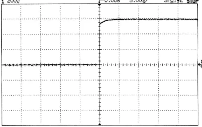
Fig. 5 shows the relation between the temperature rise of the thermal sensor and the power supplied. Using linear curve fitting, the average sensitivity of the thermal sensors is 3.2638CrmW. The thermal sensor was indicated from the test results to have high thermal isolation. Fig. 6 shows that the response time of the thermal sensor is about 5 ms. The output voltage was measured in a constant 18.07 mA current.
The above results show that the present thermal sensor has a flat surface, high reappearance, high linearity, high thermal isolation, and a short response time. With these good characteristics, the present thermal sensors can be applied to many areas. In the following, we exhibit its application to flow velocity measurement.
Fig. 4. The resistance changes of the thermal sensor against temperature.
4. Application — flow velocity measurement
4.1. The principle of flowÕelocity sensing
To measure the flow velocity, a heat source and thermal sensors are required. The heat is carried away from the source when the flow passes over. The larger the flow velocity is, the more heat will be carried away. In a one-wire type flow sensor, the heat source and thermal sensor are identical. When electric power is applied in a stagnant condition, the temperature of the sensor surface increases. With flow passing over, the heat is carried away to lead to reduction of temperature and resistance. By detecting the resistance change with electrical circuits or electrical instruments, the flow-induces temperature change of the thermal sensor can be measured. Since the
tempera-Fig. 5. The temperature rises of the thermal sensor against power supplied.
Fig. 6. The history of the output voltage of the thermal sensor.
ture change increases with increasing velocity, the flow velocity can be correlated with the resistance change.
4.2. Experimental setup
The experimental setup is schematically shown in Fig. 7. The air flow produced by an air compressor passes through a condenser for humidity reduction. A surge tank is used to prevent fluctuation of the flow rate. The flow
Ž
sensor is mounted on a glass plate 0.5 mm thick, 100 mm .
wide, and 300 mm long and is located at the exit of a flow channel. This channel is designed to provide uniform air flow. In this case, the heat transfer is regarded as the
Ž .
forced convection. A hot wire anemometer TSI-ISA100 is used to measure the flow velocity at the channel exit. Flow velocity is sensed in both the constant-voltage mode Ž2 or 4 V and the constant-current mode 12.96 or 23.08. Ž
.
mA . In the constant-voltage mode, the resistance of the thermal sensor decreases with increasing flow velocity because of temperature decrease. According to the Ohm law, VsI=R, the output current increases with the flow
Fig. 7. The experimental setup for flow velocity measurement.
velocity. Similarly, the constant-current mode the resis-tance of the thermal sensor decreases with flow velocity, and so does the output voltage.
4.3. Measurement results and discussions Ž .
Fig. 8 a shows the relation between the current change and the flow velocity when the sensor operates in the
Ž .
constant-voltage mode. Fig. 8 b shows the relation be-tween the voltage change and the flow velocity when the sensor operates in the constant-current mode. Owing to the limitation of the facility, the maximum air velocity avail-able was only 11 mrs. For low velocities, the output behaves in the opposite way as we expected. As in Fig.
Ž .
Fig. 8. The results of flow velocity measurement: a constant-voltage
Ž .
sensor is subjected to a slow gas flow. The reasons for this unexpected phenomenon are not clear. A possible explana-tion is discussed as follows. Under a stagnant condiexplana-tion, a stable temperature of the sensor surface can be reached with upward heat transfer through natural convection. In the presence of a weak horizontal flow, the flow pattern is somewhat deflected downstream and the heat transfer is in a mode of mixed natural and forced convection. If the flow is so slow that a part of the heat generated in the leading part of the sensor accumulates in the trailing part of it. The cavities in the mesh-membrane help to trap the flow and enhance the accumulation. Therefore, the rate of heat transfer by the mixed convection is less than that by natural convection. In other words, the mean surface tem-perature, which the output corresponds to, is higher with a weak flow. The special phenomenon is consequently ob-served. When the flow velocity is large, forced convection dominates and the heat can be effectively carried down-stream. The temperature of the sensor surface simply decreases with increasing flow velocity. Further study is necessary to obtain the definite explanation and detailed insight associated with this phenomenon.
It should pointed out that the quantities of flow velocity is less reliable for flow velocity lower than 1.5 mrs, owing to the corresponding large uncertainties of the hot wire anemometer. Table 1 lists the sensitivity and the power consumption of the flow sensor for velocities larger than 1.5 mrs in different working voltages and currents.
5. Conclusions
The design, fabrication, tests, and application of thermal sensors with a mesh-membrane structure are presented in this work. Compared with the traditional membrane struc-tures, the mesh-membrane structure has simpler fabrication processes. It was proved to have a flat surface, high reappearance, high sensitivity, high linearity, good thermal isolation, and a short response time. This one-wire type thermal sensor was applied as a flow sensor, which exhib-ited high sensitivity, and low power consumption. For flow
45.10 mW.
Acknowledgements
The authors would like to appreciate the Department of Electrical Engineering, National Tsing Hua University, the Semiconductor Center of National Chiao Tung University, and the National Nano Device Laboratory in providing the fabrication facilities. The authors would also like to thank Prof. R.-S. Huang for his valuable suggestions.
References
w x1 T.S.J. Lammerink, N.R. Tas, M. Elwenspoek, H.J.J. Fluitman,
Mi-Ž .
cro-liquid flow sensor, Sens. Actuators, A 37–38 1993 45–50. w x2 D. Moser, R. Lenggenhager, G. Wachutka, H. Baltes, Fabrication
and modeling of CMOS microbridge gas flow sensors, Sens.
Actua-Ž .
tors, B 6 1992 165–169.
w x3 G. Wachutka, R. Lenggenhager, D. Moser, H. Baltes, Analytical 2D-model of CMOS micromachined gas flow sensor, in: The 6th International Conference on Solid-State Sensors and Actuators
ŽTransducer ’91 , San Francisco, CA, June, 1991, 1991, pp. 22–25.. w x4 T. Neda, K. Nakamura, T. Takumi, A polysilicon flow sensor for
Ž .
gas flow meter, Sens. Actuators, A 54 1996 626–631.
w x5 D. Moser, H. Baltes, A high sensitive CMOS gas flow sensor on a
Ž .
thin dielectric membrane, Sens. Actuators, A 37–38 1993 33–37. w x6 D. Moser, R. Lenggenhager, H. Baltes, Silicon gas flow sensors using industrial CMOS and bipolar IC technology, Sens. Actuators,
Ž .
A 25–27 1991 577–581.
w x7 U. Dillner, E. Kessler, S. Poser, V. Baier, J. Muller, Low power consumption thermal gas-flow sensor based on thermopiles of highly
Ž .
effective thermoelectric materials, Sens. Actuators, A 60 1997 1–4.
w x8 F. Mayer, G. Salis, J. Funk, O. Paul, H. Baltes, Scaling of thermal CMOS gas flow microsensors: experiment and simulation, in: Pro-ceeding of the IEEE Micro Electro Mechanical Systems, San Diego, CA, Feb., 1996, 1996, pp. 116–121.
w x9 F. Mayer, G. Salis, J. Funk, O. Paul, H. Baltes, Scaling of thermal CMOS gas flow microsensors: experiment and simulation, in: Pro-ceeding of the IEEE Micro Electro Mechanical Systems, San Diego, CA, Feb., 1996, 1996, pp. 116–121.
based on AlGaAs–GaAs micromachining, Sens. Actuators, A 46–47
Ž1995 432–436..
w12 M. Kimura, Absolute-humidity sensing independent of the ambientx
Ž .
temperature, Sens. Actuators, A 55 1996 7–11.
w13 A.W. Van Herwaarden, D.C. Van Duyn, J. Groeneweg, Small sizex vacuum sensors based on silicon thermopiles, Sens. Actuators, A
Ž .
25–27 1991 565–569.
w14 A. Mzerd, F. Tcheliebou, A. Sackda, A. Boyer, Improvement ofx thermal sensor based on Bi Te , Sb Te , and Bi2 3 2 3 0.1Sb1.9Te , Sens.3
Ž .
Actuators, A 46–47 1995 387–390.
w15 U.A. Dauderstadt, P.H.S. De Vries, R. Hiratsuka, J.G. Korvink,x ¨ P.M. Sarro, H. Baltes, S. Middelhoek, Simulation aspects of a
Ž .
thermal accelerometer, Sens. Actuators, A 55 1996 3–6. w16 G.C.M. Meijer, K. Vingerling, Measurement of the temperaturex
Ž .
dependence of the I Vc be characteristics of integrated bipolar
tran-Ž .
sistors, IEEE J. Solid-State Circuits SC-15 1980 237–240. w17 G.C.M. Meijer, Thermal sensor based on transistors, Sens. Actuatorsx
Ž .
10 1986 103–125.
w18 Y.M. Chen, J.S. Shie, T. Hwang, Parameter extraction of resistivex
Ž .
thermal sensor, Sens. Actuators, A 55 1996 43–47. w19 J.W. Gardner, Microsensors, Wiley, Chichester, UK, 1994.x
degree in mechanical engineering from National Tsing Hua University, Hsinchu, Taiwan, in 1997 and 1999. His research interests include
Ž .
microelectromechanical system MEMS with emphasis on flow sensors and thermal sensors.
Shwin-Chung Wong was born in Kaohsiung, Taiwan, in 1959. He
received his PhD degree from the Department of Mechanical Engineer-ing, The Pennsylvania State University in 1988. Right afterward, he joined the Department of Power Mechanical Engineering, National Tsing Hua University. He is currently a professor. His research interests include combustion, thermal science, and microfluid flows.
Weileun Fang was born in Taipei, Taiwan, in 1962. He received his PhD
degree from Carnegie Mellon University in 1995. His doctoral research focused on the determining of the mechanical properties of thin films using micromachined structures. In 1995, he worked as a postdoctoral research at Synchrotron Radiation Research Center, Taiwan. He is cur-rently an associate professor at Power Mechanical Engineering Depart-ment, National Tsing Hua University, Taiwan. His research interests include MEMS with emphasis on microactuators, micromechanical struc-tures, and the characterization of the mechanical properties of thin films.