Physical-Layer Secret Key Generation With
Colluding Untrusted Relays
Chan Dai Truyen Thai, Member, IEEE, Jemin Lee, Member, IEEE, and Tony Q. S. Quek, Senior Member, IEEE
Abstract—In this paper, we propose a physical-layer secret key
generation scheme for multiantenna legitimate nodes with the help of multiple untrusted relays, equipped with multiple anten-nas. The untrusted relays conform to the relaying transmission protocol of legitimate nodes, but they also eavesdrop the confiden-tial information of an legitimate transmitter. The key generation scheme is designed with zero forcing (ZF) and minimum mean square error (MMSE) channel estimators for non-, partially, and fully colluding modes of untrusted relays. Furthermore, we pro-pose a scheme adaptive to channel coherence time. Specifically, to achieve a higher secret key rate (SKR) within the channel coher-ence time, the number of relay and legitimate nodes’ antennas are optimally determined and the most suitable antennas are selected for the key generation. Our results show that the proposed scheme achieves a higher SKR than a prior work, and non- and partially colluding modes provide a higher SKR than the fully colluding mode through the proposed scheme. We also verify that exploiting more antennas of untrusted relays does not always enhance the SKR by showing the existence of the optimal number of antennas of the relays participating in the scheme.
Index Terms—Secret key generation, untrusted relay,
physical-layer security, colluding eavesdroppers, MIMO.
I. INTRODUCTION
R
ECENTLY security for wireless communications atphysical layer has attracted considerable attention. A lot of work focuses on establishing confidential communication links without using a secret key [1]–[8]. These schemes are designed to obtain a positive secrecy rate without using any pre-shared key between two legitimate nodes. However, it is not guaranteed that such a scheme is always feasible. As another approach of physical-layer security, the secret key generation has been researched, which exploits the randomness and the reciprocity of the wireless channels to generate a secret key [9]–[12]. If the eavesdroppers are located far enough from the legitimate nodes, e.g., more than half of the wavelength, the legitimate users experience independent channels to eaves-droppers, which enables to generate a secret key at legitimate nodes.
Manuscript received March 21, 2015; revised August 16, 2015; accepted October 2, 2015. Date of publication October 16, 2015; date of current version February 8, 2016. This work was supported in part by the Temasek Research Fellowship and the A*STAR SERC under Grant 1224104048. The material in this paper was presented in part at the Global Communications Conference, Austin, TX, USA, December 2014. The associate editor coordinating the review of this paper and approving it for publication was E. Koksal. (Corresponding
author: J. Lee.)
The authors are with Singapore University of Technology and Design, Singapore 487372 (e-mail: [email protected]; [email protected]; [email protected]).
Color versions of one or more of the figures in this paper are available online at http://ieeexplore.ieee.org.
Digital Object Identifier 10.1109/TWC.2015.2491935
The physical-layer secret key generation has been proposed mainly for a direct communication link between legitimate transmitter and receiver. In case the direct link channel cannot be good enough to generate a key, the relaying/cooperative sce-nario has also been considered [13]–[18]. In [13], a three-time-slot key generation scheme for two single-antenna legitimate nodes with help from a relay has been proposed. In this paper, the transmission schemes are described and the simulation results are presented using mutual information estimation based on k-nearest neighbor-distance. However, the authors have not mentioned how to generate a key based on the received signals. In [14], a key generation scheme exploiting two-way relaying has been proposed and the secret key rate (SKR) has been also presented using the k-nearest neighbor-distance mutual infor-mation estiinfor-mation. In fact, most prior works of key generation with relaying channels considered only trusted relays. However, nodes even in the same network may have different levels of security clearance. For instance, they can have different lev-els of access to certain information although they are operating with agreed protocols and serving as relays [19]. Therefore, the key generation in the presence of untrusted relays should be investigated, which has not been presented in prior works except for [15].
As an effort to generate a secret key with untrusted relays, a scheme with multiple relays has been proposed in [15]. In this work, the scheme makes each relay broadcast an XORed version of two keys which are generated based on the two channels between that relay and the two legitimate nodes, respectively, and allows two legitimate nodes to generate a secret key by combining the broadcast keys with their known keys. However, this scheme can only work for a limited sce-nario such as for multiple non-colluding relays, and therefore cannot work with either a single relay or multiple colluding relays. In our previous work, we proposed a novel scheme for generating a secret key with the help from multiple colluding relays [20].
Therefore, in this paper, we consider the secret key genera-tion in the presence of several multi-antenna untrusted relays with different colluding modes such as fully, partially, and non-colluding modes. Regarding this, we can have the following questions:
• Is it still possible to generate a secret key with fully or partially colluding untrusted relays?
• Are more antennas of untrusted relays beneficial for secret key generation?
• How can we generate a secret key when the channel coherence time is not long enough to exploit many relays and legitimate antennas?
Those questions have not been fully explored in prior works. To answer those questions, we consider two multi-antenna legitimate nodes, which generate a secret key by the help of multiple untrusted relays equipped with multiple antennas by estimating channel information using zero forcing (ZF) or min-imum mean square error (MMSE) estimators. We then propose a novel key generation scheme that exploits an arbitrary number of untrusted relays in different colluding modes. The scheme is designed such that the highest SKR can be achieved for three colluding modes of untrusted relays: fully, partially, and non-colluding modes. We also propose a scheme, which can adapt to fast and slow fading, i.e., short or long coherence time. The scheme first determines the number of relays and legiti-mate nodes’ antennas participating in the scheme and selects the relays and their antennas used for key generation to max-imize the SKR. From simulation results obtained for different colluding modes of untrusted relays, we verify the performance of the proposed scheme including the superiority of the pro-posed scheme to the prior work. We also explore the effects of the numbers of relays’ and legitimate nodes’ antennas, used for key generation, on the SKR.
The rest of the paper is organized as follows. Section II describes the system model used in this paper and summarizes some key definitions related to SKR. Section III presents the scheme in case of fully colluding relays. The scheme is then extended to the case with non-colluding and partially colluding relays in Section IV and to the case with arbitrary coher-ence time in Section V. Section VI presents and analyzes the simulation results. Section VII concludes the paper.
II. SYSTEMMODEL ANDSECRETKEYDEFINITIONS
In this section, we first introduce the system model and sum-marize some important definitions and existing results related to SKR.
A. System Model
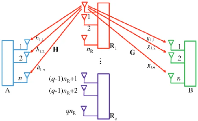
We consider a system with two users, A and B, with n anten-nas, and q relays, R1, R2, . . . , Rq, each of which is equipped
with nRantennas as shown in Fig. 1. For general expressions, we index antennas of the relays from the first antenna of the first relay to the last antenna of the last relay. For example, antennas
(j−1)nR+1, (j−1)nR+2, . . . , j nR denotes the antennas of the j -th relay for all j∈ {1, . . . ,q}. As each relay has nR antennas, there are m=qnRantennas of the relays in total.
A and B want to generate a secret key and are regarded as legitimate nodes. The relays help A and B by amplify-and-forward relaying but they are untrusted. It means that the relays always follow all transmission schemes of the system without an active attack but they are also curious about the confidential information of A and B.
We consider different levels of cooperation among the relays: fully, partially, and non-colluding modes. In the fully colluding mode, all relays cooperate, and they freely exchange the infor-mation including their estimated secret key such as they are inter-connected. In the partially colluding mode, relays form groups, and only the relays in the same group cooperate with
Fig. 1. The system model shown in the first time slot of the first phase of the proposed scheme when the first antenna of the first relay broadcasts a pilot signal to A and B.
each other. For example, in the presence of multiple networks, the legitimate nodes can get help from relays in different net-works, and the relays in each network cooperate with each other. In the non-colluding mode, all relays do not cooperate.1
There is no reliable direct channel between A and B [21]. All channels from A and B to the relays are independent and assumed to remain in the same state in a period of t time slots, i.e., coherence time, and change after every period. At the beginning of a scheme, none of the users and relays knows about the channel status. To reflect both semi-static Rayleigh fading and distance-based path-loss in the channel model, we assume that the channel between antenna i of A
and antenna j of the relays is defined as hj,i = f d−
l
2 hj,i where
f is a circularly-symmetric complex normal random variable
with zero mean and unit variance, i.e., f ∼CN(0,1), dj,i is
the distance between the considered transmitter and receiver, and l is the path-loss exponent. The corresponding channel from antenna i of B and antenna j of the relays is
simi-larly defined as gj,i = f d−
l
2
gj,i. The variances of the channels between antenna i of A and B and antenna j of the relays are
δ2
hj,i =d −l hj,i andδ
2
gj,i =d −l
gj,i, respectively. All nodes know the distances among the nodes, such that they know the variances of all channel coefficients and the noise power at the relays. The channel matrices from A and B to the relays are denoted as H= {hj,i} ∈Cm×n and G= {gj,i} ∈Cm×n, respectively.
We assume that the simultaneous transmissions in a certain time slot are perfectly synchronized and all transmissions are conducted in a 1–Hz bandwidth.
We assume that the transmit power of A, B and the relays when they transmit a pilot signal are denoted by pA, pB, and
pR, respectively. All training symbols used in the schemes are public and known by every station. On the other hand, with the information on the noise power at relays, the relays can compute the mean power of the received signals. Using the information of the received power, the relays amplify the received signal and forward to A and B with the amplification factor which is determined to make the mean transmit power of the relays become pR.
Noise powers at A, B, and the relay are denoted asσA2,σB2 andσR2, respectively. We denote the transpose, conjugate, and conjugate transpose operations of a matrix by (.)T, (.)∗, and
(.)H, respectively. The random variable corresponding to a
sig-nal symbol is written with the same character but capitalized. We denote a row vector with m elements of 1, a diagonal matrix with the diagonal entries taken from vector v, and the m×m
identity matrix as 1m, diag(v), and Im, respectively. We also
denote C(x)=log2(1+x), x+=max(x,0), and the entropy of random variable X and the mutual information of two ran-dom variables X and Y as H(X)and I(X;Y), respectively. Table I summarizes the notations used in this paper.
B. Secret Key Capacity
We consider that two legitimate nodes A, B and an eaves-dropper E observe n realizations X =(X1,X2, . . . ,Xn), Y =
(Y1,Y2, . . . ,Yn), and Z =(Z1,Z2, . . . ,Zn), respectively. A
and B compute a common key denoted as KAand KB, respec-tively, from their observations X and Y . Hence, rK(X;YZ)is an achievable SKR if for every >0 and sufficient large n, if there exists a scheme such that the following requirements are satisfied [14], [22], [23]
Pr{KA=KB} ≤, (1)
1
nI(KA;Z)≤, (2)
1
nH(KA)≥rK(X;YZ)−, (3)
1
n log|K| ≤
1
nH(KA)+ (4)
where Kis the key’s alphabet and|K|is the cardinality ofK and KB, KB∈K.
Obtaining a closed-form expression of the secret key capacity is still an open problem. However, the SKR rK(X;YZ)can be upper and lower bounded as [22]–[24]
rK(X;YZ)≤min[I(X;Y),I(X;Y|Z)],
rK(X;YZ)≥max[I(X;Y)−I(X;Z),
I(Y;X)−I(Y;Z)] (5)
where
I(X;Y|Z)=H(X,Z)+H(Y,Z)−H(Z)−H(X,Y,Z).
(6)
III. KEYGENERATION WITHFULLYCOLLUDINGRELAYS
In this section, we assume that the relays are fully cooperat-ing and the coherence time is long enough to support the key generation scheme, which will be proposed in this section. It means that the channels remain the same until the scheme is completely performed.2
2We will discuss the case that the coherence time is shorter than the required time for the scheme in Section V.
TABLE I
NOTATIONS USED THROUGHOUT THE PAPER
A. Proposed Transmission Scheme
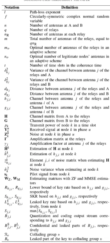
Fig. 2. In the first time slot of Phase 2, the first antenna of A and the first antenna of B simultaneously transmit a pilot signal. There are n time slots in this phase.
• Phase 1: In each time slot, each relays’ antenna transmits a pilot signal sR= √pRto A and B during m time slots as shown in Fig. 1. The pilot signals transmitted from all antennas of the relays during m time slots can be written in matrix as √pRIm where column i is the pilot signal
transmitted in time slot i . The received signal at A and B in Phase 1, respectively, are given by
Y1A=
√
pRHTIm+Z1A=
√
pRHT +Z1A, (7)
Y1B=
√
pRGTIm+Z1B=
√
pRGT +Z1B (8)
where element(i,j)in matrices Yuk and Zuk, k= {A,B}, are the received signal and noise at antenna i of node k in time slot j of phase u, respectively. These subscripts are also used in phases 2 and 3 as follows with the same meaning.
• Phase 2: In time slot i of this phase,∀i ≤n, both antennas i of A and B simultaneously and respectively
trans-mit sA= √pA and sB= √pB as shown in Fig. 2. The received signal at the relays in all n time slots of Phase 2 can be written as
Y2R=√pAHIn+√pBGIn+Z2R
=√pAH+√pBG+Z2R. (9)
• Phase 3: In time slot i of this phase,∀i ≤n, all antennas
of the relays amplify their corresponding received signals in time slot i of Phase 2 and simultaneously forward it to A and B as shown in Fig. 3. The technique here is sim-ilar to analog network coding [25]–[27]. The difference among different time slots in this phase is that the data they forward are from different pairs of antennas of A and B in Phase 2. The received signals at A and B in Phase 3, respectively, are given by
Y3A=HTY2R+Z3A
=√pAHTH+√pBHTG+HTZ2R+Z3A, (10)
Y3B=GTY2R+Z3B
=√pAGTH+√pBGTG+GTZ2R+Z3B (11)
where =diag([γ1, γ2, . . . , γm]), γj =
pR pAδ2
h j+pBδg j2 +σR2
is the amplification factor at antenna
Fig. 3. In time slot i of Phase 3, all antennas of the relays amplify-and-forward their corresponding received signal in time slot i of Phase 2.
j of the relays, andδ2hj andδ2gj are the variances of the channel between A and B, respectively, and antenna
j of the relays. The amplification factor is determined
based on the variance of the received signal [28], [29], i.e., the signal received in the corresponding time slot in Phase 2, and this amplification factor guarantees the mean transmit power of the relay to be pR. The expected values of the channels depend only on the distances between the corresponding transmitter and receiver pairs. For simplicity of analysis, we assume all antennas of a legitimate node are approximately located at the same location so the amplification factors at each antenna of a relay in different time slots are the same and the received signal at A or B can be written in form of a matrix product of a diagonal matrix and Y2R.
B. Key Generation from Channel Estimation
In this subsection, we present how to generate a key after the proposed transmission in previous subsection performed. A and B estimate and quantize all channels between them and the relays. If channel hj,i is quantized to bit stream Bj,i, the key
generated based on all channels in matrix H is given by
1≤j≤m
1≤i≤n
Bj,i (12)
where is the concatenation of all bit streams in the argu-ments of it. Since there are n antennas at A and B and total m antennas at the relays, the number of channels that can be used to generate the secret key is nm. For channel estimation, we consider the ZF and the MMSE schemes [30], [31], which are generally used in current systems, and their performance on key generation will be compared in Section VI.
1) Zero Forcing: From (7), we can estimate H at A, ˆHA, using ZF scheme, as
ˆ
HA=
Y1AT √
pR =
H+ZˆA (13)
where ˆZA=
Z1AT
• Estimating G at B, ˆGB, from (7) as
ˆ
GB=
Y1BT √
pR =
G+ZˆB (14)
where ˆZB=
Z1BT
√pR .
• Cancelling the self-interference signal, √pBGTG of
Y3B, in (11) by using ˆGBin (14), and obtaining ˜Y3 B, given by
˜
Y3B=Y3B−√pB(GˆB)T(GˆB)
=√pAGTH+GTZ2R+Z3B
−√pBZˆBTG−
√
pBGTZˆB−√pBZˆTBZˆB. (15)
• Estimating H at B, ˆHB, from ˜Y3Bas
ˆ
HB=WZY˜3B (16)
where subscript Z refers to ZF, and the estimating matrix
WZ using ˆGB is given in (17) (shown at the bottom of the page). In order to make the estimation reliable, it is necessary to have the number of rows of ˜Y3Bnot smaller than the number of rows of ˆHB, i.e., n≥m.
2) MMSE: The channels from an antenna at A (or B) to
all antennas of the relays are independent from the channels from another antenna at A (or B) to all antennas of the relays. Therefore, for MMSE estimation, we split Y2R in (9) and ˜Y3B
in (15) into columns y2R
i and ˜y
3
Bi, respectively. Note that y
2
Ri is
the received signal vector at all antennas of the relays in time slot i of Phase 2 and ˜y3B
i is the received signal vector at all B’s antennas in time slot i of Phase 3. Here, ˜y3Bi depends on y2R
i
but not on y2R
i, i
=i , so it depends on n channels between the
i -th antenna of A and all antennas of the relays. Hence, we can
WZ=
√
pA
ˆ
GBT H√pA
ˆ
GBT
−1√
pA
ˆ
GBT H =
−1
√ pA
ˆ
GB∗GˆBT
−1
ˆ
GB∗ (17)
RE
˜y3B i
˜y3B i
H
=pAGTAG∗+σR2GT2G∗+σB2In+
σ2 B
pR
GT2G∗Ui +
σ2 B
pR
UiGT2G∗+tr
GUiGH
σ2 B
pR
In
+ pBσB2
pR
GT2G∗+σ
4 BpB
pR2 tr(
2)(I
n+Ui)
=pAGTAG∗+σR2G
T2
G∗+σB2In+
σ2 B
pR
GT2G∗Ui+
σ2 B
pR
UiGT2G∗
+
m
j=1
γj|gj,i|2σ
2 B
pR
In+
pBσB2
pR
GT2G∗+σ
4 BpB
p2R tr(
2)(I
n+Ui) (19)
I
ˆ
HAj,i;HˆBj,i ≥C ⎛ ⎜ ⎜
⎝ E
|hj,i|2
E|ˆzAh j,i|
2+E|ˆzB
hj,i| 2+E
|ˆzA
h j,i|
2E|ˆzB
h j,i|
2
E[|hj,i|2]
⎞ ⎟ ⎟
⎠=C
⎛ ⎜ ⎝ δ 2 h j ˆ σ2 A+σˆB2+
ˆ
σ2 AσˆB2 δ2
h j
⎞ ⎟
⎠Rhj,i. (25)
estimate these n channels based on n elements of vector ˜y3Bi, which is given by
˜y3B i =
√
pAGTHsi+GTz2Ri +z3Bi −
√
pBZˆTBGsi
−√pBGTZˆBsi −√pBZˆTBZˆBsi (18)
where si =[0 0 . . .1 . . . 0 0]T with 1 at row i therefore Hsiis
column i of H. In the following, we calculate the corresponding variance matrices, given in (19) (shown at the bottom of the page). where Ui is a q×q matrix with element(i,i)of 1 and
other elements of 0,
A=diag
δ2
h1, δ
2
h2, . . . , δ
2
hm
, (20)
and
CE
˜y3B i(Hsi)
H=E
GTHUiHH
=pAGTA.
(21)
Using R in (19) and C in (21), the estimating matrix of MMSE can be obtained as WM=R−1CH where subscript M refers to MMSE. Since B does not have the exact information about G and, ˆGBand ˆhave been used. Hence, column i of H, i≤n,
can be estimated at B as
ˆhB
i =WM˜y3Bi. (22)
On the other hand, considering entry hj,i, from (13), the
estimated of hj,i at A is given by
ˆ
hAj,i =hj,i+ˆzAhj,i (23)
where ˆzAh j,i =
ˆ
ZAj,i = Z1
A j,i
√pR. Since the exact expression of the estimated of hj,i at B is complicated, we write it in the form of
ˆ
where ˆzBh
j,i is the estimation error. We use simulation rather than the closed form to show the mutual information between the estimated channel at A and the estimated channel at B. In the simulation, the estimation error can be calculated as ˆzBh
j,i = ˆ
hBj,i −hj,i.
C. Achievable Secret Key Rate
1) Secret key rate based on hj,i and gj,i: The key
gener-ated at A (or B) is the concatenation of keys genergener-ated from each estimated channel ˆhAj,iand ˆgAj,i(or ˆhBj,iand ˆgBj,i). Denoting
ˆ
σ2 AhE
|ˆzAh
j,i|
2 and ˆσ2 BhE
|ˆzBh
j,i|
2, we present a lower
bound of I
ˆ
HAj,i;HˆBj,i as (25) (shown at the bottom of the
previous page) [10]. The inequality in (25) is because ˆzBh j,i is neither independent from hj,i nor Gaussian. Hence, Rhj,i is a lower bound of the key rate achieved at A and B based on hj,i.
In the following, we present the leaked key rate. In time slot
i of Phase 2, relay j receives signals from the i -th antennas of
A and B simultaneously. Similarly to (9), we can present the received signal at relay j in time slot i of Phase 2 as
yR2j,i =
√
pAhj,i+√pBgj,i+z2Rj,i (26)
where yRj2,i and z2Rj,i are entries in row j and column i of matri-ces Y2R and Z2R, respectively. Since the antennas of A and B transmit one by one in Phase 2, the information about hj,i and gj,i only appears in yRj2,i, i.e., the received signal at relay j in
time slot i of Phase 2, but not at other antennas of the relays nor in other time slots. Therefore, relay j can only estimate hj,i
and gj,i from yRj2,i. The maximum information that relay j can
know about ˆhAj,iis given by [32]
I
YR2j,i;HˆjA,i =log2
wRwAH
|WA
R H|
(27)
where
wR=E
yRj2,i
yRj2,i ∗
= pAδ2h j+pBδ2g j+σR2, (28)
wA
H =E
ˆ
hAj,i
ˆ
hAj,i ∗
=δ2
h j+σˆ
2
Ah, (29)
WAR H =E
yR2
j,i ˆ
hAj,i y
2 Rj,i
∗ ˆ
hAj,i ∗
. (30)
From (27), we have
I
YR2j,i;HˆjA,i
=log2
δ2
h j +σˆ
2 Ah
pAδh j2 +pBδ2g j+σR2
δ2
h j+σˆAh2
pAδ2h j+pBδg j2 +σR2 −pAδh j4
(31)
=C
⎛
⎝ pAδh j4
δ2
h j +σˆAh2
pAδh j2 +pBδg j2 +σR2 −pAδ4h j
⎞ ⎠
LAhj,i. (32) The maximum information that relay j can know about ˆgBj,i
when knowing ˆhAj,iis given in (33) (shown at the bottom of the page) [10]. From (25), (32), and (33), we obtain
I
ˆ
HAj,i;HˆBj,i −I
YR2
j,i;Hˆ A
j,i (34)
+I
ˆ
GAj,i;GˆBj,i −I
YRj2,i,GˆBj,i|HˆAj,i (35)
≥Rhj,i −L
A
hj,i +
+Rgj,i −L
B
gj,i +
Sj,i (36)
where Rhj,i, L A
hj,i, and L B
gj,i are given in (25), (32), and (33), respectively, and Rgj,i is defined similarly to Rhj,i in (25).
2) Total secret rate: Based on the designed transmission
scheme, all signals that A, B and the relays observe are
{Y1A,Y3A},{Y1B,Y3B}, and Y2R, respectively. Therefore, the lower bound of the maximum achievable SKR SU between A and B can be written in (37) (shown at the bottom of the page)
LBgj,i I
YR2j,i;Gˆ
B
j,i|HˆAj,i =I
PAHj,i+
PBGj,i +ZR2j,i,Hj,i+
ZA j1 ,i √
PR
;Gj,i+
ZB j1 ,i √
PR
=I
Gj,i +
ZRj2,i √
PB
− Z
1 A j,i
√ PR
PA
PB;
Gj,i+ ZB j1 ,i √ PR =C ⎛ ⎜ ⎜ ⎝ δ2 gj σ2 R pB +
σ2 ApA pRpB+
σ2 B pR +
σ2 R pB +
σ2 ApA pRpB
σ2 B pRδ2 g j ⎞ ⎟ ⎟ ⎠ (33)
SU=rK
Y1A,Y3A;Y1B,Y3BY2R
≥rK
ˆ
H1A,1, . . . ,HˆmA,n,gˆA1,1, . . . ,GˆAm,n;Hˆ1B,1, . . . ,HˆmB,n,GˆB1,1, . . . ,GˆBm,nY2R (37)
=
n
i=1
rK
ˆ
where function rK(X;YZ)was described in subsection II-B. The inequality in (37) is due to the loss of information when processing. The equation in (38) (shown at the bottom of the previous page) is because the received signal at relays in time slot i of Phase 2 and the received signal in time slot i of Phase 3 are independent from those in other slots of the corresponding phase. Let us denote
ˆ
HAi =
ˆ
H1A,i, . . . ,HˆmA,i ,GˆAi =
ˆ
GA1,i, . . . ,GˆAm,i ,
ˆ
HBi =Hˆ1B,i, . . . ,HˆmB,i,GˆBi =GˆB1,i, . . . ,GˆBm,i. (39)
From (38), we can obtain the inequality in (40)–(45) (shown at the bottom of the page) where Sj,i is given in (34) and SL
is the lower bound of the total SKR of our proposed scheme. Equations (40) and (41) are obtained by applying the chain rule of mutual information. Inequality (42) is obtained because all rates rK(.)in (41) are not negative. Inequality (43) is obtained by applying the lower bound of a SKR given in (5). The first equation in (45) is due to the fact that for a certain value of
i , ˆHjA,i, 1≤ j ≤m, are pairwise independent and so are ˆGAj,i. In Section VI, we will use the lower bound of SL to show the
benefits of the proposed scheme in simulation results.
IV. KEYGENERATION WITHNON-ANDPARTIALLY
COLLUDINGRELAYS
In Section III, we considered the case that all relays are col-luding. If the relays are not colluding or only some of them are colluding, we can increase the SKR. This can be achieved because each of colluding group may get less information about the channels leading to a reduced leaked key rate. After esti-mating ˆhAj1,i
1, A quantizes and encodes it into bit stream Bj1,i1
in such a way that Bj1,i1can be separated to two streams BSj1,i1
and BLj1,i
1where B
L
j1,i1is leaked to the corresponding relay with
SU≥
n
i=1
rK
ˆ
HAi ,GˆAi ;HˆBiGˆiBy2Ri =
n
i=1
rK
ˆ
HAi ;HˆBi,GˆiBy2Ri +rK
ˆ
GAi ,HˆBi ,GˆiB|HˆAi y2Ri (40)
=
n
i=1
rK
ˆ
HAi ;HˆBi y2Ri +rK
ˆ
HAi ;GˆBi|HˆBi y2Ri +rK
ˆ
GAi ;GˆBi |HˆAi y2Ri +rK
ˆ
GAi ;HˆiB|HˆAi GˆBi y2Ri (41)
≥
n
i=1
rK
ˆ
HAi ;HˆBi y2Ri +rK
ˆ
GiA;GˆBi|HˆAi y2Ri (42)
≥
n
i=1 max
I
ˆ
HAi ;HˆBi −I
y2Ri;HˆAi ,I
ˆ
HAi ;HˆBi −I
y2Ri;HˆBi
+
n
i=1 max
I
ˆ
GAi ;GˆBi −I
y2Ri;Gˆ
A
i |HˆAi ,I
ˆ
GAi ;GˆBi −I
y2Ri;Gˆ
B
i|HˆAi (43)
≥
n
i=1
I
ˆ
HAi ;HˆBi −I
y2Ri;Hˆ
A
i +I
ˆ
GAi ;GˆBi −I
y2Ri;Gˆ
B
i |HˆiA (44)
=
n
i=1
m
j=1
I
ˆ
HAj,i;HˆBj,i −I
YR2j,i;Hˆ
A
j,i +I
ˆ
GAj,i;GˆBj,i −I
YR2j,i;Gˆ
B
j,i|HˆAj,i = n
i=1
m
j=1
Sj,i SL (45) antenna j1 while BSj1,i1 is confidential3. This can be done by designing the coding scheme such that BSj1,i1 bits are at higher levels than BLj1,i
1 bits, as in [33]. It means that one needs to
know BLj
1,i1correctly to decode B
S
j1,i1, but it does not guarantees
one can decode BSj1,i
1 correctly.
Let us consider channel hj2,i2 such that antennas j1 and j2
of the relays belong to different relays which are not collud-ing with each other while i1and i2are not necessarily different. Here we can also split the corresponding output bit stream Bj2,i2
into two streams BSj2,i
2and B
L
j2,i2. Assuming
BLj1,i
1
=BLj2,i 2
where |x| is the number of bits of bit stream x, the secret bit stream Bj1,i1;j2,i2 corresponding to hj1,i1 and hj2,i2 can be
designed as
Bj1,i1;j2,i2 =B
S
j1,i1∪B
S
j2,i2∪
BLj1,i1 ⊕B
L
j2,i2 (46)
where∪and⊕refer to bit stream concatenation and bit-wise XOR operation, respectively. Since each of the two correspond-ing relays know only one of BLj1,i1 and BLj2,i2, both of them cannot derive BLj1,i1 ⊕BLj2,i2. Certainly, both BSj1,i1 and BSj2,i2 are confidential to these relays, therefore Bj1,i1;j2,i2is
confiden-tial. By using (46), we can increase the SKR which contributed by hj1,i1 and hj2,i2 an amount ofBLj1,i1⊕B
L
j2,i2
compared to the case with fully colluding relays.
In the following, we consider the case that BLj1,i1and BLj2,i2do not have the same length. Without loss of generality, we assume thatBLj1,i
1
>BLj2,i 2
. We then split BLj1,i
1into B
L,1
j1,i1and B
L,2
j1,i1
3For example, the non-secret key can be generated with rate Rh
Fig. 4. To arrange the bit streams leaked to different colluding groups, they are optimally paired in a parallel way.
such thatBL,1j1,i 1
=BLj2,i 2
. Here, BL,2j
1,i1should be dropped and Bj1,i1;j2,i2 becomes
Bj1,i1;j2,i2 =B
S
j1,i1∪B
S
j2,i2∪
BL,1j1,i1⊕BLj2,i
2 . (47)
If we keep BL,2j1,i1 and design as
Bj1,i1;j2,i2 =BSj1,i1∪B
S
j2,i2∪
BL,1j1,i
1 ⊕B
L
j2,i2 ∪B
L,2
j1,i1,
(48)
Bj1,i1;j2,i2 becomes not confidential because the relay with
antenna j1can know BL,2j1,i
1.
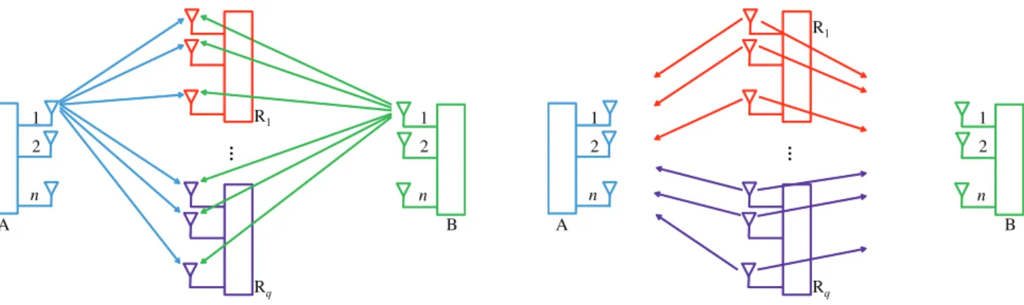
To maximize the SKR in the non-colluding relay case, we need to pair two antennas of non-colluding relays such that their leaked bit streams, say BLj1,i1and BLj2,i2, have the least dif-ference in length. Depending on how the relays are colluding, A and B have more or less options for selecting antenna pairs of the relays. In fact, even when all relays are non-colluding, antennas of a relay can be seen as “colluding” with each other. Therefore, we optimize the paring based on the antennas of the relays and regard it as a partially colluding case. All antennas of each relay are treated as in a colluding group. The optimization problem is then to arrange all antennas of the relays in pairs such that any two antennas of the same colluding group are not arranged in a pair.
For this, we assume that there are r colluding antenna groups denoted by Rv, v= {1,2, . . . ,r}. As described above, the
relays with antennas in groupRv can get a leaked part of the
key given by
Bv
j∈Rv
1≤i≤n
BLj,i. (49)
We can arrange the leaked bit streams into two parallel streams as shown in Fig. 4 which shows an example of two parallel streams of leaked bits when r=5. Here BSrepresents the bit streams that can be used for the superposition, and BA repre-sents the ones that should be abandoned. Here the bit streams should be arranged such that|BS|is maximized.
For the case with non-colluding and single-antenna relays, one simple solution is pairing antennas j and j+1, j =
{1,3,5, . . . ,}, i.e., XORing BLj,i and BLj+1,i, i = {1,2, . . . ,n}
together. In this case, the lower bound of the final SKR is given by
S≥ n
i=1
q
j={1,3,5,...}
Rhj,i −L A
hj,i +
+Rgj,i −L
B
gj,i +
+min
LAhj,i +L B
gj,i,L A
hj+1,i +L B
gj+1,i . (50)
V. ADAPTIVEKEYGENERATIONSCHEME WITHRELAY
ANDANTENNASELECTION
The previous section presents the proposed scheme when the coherence time is long enough to utilize all channels for key generation. During the three phases of the proposed transmis-sion scheme, the total number of required time slots to perform the proposed scheme is m+2n, i.e., m, n, and n time slots are required in Phase 1, 2, and 3 respectively. In practice, the coher-ence time t is not always equal or longer than this duration. If
t <m+2n, we cannot utilize all relays and legitimate nodes’ antennas, and have to choose the number of antennas partici-pating in the key generation such that the highest SKR can be achieved. Denote mand n as the number of antennas of the relays and the number of antennas at a legitimate node partic-ipating in the scheme, respectively. Denote cm and cn as two
certain ways (in the set of all ways Cm andCn, respectively)
of selecting mout of m antennas of the relays and nantennas out of n antennas of A and B, respectively. Denoting cx as the
way (in the set of all waysCx) to pair antennas of the relays so
that the leaked streams to them are XORed together in the non-/partially colluding modes, we have the optimization problem as
max
m={1,...,m},n={1,...,n}cm∈Cmaxm,cn∈Cn max
cx∈Cx
SL(m,n,cm,cn)
(51)
subject to m≤n m+2n≤t.
In (51), SL(m,n,cm,cn)is the rate given in (45) when m, n, cmand cnare parameterized.
The function SL(m,n,cm,cn)depends on I
ˆ
HAj,i;HˆjB,i in
(25) where σB2=E
|ˆzBh
j,i|
2 in IHˆA
j,i;Hˆ
B
j,i is not given in
a closed form because ˆzBh
j,i is given by a complicated expres-sion with high power exponent of matrices. Moreover, since the optimization are non-convex and difficult to solve, we use exhaustive search (ES) to find the optimal solution for (51). The result will be discussed in Section VI. We consider both optimal and sub-optimal solutions as follows.
A. Optimal Solution
In this subsection, we consider two optimal solutions with and without channel status information (CSI)
1) Exhaustive Search without CSI (ES-NCSI): This scheme
is used when we have to select the relays and antennas at A and B before the scheme starts. As we do not know the status of any channel at this time, we have to select relays and antennas based on the expected values of channels and noise. The optimization problem becomes
max
m={1,...,m},n={1,...,n}cmmax∈Cm max
cx∈Cx
SL(m,n,cm) (52)
subject to m≤n m+2n≤t.
A and B because those antennas have the same channel vari-ances. We pair the relays’ antennas as cx. Then, we calculate
the expected SKR based on realizations of channels and noise. We save the SKR corresponding for the selection. After that, we choose a different set of mantennas of the relays. When all sets are considered, we select other values of mand nwhich sat-isfies the constraints in (52). At the end, we compare all cases and select the case with the highest lower bound of SL.
2) Exhaustive Search with CSI (ES-CSI): After Phase 1, A
and B can estimate the channels between them and the relays so they can base on this information to select the most suitable antennas to participate in Phase 2. Note that this scheme can be used as an additional scheme after the ES-NCSI scheme is used, and we now need to find cn∈Cn that maximizes SL. Here, SL(cn)is the rate given in (45) when cnis parameterized. Since
the objective function is given by a complicated expression with high power exponent of matrices, similarly to the NCSI mode, we use exhaustive search to find the optimal cn.
B. Sub-optimal Solution (SO)
In this subsection, we propose sub-optimal solutions for the relay and antenna selection in the adaptive key genera-tion scheme. We propose that the problem of (51) is divided into two independent problems: 1) the problem aims to deter-mine the maximum allowable number of estimated channels, and 2) the problem aims to select the most suitable channels based on the known information about the channels for a given maximum allowable number channels obtained in the first prob-lem. These steps includes selecting antennas of the relays in the selection without CSI in subsection V-A1 and selecting the legitimate antennas in selection with CSI in subsection V-A2. More details of the proposed scheme are presented in following subsections.
1) Maximizing the number of estimated channels: If we
select m antennas of the relays to transmit pilot signals in Phase 1, we need m time slots. The rest of time slots t−m will be
used for Phases 2 and 3. These two phases requires the same number of time slots, so each of them will bet−2mtime slots long wherexis the greatest integer which is not greater than
x. Consequently, in Phase 2,t−2mpairs of antennas transmit, where a pair here refers to an antenna of A and an antenna of B. The total number of estimated channel pairs is thusω(m)= mt−2m. Since the key rate can be enhanced asω(m)increases, we need to obtain the optimal mothat maximizesω(m). This
can be readily obtained as
mo=
⎧ ⎪ ⎪ ⎨ ⎪ ⎪ ⎩
t
2 for t mod 4=0,
t+1
2 for t mod 4=1,
t+2
2 for t mod 4=2,
t−1
2 for t mod 4=3.
(53)
2) Selecting the most suitable channels: Different from the
problem above, the optimization problem for selecting the most suitable channels is difficult to solve because as seen in (25) and (32), the SKR is a complicated function of channel variances. Hence, we propose sub-optimal solutions. Let us examine two following steps:
• Selecting the most suitable antennas of the relays: among m antennas of the relays, we need to select mo. Hence,
there are mmo
cases to be considered in the selection. Denoting cRas the case to be considered and CR as the set of allmmo
cases, we write the optimal case as
cRo=arg max
cR∈CRHE,G[SL(cR)]. (54)
On the other hand, as a sub-optimal solution, we can also choose the moantennas with the greatest minimum
channel variance toward A and B such as
{m1, . . . ,mmo} =arg max
j
$
min
δ2
hj, δ 2
gj
%
. (55)
The antenna with higherδ2h j andδ
2
gj gives a higher key rate but also gives a higher leaked key rate. However, these selection proposes a simpler method to select anten-nas while providing a fairly good key rate. In the simula-tion results, this method is referred to as sub-sub-optimal with NCSI (SSO–NCSI).
• Selecting the most suitable legitimate antennas: After mo
antennas of the relays are selected, Phase 1 of the pro-posed scheme can be carried out. These antennas of the relays, one by one, transmit a pilot signal. After this phase, A can estimate the status of all channels between it and the relays. Now we need to select no= t−2mo
anten-nas at A, which transmit a pilot signal in Phase 2. There are totally nno
cases for this selection. Different from the first step, in the second step, the exhaustive search to select the optimal antennas can be done based on the cur-rent status of the estimated channels at A rather than the channel variances. However, A does not know the current status of the channels from B to the relays, it has to rely on variance information for those channels. This selection process can be done similarly at B as well. In fact, the selections at A and B are performed independently and based on different information. WhenCAandCBare the sets of all possible antenna combinationsnn
o
at A and B we can obtain the optimal selection as
cAo=arg max cA∈CAEG
[SL(cA)], (56)
cBo =arg max
cB∈CBEH[SL(cB)]. (57)
On the other hand, as a sub-optimal solution, we pro-pose to select noantennas at A and noantennas at B with
maximum sum of channel gains as
{nA1, . . . ,nAno} =arg max
j
|hˆA
j,i|2, (58)
{nB1, . . . ,nBno} =arg max
j
|gˆBj,i|2. (59)
This solution is obtained due to the fact that the antenna with higher δh2
j and δ 2
gj gives a higher key rate but also gives a higher leaked key rate. Moreover, the antennas with the greatest
&
these selection proposes a simpler method to select anten-nas. In the simulation results, this method is referred to as sub-sub-optimal with CSI (SSO–CSI).
Considering all the cases of the scheme, we can see that if we solve the optimization regarding the required time of the scheme and the optimization regarding the colluding mode sep-arately, we have the steps as follows. First, we can select the number of antennas of the relays and legitimate nodes’ antennas to participate in the scheme satisfying the constraint regarding the coherence time. Second, the most suitable antennas at the relays and the legitimates nodes are selected. Third, if the relays are not fully colluding, the bit streams, corresponding to relays, are selected and XORed together when generating the secret key. We can see that the two optimization problems mentioned above are not independent because the antennas, selected to have the highest SKR, are not necessarily to be the most suitable antennas when we consider the XORing the leaked bit streams. However, separating the two problems into steps as presented can be treated as a sub-optimal solution.
VI. SIMULATIONRESULTS
In this section, we use Monte Carlo simulation to show the performance of our proposed scheme. We consider the case when A and B are respectively located at (0, 0)m and (2, 0)m in the Cartesian coordinate system. We run iterations in each of which q relays are uniformly and randomly distributed in a square with an edge of 2 and center at (1, 0). The channels are given in the form of f d−2l as introduced in Section II and
path loss exponent is l=3. Since we do not have a closed form of Rhj,i in (26), we first obtain the expected values of channel estimation errorsE
|ˆzhB
j,i|
2by averaging the error over all
iter-ations of random fading channels and noise for the determined realization of relays’ locations. We then obtain the final results by averaging the lower bound of the secret key rate, obtained fromE
|ˆzhB
j,i|
2, over all iterations of relays’ locations. In the
following, we consider several cases with different simulation settings which will be described accordingly.
In the first case, we assume that the coherence time t is
long enough to support the considered network. Moreover, to
distinguish different cases of colluding modes of the relays, we consider that there are 4 relays each of which is equipped with one antenna. The number of antennas at a legitimate node should be at least 4, so we select n=5. In this case, the coher-ence time t should be at least 14 channel uses. We consider three cases of colluding modes: fully colluding mode, partially colluding mode and non-colluding mode. In the partially col-luding case, we consider that R1and R2are cooperating and R3 and R4are cooperating.
Moreover, we also consider the secret key generation scheme proposed in [15] which is regarded here as a benchmark scheme, denoted as BM in figures. In fact, it is designed for non-fully colluding relays, so we can compare with the pro-posed scheme in partially and non-colluding modes. In this scheme, first, each node broadcasts a pilot so that other nodes can estimate the channels between that node and them. Second, a relay broadcasts a signal achieved by XORing two values of
Fig. 5. Secret key rate with varied SNR when there are 4 relays in three different colluding modes.
the channels from A and B so that A (B) can compute the chan-nels between that relay and B (A). Third, another relay performs the same procedure. Knowing all the channels in the network, A and B will XOR the two values of the channels between A and the two relays, and use it as a secret key. Since each relay only knows the channels linked to it, no relay can compute the key.
Fig. 5 shows the SKR of the proposed scheme in three col-luding modes and two estimation methods, and that of the benchmark scheme in two colluding modes. As expected, in any mode, the MMSE estimation achieves a higher SKR than ZF estimation does. Besides, in the three colluding modes, the non-colluding mode provides the highest SKR while the fully colluding mode provides the lowest SKR. This is obvious since in the fully colluding mode, we cannot pair the relays and XOR their leaked bit streams, BLj,i, at all. In the meantime, the dif-ference in SKRs of the non-colluding and partially colluding modes is quite small and does not change with SNR because the partially colluding mode only provides more options to pair the relays than the non-colluding mode does.
Compared to the proposed scheme, the estimated channels in the benchmark scheme suffer a smaller error because the relays estimate the channels and broadcast the XORed of the esti-mations while in the proposed scheme, the relays amplify and forward the signals. However, the benchmark scheme requires many more time slots therefore provides a much lower SKR.
On the other hand, in Fig. 5, we also show the result of the approximating amplification factor (AAF) scheme for the case that A and B do not know the noise power at the relays. This can happen when the relays are not honest to correctly report the noise power to A and B. In this case, A and B approxi-mate the amplification factors by using channel variances and transmit powers only. Instead of usingγj =
pR pAδ2
h j+pBδ2g j+σR2
,
A and B use ˜γj =
pR pAδ2
h j+pBδ2g j
as the amplification factor at
Fig. 6. Secret key rate when the coherence time is limited at 3 channel uses.
In the second case, we assume that the coherence time is short and equal to 3 channel uses. The proposed scheme there-fore can only support one relay and one antenna at each node even though there may be several available relays and antennas at the nodes. In this case, we need to select the most suit-able relays and antennas. We also consider sub-sub-optimal adaptive modes with no relay selection (SSO-NRS), no CSI (SSO-NCSI), and CSI (SSO-CSI). In the NRS mode, one relay and one antenna at A and B are randomly selected and the scheme is performed. In the NCSI mode, first, for each relay, the channel with smaller magnitude in the two channels from A and B to that relay is selected and regarded as “worse” channel. Second, the relay with the “worse” channel with the great-est magnitude is selected. After that, the antennas at A and B are randomly selected. In the CSI mode, besides the relay is selected as above, the antenna of A or B with the channel with the greatest magnitude to the relay is selected.
Assuming there are qm relays and nm antennas at A and B,
we exam two cases of qm =nm =2 and qm =nm =10 in each
adaptive mode. As seen in Fig. 6, a scheme with more antennas and more candidates to select results in a higher performance. With no relay selection, the number of antennas does not affect. In the three different sub-optimal schemes modes, the SSO-CSI has not only the highest performance but also the biggest increase with the number of relays/antennas.
In the third case, we consider the performance of the scheme for different values of coherence time. We consider the case that there are 20 available single-antenna relays and 20 anten-nas at A and B. The relays are fully colluding and follows the NCSI mode. Corresponding to a certain value of coherence time t, the optimal number of relays and antennas at A and B are calculated. The lower part of Fig. 7 shows the optimal number of antennas of the relays (mo) and the optimal number
of legitimate nodes’ antennas (no) with respect to the
coher-ence time. The upper part of of Fig. 7 shows the corresponding non-modified SKR.
From Fig. 7, we can see that for the SO scheme with closed-form closed-formulas for mo and no, increasing the coherence time
may decrease the SKR at a few points while for the ES scheme, the SKR never decreases. For instance, the SKR of the SO
Fig. 7. Secret key rate with varied coherence time when SNR=20 dB.
Fig. 8. Different relay and antenna selection schemes and the benchmark scheme with non-colluding relays and ES–CSI with fully colluding relays in limited coherence time.
scheme decreases from t=8 to t =10 channel uses. This is because sometimes the increase in the coherence time is not enough to increase no but increase mo. In this case, more
antennas make the relays more powerful in getting leaked infor-mation rather than helping the legitimate nodes. Consequently, the greatest m and n satisfying the constraints are not neces-sarily the optimal values. This depends on balance between
exploiting the help and avoiding the maliciousness from the
untrusted relays.
Fig. 9. Different relay and antenna selection schemes with fully colluding relays, the benchmark scheme and ES–CSI with non–colluding relays in limited coherence time.
Fig. 10. Secret key rate with varied number of antennas at A and B when SNR=20 dB and there are 2 relays each of which is equipped with 2 antennas.
When we move from a more optimal to a less optimal scheme or from the CSI to the NCSI selection, the rate decreases by a small value because the scheme with a more optimal selection or the CSI mode, with a higher complexity level, consider more candidates to choose than their corresponding counterparts.
In the fifth case, we explore the effect of legitimate nodes’ antennas on the performance of the scheme. Fig. 10 shows the SKR and leaked key rate when the number of used antennas at A and B, n, is varied. When there are 2 relays each with 2 anten-nas, SNR=20dB and MMSE estimation is used. As expected, increasing n always increases the SKR and the leaked key rate as shown in Fig. 10. This is because the number of estimated channels used for key generation increases faster than the num-ber of time slots. In case of fully colluding relays, the leaked key rate is higher than the SKR because the relays can get a large portion of information of hj,i and gj,i from the received
signals in Phase 2. However, in case of non-colluding relays, A and B can exploit the leaked information by XORing them together leading to a high SKR compared to a low leaked key rate as shown.
Fig. 11. Secret key rate with varied number of antennas at each relay when SNR=20 dB.
In the sixth case, we consider the effect of the number of the antennas of the relays on the performance of the scheme. The upper part of Fig. 11 shows the length of the secret key and the leaked key. The key length here is defined as the number of bits of the key without being normalized by the number of time slots used. The lower part of Fig. 11 shows the corresponding SKR and leaked key rate. In this scenario, we consider 2 relays and 12 antennas at A and B. Note that 12 antennas at A and B are used because even in the case with the most antennas at the relays, the constraint n≤m is still satisfied. Different from the
effect of the legitimate nodes’ antennas on the key rate shown in Fig. 10, the SKR increases with nRuntil nR=4 and decreases after that as shown in the lower part of Fig. 11.
VII. CONCLUSION
We proposed a novel scheme for generating a secret key between two multi-antenna legitimate nodes with the help of multiple untrusted relays, equipped with multiple antennas. The proposed key generation scheme was designed to achieve high-est secret key rate (SKR) for non-, partially, and fully colluding modes of relays and to adapt to different values of channel coherence time. Through the simulation results, we verified that a secret key can be generated with untrusted relays even for fully and partially colluding cases, and the proposed scheme achieves higher SKR than a prior work. By presenting the exis-tence of the optimal number of untrusted relays, we also verified that exploiting more antennas of untrusted relays cannot always be helpful in achieving a higher SKR. The outcomes of our work provide insights on the efficient secret key generation with untrusted relays for various scenarios, and open several issues for future research including the effect of interference on SKR and the group key generation with untrusted relays.
REFERENCES