A Plastic Design Method for RC Moment Frame Buildings against Progressive
Collapse
Hadi Faghihmaleki
Molla-Sadra College of Ramsar, Technical and Vocational University, Ramsar, Iran e-mail: [email protected]
Abstract
In this study, progressive collapse potential of generic 3-, 8- and 12-storey RC moment frame buildings designed based on IBC-2006 code was investigated by performing non-linear static and dynamic analyses. It was observed that the model structures had high potential for progressive collapse when the second floor column was suddenly removed. Then, the size of beams required to satisfy the failure criteria for progressive collapse was obtained by using the virtual work method; i.e., using the equilibrium of the external work done by gravity load due to loss of a column and the internal work done by plastic rotation of beams. According to the nonlinear dynamic analysis results, the model structures designed only for normal load turned out to have strong potential for progressive collapse whereas the structures designed by plastic design concept for progressive collapse satisfied the failure criterion recommended by the GSA code.
Abstrak
Metode Desain Plastis untuk RC Rangka Pemikul Momen Bangunan terhadap Keruntuhan Progresif. Dalam penelitian ini, potensi keruntuhan progresif data bangkitan 3-, 8- dan 12-lantai bangunan rangka beton bertulang pemikul momen dirancang berdasarkan IBC-2006 diselidiki dengan melakukan analisis statis dan dinamis non-linear. Diamati bahwa struktur model memiliki potensi besar untuk runtuh secara progresif saat kolom lantai dua tiba-tiba dihilangkan. Kemudian, ukuran balok yang dibutuhkan untuk memenuhi kriteria kegagalan untuk keruntuhan progresif diperoleh dengan nmenggunakan metode kerja virtual; yaitu, menggunakan keseimbangan kerja eksternal yang disebabkan oleh beban gravitasi akibat hilangnya kolom dan kerja internal yang disebabkan oleh rotasi plastis balok. Berdasarkan hasil analisis dinamik nonlinear, struktur model yang hanya dirancang untuk beban normal menghasilkan potensi yang kuat untuk runtuh secara progresif, sedangkan struktur yang dirancang dengan konsep desain plastis untuk keruntuhan progresif memenuhi kriteria kegagalan yang direkomendasikan oleh kode GSA.
Keywords: RC moment frame buildings, progressive collapse, plastic design, virtual work method, non-linear dynamic analysis
1.
Introduction
The progressive collapse refers to the phenomenon that local damage of structural elements caused by abnormal loads results in comprehensive damage of the structure. An abnormal load includes any loading condition that is not considered in normal design process but may cause significant damage to structures. The potential abnormal loads that can trigger progressive collapse are categorized as: aircraft impact, design/construction error, fire, gas explosions, accidental overload, hazardous materials, vehicular collision, bomb explosions, etc. [1-3]. To prevent the progressive collapse caused by abnormal loads, the National Building Code of Canada [4] specified requirements for design of major elements,
establishment of connection elements, and ways of providing load transfer paths. The Eurocode1 [5] presented a design standard for selecting plan types for preventing progressive collapse, and recommended that buildings should be integrated. In the United States, specific provisions related to the progressive collapse are not yet provided in design codes such as the International Building Code (ICC) [6]; however the American Concrete Institute (ACI-318) [7] requires structural integrity (for example, continuity insurance of reinforcing bars,) so that partial damage by abnormal load does not result in comprehensive damage.
for alternate load path method are linear static, linear dynamic, nonlinear static, and nonlinear dynamic methods, which were also recommended for seismic analysis and design for structures in the FEMA 273 [11]. In linear analysis, modeling is simple and analysis is convenient compared to the nonlinear analysis. Studies and researches about progressive collapse mostly evaluate the collapse mechanism of structures caused by man-made hazards. Current progressive collapse analysis procedures, which take into account only the gravity loads, may not have the capabilities to simulate the progressive collapse of structures due to earthquakes. On the other hand, natural hazards such as earthquakes can generate significant lateral loads and stress reversals which can overload structural elements and result in the loss of load carrying elements and trigger disproportionate collapse of the structures. So analysis of structures with removed columns during the earthquakes must be regarded.
Sasani and Sagiroglu [12], evaluated progressive collapse resistance of an actual six-story reinforced concrete frame structure following simultaneous removal of two adjacent exterior columns and then changes in columns axial forces and load redistribution were discussed.
Lu et al. [13] simulated the extreme nonlinear behavior of reinforced concrete structural elements with the fiber-beam-element model and multi-layer-shell-element model. They used simple reinforced concrete frames and reinforced concrete frame-shear wall structures to benchmark the capacity of the numerical model and then investigated the progressive collapse mechanism of the actual buildings.
Kim and Park [14] evaluated the progressive collapse potential of three and nine-story special moment resisting frames by nonlinear static and dynamic analysis. They demonstrated that the model structures which are designed only for normal loads have high progressive collapse potential whereas the structures
story buildings. The proposed method identifies the ductility demand and supply to determine progressive collapse potential under column removal. They concluded that besides the tying force requirements, ductility demand and supply must be considered in the support joints of the failed members to provide structural strength.
Yi et al. [17] studied the progressive collapse failure of a reinforced concrete frame due to the loss of a column by static experiment and they investigated the redistribution and transition of the load resisting mechanism based on the experimental results.
The objective of this study is to check the applicability of the plastic design (Based on the virtual work method) to estimate the size of girders required to prevent progressive collapse of a RC moment resisting frame designed with IBC-2006 design code. The plastic design is a procedure to find out the required plastic moment capacity of members to prevent formation of collapse mechanism of structures when they are subjected to seismic load. In this study, the same concept was applied in the progressive collapse which occurs as a result of formation of plastic hinges and collapse mechanism, and its applicability for progressive collapse was evaluated.
2.
Methods
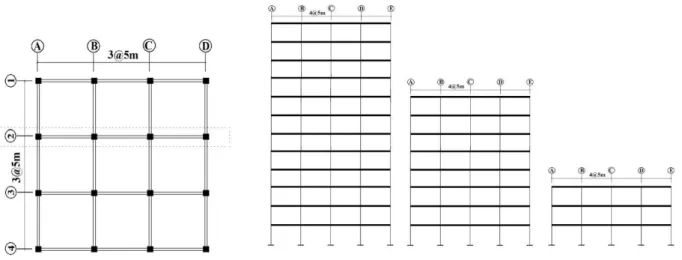
Modelling. In this section, the detailed information for example structures and analysis methods for progressive collapse are provided. To apply the plastic design procedure, RC moment resisting frames were designed based on IBC-2006 design code. The example structures 3-, 8- and 12-storey structures. Figure (1) shows the structural plan and the frames of interest.
The frame (2) was separated and analyzed for progressive collapse. The design dead and live loads are
2 5
Cm Kg
and 2 3
Cm Kg
Figure 1. Analysis Model Structures: a) Plan; b) Frames (No. 2)
The design seismic load was determined based on the IBC-2006 with the seismic coefficients SDS and SDL equal to 0.62 and 0.18, respectively. The R factor corresponding to RC moment frame building, which is 8, is applied to obtain design base shear. Table (1) shows the member size of the analysis model structures. The point load imposed on a column is from the internal beam connected to the column. The load was suddenly applied for seven seconds on the model structures with a second story column removed as shown in Figure (2) to activate vertical vibration. The beams are considered to be failed when their rotations exceed the limit state of 0.035 radian as specified in the FEMA-356 guidelines, which is larger than the 0.02 radian recommended by the FEMA-356 [18] to satisfy the collapse prevention design objective for seismic load.
In this study, the performance of structures subjected to sudden removal of a column is investigated by nonlinear dynamic analysis using the SeismoStruct software [19]. Mazzoni et al. [20] and Faroughi and Lee [21] performed non-linear static analyses in both horizontal and vertical directions to observe load-displacement relationship and plastic hinge formation of model structures. The columns and girders were modelled using the Nonlinear Beam-Column element with five integration points. The bi-linear material model with the post-yield stiffness of 2% of the initial stiffness was used (the damping ratio was assumed to be 5% of the critical damping). Dynamic analysis was carried out using the Newmark time integration method and the Newton-Raphson solution algorithm. Time step of 0.02 second was used for time-history analysis.
Progressive collapse potential of code-designed struc-tures. To evaluate the progressive collapse potential of the model structures, which were designed based on conventional designed code without considering prog-ressive collapse, nonlinear dynamic analyses were carried
Figure 2. Configuration of Vertical Load Applied on a Model Structure
Table 1. Member Size of the Analysis Model Structures
Story Columns (cm)
Beams
(cm) Story
Columns (cm)
Beams (cm)
1 65 × 65 65 × 65 7 40 × 40 40 × 40
2 65 × 65 65 × 65 8 40 × 40 40 × 40
3 65 × 65 65 × 65 9 40 × 40 40 × 40
4 50 × 50 50 × 50 10 35 × 35 35 × 35
5 50 × 50 50 × 50 11 35 × 35 35 × 35
6 50 × 50 50 × 50 12 35 × 35 35 × 35
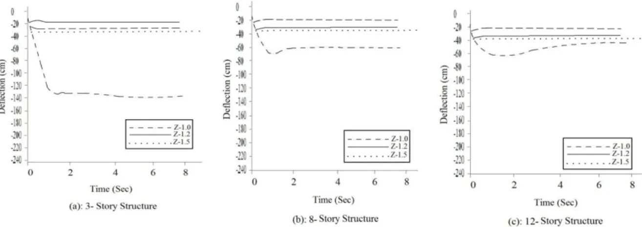
out without a column with a gravity load suddenly applied on them (Figure 2). Figure (3) shows the time history of vertical deflection, where the limit state specified in the GSA guidelines is plotted as horizontal dotted line.
Figure 3. Time History of Vertical Deflection at the Lost Column-beam Connection of Model Structures with Various Beam Plastic Moment of Inertias: a) 3-storey Structure; b) 8-storey Structure; c) 12-storey Structure
be carried out. It can be seen that the vertical deflection increases as the bay width increases and the girder size decreases. Figure 3 shows that the vertical deflection in the 3-story structure decreased more than the limit state when the plastic section moduli of beams were increased by 20%. The section moduli of the 8-storey structure should increase by 50% to reduce the maximum deflections less than the given limit state. It can also be seen that the vertical deflection of 12-storey structure is smaller than that of the 3-storey structure with the same bay width because the girder sizes were increased due to larger seismic load and more structural members participated in resisting progressive collapse. The increase in beam size to enhance the resistance to progressive collapse may lead to strong beam-weak column combination and result in formation of weak story when the structure is subjected to earthquake load. The formation of weak story can be identified by large inter-story drift or formation of column plastic hinges. According to the AISC Seismic Provision for concrete buildings [22, 23 and 24], the weak story can be prevented if a structure is designed in such a way that the summation of plastic moment capacity of columns is larger than that of beams.
0 . 1 > ∑ ∑
pb M
pc M
(1)
−
∑
=
∑
g A
uc P yc c
pc Z F
M (2)
(
y yb b uv)
pb R F Z M
M =∑ +
∑ 1.1 (3)
In the above Equations (1-3), Mpc and Mpb are the plastic
moment capacity of columns and beams, respectively; Zc and Zb are the plastic section modulus of columns
and beams, respectively; fyc and fyb are the yield strengths of columns and beams, respectively;
p
uc is the required axial strength of columns; Aɡ is the cross-sectional area of columns; Ry is the ratio of the expected to nominal yield strength; and Muv is the additional moment caused by shear force. It can be seen that the strong column-weak beam condition of Equation (1) is not satisfied in every story of the model structure. The same phenomenon was also observed in the other model structures when the girder size was increased by the same proportion. Therefore, whenever girder size is increased to prevent progressive collapse, it would be necessary to increase the column size in accordance with Equation (1) to prevent unfavorable failure mode when the structure is subjected to seismic load.3.
Results and Discussion
Determination of beam plastic moment. Progressive collapse occurs due to formation of collapse mechanism in all girders located in the bays in which a column is removed. The formation of local collapse mechanism may not lead to total collapse (comprehensive damage) if catenary action is fully activated in girders. However, the activation of catenary action fully depends on connection details and cannot be guaranteed in all concrete structures. Moreover, the effect of catenary action is not considered in the limit states for concrete structure given in the current GSA guidelines.
equilibrium of the internal and the external works triggered by sudden removal of a column.
The external work is done by the gravity load imposed on the removed column and the vertical deflection. The internal work is computed by the plastic moments of the beams, which are initially unknown, multiplied by the rotation of the beams. The unknown beam plastic moment required to stabilize the structure can be obtained by equating the internal and the external works.
Figure (4) shows the deformed configuration of a beam for a 3-storey structure with an internal column removed. The loss of a column results in the vertical deflection δ and the beam rotation θ in the structure with identical span length. After the column is removed progressive collapse will not occur if the external work done by gravity load is in equilibrium with the internal work done by plastic rotation of beams at the vertical deflection less than the limit state. Equation (4) shows the equilibrium of the external and internal works, from which the unknown plastic moment demand of the i th beam (Mpi) can be obtained using the vertical load
p
acting on the removed column and the actual vertical deflection δ and the beam rotation θ1 [25, 26 and 27].i pi N
i M
P.δ =
∑
=1 .θ (4)Where N is the number of plastic hinges. In this case, all bays have the same length and the same size of beams are used in all stories. The deflection δ can be expressed in terms of the rotation
θ
multiplied by the span length L and the required beam plastic moment Mp is obtained as follows:N Pl
Mp = (5)
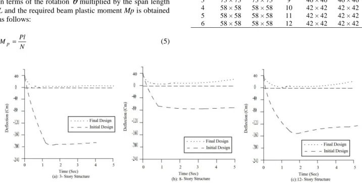
Performance of re-designed structures. 3-, 8- and 12-storey structures were designed using the plastic design procedure, and the member sizes of the re-designed structures are presented in Table (2). The column size is also increased proportional to the beam size to meet the strong column-weak beam requirement.
Figure (5) shows the time history of the vertical deflection triggered by sudden loss of a second story column. The secondary stiffness ratio and the damping ratio were assumed to be 2% of the initial stiffness and 5% of the critical damping, respectively.
Figure 4. Beam Rotation Angles and Joint Deflection Caused by Loss of a Column
Table 2. Member Size of Model Structures Designed by Virtual Work Method
Story Columns (cm)
Beams
(cm) Story
Columns (cm)
Beams (cm)
1 73 × 73 73 × 73 7 46 × 46 46 × 46
2 73 × 73 73 × 73 8 46 × 46 46 × 46
3 73 × 73 73 × 73 9 46 × 46 46 × 46
4 58 × 58 58 × 58 10 42 × 42 42 × 42
5 58 × 58 58 × 58 11 42 × 42 42 × 42
6 58 × 58 58 × 58 12 42 × 42 42 × 42
for design of RC moment frame structures to prevent progressive collapse. The plastic moment of beams required to stabilize a structure subjected to sudden loss of a column was computed from the equilibrium condition of the external work done by gravity load and the internal work done by plastic rotation of beams. Moreover, this comparison showed that the increase of only the girder size for the purpose of preventing progressive collapse may result in weak story (when the structure is subjected to seismic load). The formation of weak story can be prevented by increasing the column size in such a way that the strong column-weak beam requirement is satisfied. The nonlinear dynamic analyses results showed that the structures designed without considering progressive collapse did not satisfy the failure criterion required by the GSA guidelines; on the other hand, the structures redesigned by plastic design method to prevent progressive collapse turned out to satisfy the given failure criterion in most of the model structures. However, it should be mentioned that, as the catenary action, which arises after the flexural resistance of a beam is lost, is not considered in this study, the analysis and design results may be conservative.
References
[1] M. Li, M. Sasani, J. Eng. Struct. 95 (2015) 71. [2] G.R. Abdollahzadeh, H. Faghihmaleki, H. Esmaili,
Alexandria, Eng. J. (2017). http://dx.doi.org/10. 1016/j.aej. 2016.09.015.
[3] G.R. Abdollahzadeh, H. Faghihmaleki, Int. J. Dam. Mech. 0 (2017) 1. doi: 10.1177/1056789516651919. [4] N.B.C.C, National Research Council of Canada,
Ottawa, Canada, 1995.
[5] Eurocode 1, Actions on structures, European Committee for Standardization, Brussels, 2002. [6] I.C.C. International Building Code, International
Code Council, Falls Church, Virginia, 2006.
[11]FEMA NEHRP Guidelines for the Seismic Rehabilitation of Buildings, FEMA-273, Federal Emergency Management Agency, Washington, D.C, 1997.
[12]M. Sasani, S. Sagiroglu, J. Struct. Eng. 134 (2008) 478.
[13]X. Lu, X. Lin, Y. Ma, Y. Li, L. Ye, the 14th World Conf. Earth. Eng. Beijing, China, 2008, p.12. [14]J. Kim, J. Park, J. St. Comp. Struct. 8 (2008) 85. [15]F. Fu, J. Construc. St. Research. 65 (2009) 1269. [16]A.G. Vlassis, B.A. Izzuddin, A.Y. Elghazouli, D.A.
Nethercot, J. Eng. Struct. 30 (2008) 1424.
[17]W. Yi, Q. He, Y. Xiao, S.K. Kunnath, ACI. Struct. J. 105 (2008) 4.
[18]FEMA, Prestandard and Commentary for the Seismic Rehabilitation of Buildings, FEMA-356, Federal Emergency Management Agency, Washington, D.C., 2006.
[19]SeismoSoft, A Computer Program for Static and Dynamic Nonlinear Analysis of Framed Structures, SeismoStruct, Version 6, http://www.seismosoft. com/, 2012.
[20]S. Mazzoni, F. McKenna, M.H. Scott, G.L. Fenves, Pac. Earth. Eng. Res. Cent. Berkeley, California, 2006.
[21]S. Faroughia, J. Lee, J. Buil. Eng. 2 (2015) 1. [22]AISC Seismic Provisions for Structural Steel
Buildings, American Institute of Steel Construction, Chicago, Illinois, 2005.
[23]H. Faghihmaleki, E.K. Najafi, A.H. Aini, Int. J. Struc. Integ. 8 (2017) 24.
[24]A. Khaloo, S. Nozhati, H. Masoomi, H. Faghihmaleki, J. Build. Eng. 7 (2016) 23.
[25]S.S.J. Moy, Plastic Methods for Steel and Concrete Structures, New Jersey, USA: Wiley, 1981, p.221. [26]G.R. Abdollahzadeh, H. Faghihmaleki, Int. J.
Earth. Struc. 12 (2017) 47.