Analyzation of Multistoried Building Strengthening in Seismic Region
within fills and Using Etabs
Kunche Bhavana
1*,P.M.Lavanya
2M.Tech(Student)
1,
Assistant professor
2in Dept.of Civil engineering
kakinada institute of engineering & technology-II,korangi
ABSTRACT
Current building codes for seismic design and evaluation in Europe and American component execution based criteria that involve the estimation of inelastic reaction of the building because of seismic. These seismic requests can be precisely decide by utilizing strategies for nonlinear time history analysis. Streamlined strategies in view of nonlinear static analysis, known as sucker analysis technique and straight element analysis, known as time history analysis strategy, have been produced by a few controls to fulfill the execution based criteria for seismic design and evaluation of buildings. This proposal manages multistory buildings with open (soft story) ground floor are inalienably defenseless against crumple because of seismic burdens, their developments is still boundless in create countries. Social and utilitarian need to give auto parking spot at ground level far exceeds the notice against such buildings from designing group. In this review, 3D expository model of multistory building have been producing for multistoried building model and breaking down utilizing auxiliary analysis instrument 'ETABS'. The investigative model of building incorporates immeasurably vital segments that impact the mass, quality, solidness of the structure. Numerical outcomes for the accompanying seismic requests considering the inelastic conduct of the building, malleability coefficients of structures.
Keywords: soft story, ground soft, infill, mass, quality,
solidness, inelastic conduct, float proportion, flexibility coefficients.
I. Introduction
The limit of auxiliary individuals to experience inelastic disfigurements represents the basic conduct and damageability of multi-story buildings amid seismic tremor ground movements. Starting here of view, the evaluation and design of buildings ought to be founded on the inelastic disfigurements requested by quakes, other than the anxieties instigated by the identical static strengths as determined in a few seismic directions and codes. In spite of the fact that, the present practice for seismic tremor safe design is predominantly represented by the limit of auxiliary individuals to experience inelastic distortions administers the basic conduct and damageability of multi-story buildings amid quake ground movements. Starting here of view, the evaluation and design of buildings ought to be founded on the inelastic disfigurements requested by tremors, other than the burdens incited by the comparable static strengths as determined in a few seismic controls and codes. Standards of drive based seismic design, there have been huge endeavors to consolidate the ideas of distortion based seismic design and evaluation into the quake building hone. As a rule, the investigation of the inelastic seismic reactions of buildings is not just helpful to enhance the rules and code arrangements for minimizing the potential harm of buildings, additionally imperative to give sparing design by making utilization of the saved quality of the building as it encounters inelastic disfigurements. In late seismic rules and codes in Europe and USA, the inelastic reactions of the building are resolved utilizing nonlinear static strategies for analysis known as the weakling techniques. Execution Based Engineering (PBE) in relationship with existing ideas of seismic tremor safe design requires
nonlinear analysis to acquire appraisals of
levels of seismic execution for a building for determined levels of tremor ground movement are indicated. The execution is checked as far as post versatile disfigurements. ATC-40 gives the Capacity Spectrum Method for actualizing PBE for buildings. It utilizes Nonlinear Static Pushover (NSP) analysis to build up the limit bend (a plot of base shear Vs rooftop uprooting). In this paper, speculative multistoried buildings (i.e., twelve storied and nine storied with infill and with ground soft story) situated in zone V of medium soil locales has been broke down and designed for load mixes given in code and assessed utilizing weakling analysis.
II. Literature Survey
A venture on study for SESIMIC EVALUATION OF MULTISTORIED BUILDING WITH GROUND SOFT STORY& WITH INFILLS these review I have taken around 2 unique models of the buildings are contemplated. The open first story is a critical utilitarian prerequisite of all the urban multi-story buildings, and henceforth, can't be disposed of. Elective measures should be received for this particular circumstance. The dirt adaptability should be inspected deliberately before settling the investigative model of a building. Trial examination of RC casings with block stone work infill dividers having focal opening subjected to cyclic relocation stacking was done with a target to look at the execution of infill workmanship outlines with that of uncovered edges subjected to turn around cyclic removal controlled stacking. They reasoned that the normal starting solidness of an infill RC edge is around 4.3times than that of an exposed casing where the brick work is unreinforced, and around 4.0 circumstances that of uncovered edge when the stone work is strengthened. From quality perspective it demonstrates that the unreinforced stone work infill outlines had around 70% more prominent quality than exposed edges; the esteem was around half higher on account of RC infill outlines. Furthermore presumed that the yield relocation of in filled edges is much littler than that of the uncovered casing, and consequently demonstrated that the infill outlines have extensively more noteworthy pliability. Hence, dynamic weakling bends for the buildings are produced as the best fit bends for the dynamic outcomes. For every building, the base shear limit is assessed by contrasting the static and element weakling bends. At that point, the sucker bends together with a regular design reaction range are used to decide the
distortion state at which the seismic requests are assessed for execution evaluation of buildings. Numerical outcomes for the accompanying seismic requests are demonstrated considering the inelastic conduct of the buildings: rooftop floats, story add up to floats, bury story float proportions, malleability coefficients and plastic pivot dispersions. The outcomes show that the seismic requests assessed by applying the sucker methods concur well with the aftereffects of the nonlinear time-history examinations for the multistory steel and RC buildings in this review. In this manner, these seismic requests are worthy for ordinary design purposes. When all is said in done, the execution level of the lower stories in light of the entomb story float proportions is better for the steel buildings contrasted with the RC buildings, though the upper stories of the RC buildings experience bring down bury story floats.
The plastic pivot disseminations indicate the
significance of consolidating the impacts of inelastic disfigurements, which create in the building amid the weakling analysis, through the horizontal load designs.
III. Soft or flexible story
The least more adaptable part, in the way of compel transmission, at first story may make a basic circumstance amid a tremor; the firmness intermittence between the first and the second stories may bring about noteworthy basic harm, or even the aggregate crumple of the building. A standout amongst the most widely recognized cases of delicate story can be seen on the alleged "Open floor" in the primary story of present day
private structures. The basic components are
homogenously dispersed all through the building, however the flats are situated on the upper floors with numerous workmanship dividers, while the least floor is left absolutely or halfway free of segments for stopping vehicles and for social ranges that require wide spaces. On account of twofold stature first delicate stories, sections are exceptionally adaptable not just because of the aggregate or incomplete nonappearance of dividers however therefore of their altogether more noteworthy tallness in connection with those from the upper floors. This setup is one of the trademark models of current outline for office structures, lodgings and clinics, in which the entrance for overall population has an awesome significance. . This design is likewise extremely basic in blended utilize structures, in which the urban code requires that the lower floors are of a more noteworthy stature keeping in mind the end goal to suit shops with mezzanines for capacity. As a variation of this arrangement, we can discover the utilization of segments of various statures in a side of the working to give more significance to that space. Fig. 2.4 shows two cases of present day structures with twofold tallness first delicate story arrangement. In a large portion of the seismic tremors that happen in contemporary urban areas, there are dependably instances of given way delicate first story. Fig. 2.5 presents two cases of late extreme harm because of delicate first story of inconsistency in L'Aquila seismic tremor, Italy in 2009, and in the private complex "San Fernando" of minimal
effort lodging in Lorca, Spain in 2011, where toward the starting the structures didn't indicate obvious serious harm, however, every one of the structures of this mind boggling that had delicate first story, were pulled down. The secured walkway, or arcade, is a setup got from delicate story inconsistency. It is a colonnade, similar to an order, in the principal story of the front façade that is normal for structures on business roads. It is a typical variety of abnormality in the dispersion of the resistance, solidness and mass of structures, which is likewise incorporated into UZR of contemporary urban communities as a legacy of the medieval city.
Another adaptation of the secured walkways is the twofold tallness sort. The majority of the UZR incorporate this setup in blended utilize structures (business and private), which permits to have twofold tallness first stories, a mezzanine for capacity and twofold stature grandstand confronting the secured walkway, with a specific end goal to demonstrate the stock. The utilization for this situation of extremely thin sections, and in addition the utilization of twofold stature discharge spaces, makes an unpredictable circulation of the responsive mass, resistance and firmness.
Soft story failures
IV. Seismic analysis procedures
Seismic analysis is a subset of structural analysis and is the calculation of the response of a building structure to earthquakes .A building has the potential to wave back and forth during an earthquake .This is called the fundamental modes and it is the lowest frequency of building response. Most of the buildings however have higher modes of response, which are uniquely activated during earth quakes.
Safety Evaluation of Reinforced Concrete Buildings
Safety against collapse of reinforced concrete is usually defined in terms of its ductility ratios. The design of reinforced concrete structures is performed by using resistance smaller than the one required for the system to remain elastic under intense ground shaking. Then, the seismic codes implicitly cause structural damages during strong earthquake motions and the design relies on the capacity of the structures to undergo large inelastic deformations and to dissipate energy without collapse. This design methodology is used by all design standards including IS 1893.
SEISMIC VULNERABILITY
The vulnerability of a building subjected to an earthquake is dependent on seismic deficiency of that building relative to a required performance objective. The seismic deficiency is defined as a condition that
will prevent a building from meeting the required performance objective. Thus, a building evaluated to provide full occupancy immediately after an event may have significantly more deficiencies than the same building evaluated to prevent collapse.
Depending on the vulnerability assessment, a building can be condemned and demolished, rehabilitated to increase its capacity, or modified so that the seismic demand on the building can be reduced. Thus, structural rehabilitation of a building can be accomplished in a variety of ways, each with specific merits and limitations related to improving seismic deficiencies.
HOW DO BUILDINGS RESIST EARTHQUAKE FORCES?
As a building responds to ground motions produced by an earthquake, the bottom of the structure moves immediately, but the upper portions do not because of their mass and inertia. Figure-3.4 shows the base of a building moving while the upper part lags behind.
Fig -behaviour of building in ground acceleration
Horizontal forces accumulate along the floors and roof and then are distributed through the vertical supports into the foundation. A structural engineer must design a building so that lateral forces are distributed throughout the building without a break. Several structural systems, such as floors, walls, and columns, may be used in new buildings to reduce the effects of earthquakes and associated natural disasters.
Fig –forces acting on the building during ground
excitation
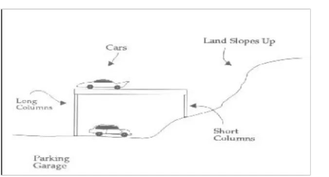
STIFFNESS:
A building is comprised of both unbending and adaptable components. For instance, shafts and segments might be more adaptable than solid dividers or boards. Less inflexible building components have a more prominent ability to assimilate a few cycles of ground movement before disappointment, as opposed to solid components, which may bomb unexpectedly and smash abruptly amid a seismic tremor. Tremor drives consequently concentrate on the stiffer, inflexible components of a building. Thus, structures must be built of parts that have a similar level of adaptability, so that one component does not twist excessively and exchange the vitality of the quake to less pliable When the tremor struck, the more drawn out, more adaptable sections at the front of the building passed the seismic tremor drives on to the short, stiffer segments in the back as opposed to dispersing the powers similarly among the majority of the segments. Diversion, the degree to which a basic component moves or curves under weight, assumed a noteworthy part. The more drawn out sections basically diverted or bowed without splitting. The short segments, in this way, were overpowered and split.
Fig showing long and short columns
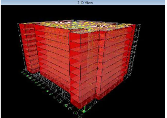
V. Analytical Modelling
Most construction standards endorse the strategy for investigation in light of whether the building is customary or sporadic. All the codes recommend the utilization of static investigation for symmetric and chose class of customary structures. For structures with sporadic designs, the codes propose the utilization of element investigation strategies, for example, reaction range technique or time history examination.
Seismic codes give diverse strategies to do parallel load examination, while doing this investigation infill dividers display in the structure are ordinarily considered as non auxiliary components and their nearness is generally overlooked while investigation and outline. However despite the fact that they are considered as non-auxiliary components, they have a tendency to connect with the edge when the structures are subjected to parallel burdens.
In the present review horizontal load investigation according to the seismic code for the accompanying sort of structures, exposed edge, full infill, base delicate story, focal center divider, shear divider in x and y heading and alongside focal center divider, shear divider in corners and alongside focal center divider is completed and an exertion is made to concentrate the impact of seismic loads on them and in this way evaluate their seismic powerlessness by performing weakling examination. The investigation is done utilizing etabs examination bundle.
DESCRIPTION OF THE SAMPLE BUILDING
The plan layout for all the building models are shown in figures
Model 1: Twelve storied Building with full infill
masonry wall (230 mm thick) in all story’s.
Model 2: Twelve storied Building (ground story) no
walls in the soft storey and full brick infill masonry
walls (230 mm thick) in the upper story’s.
Model 3: Nine storied Building with full infill masonry
wall (230 mm thick) in all story’s
Model 4: Nine storied Building (ground story) no walls
in the first storey and full brick infill masonry walls
(230 mm thick) in the upperstory’s.
Figure: Plan Layout
Figure: Plan Layout
Fig: Elevation of twelve storied Building Model 1 (full infill)
Fig: Elevation of twelve storied Building Model 2 (ground soft)
Fig: Elevation of nine storied Building Model 3 (full infill)
Fig: Elevation of nine storied Building model4 (ground soft)
Natural Periods And Average Response Acceleration Coefficients:
For Twelve-storied Frame Building:
Fundamental Natural period,
longitudinal and transverse direction,
Ta=0.075*360.75=1.102sec
For medium soil sites, Sa/g = 1.36/T=1.36/1.102=1.234
For twelve-storied brick infill’s buildings:
Fundamental natural period longitudinal direction,
Ta=0.09/√25=0.018 sec
For medium soil sites, Sa/g = 1+15T=1.27
Fundamental Natural period, transverse direction,
Ta=0.09/√20=0.0045 sec
For medium soil sites, Sa/g = 1+15T=1.067
Design horizontal seismic coefficient,
Design horizontal seismic coefficient,
g
Sa
x
R
I
x
Z
A
h2
Ah= (0.36/2) x (1.5/5) x 2.060 =0.11124 in longitudinal direction.
Ah= (0.36/2) x (1.5/5) x 2.11 =0.1139 in transverse direction.
Manual calucuation:
Natural Periods And Average Response Acceleration Coefficients:
For nine-storyed Frame Building: Fundamental Natural period, longitudinal and transverse direction,
Ta=0.075*360.75=1.102sec
For medium soil sites, Sa/g = 1.36/T=1.36/1.102=1.234
For nine-storied brick without
infill’s walls in buildings:
Design horizontal seismic coefficient,
g
Sa
x
R
I
x
Z
A
h2
Ah= (0.36/2) x (1.5/5) x 1.234=14.9931
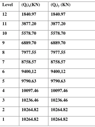
Table (A) : Deign Seismic Based Shear for twelve storied buildings
Table 1: Distribution of Lateral Seismic Shear force
for twelve storied
building for Model 1
Level (Qi)x(KN) (Qi)y(KN)
12 1840.97 1840.97
11 3877.20 3877.20
10 5578.70 5578.70
9 6889.70 6889.70
8 7977.55 7977.55
7 8758.57 8758.57
6 9400,12 9400,12
5 9790.63 9790.63
4 10097.46 10097.46
3 10236.46 10236.46
2 10264.82 10264.82
1 10264.82 10264.82
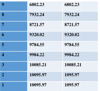
Table 2 : Distribution of Lateral Seismic Shear force for twelve storied building for Model 2
Level (Qi)x(KN) (Qi)y(KN)
12 1820.01 1820.01
11 3855.23 3855.23
9 6802.23 6802.23
8 7932.24 7932.24
7 8721.57 8721.57
6 9320.02 9320.02
5 9784.55 9784.55
4 9984.22 9984.22
3 10085.21 10085.21
2 10095.97 1095.97
1 10095.97 1095.97
Table (B) : Deign Seismic Based Shear for nine storied buildings
Table 3 : Distribution of Lateral Seismic Shear force for nine storied building for Model 3
Table 4 : Distribution of Lateral Seismic Shear force for nine storied building for
Model 4
Level (Qi)x(KN) (Qi)y(KN)
9 1701.86 1701.86
8 3423.52 3423.52
7 4808.75 4808.75
6 5798.21 5798.21
5 6530.40 6530.40
4 6945.98 6945.98
3 7183.45 7183.45
2 7282.39 7282.39
1 7282.39 7282.39
Figure: Shear diagram for twelve storied Model 1 along longitudinal and transverse direction
VI. Results and Discussions
Most of the past studies on different buildings and unsymmetrical buildings have adopted idealized structural systems without considering the effect of masonry infill and concrete shear walls. Although these systems are sufficient to understand the general behavior and dynamic characteristics of unsymmetrical buildings, it would be interesting to know how real buildings will respond to earthquake forces. For this reason hypothetical buildings, located on level ground having similar ground floor plan have been taken as structural systems for the study.
Level (Qi)x(KN) (Qi)y(KN)
9 1721.07 1721.07
8 3523.14 3523.14
7 4879.75 4879.75
6 5892.15 5892.15
5 6621.08 6621.08
4 7107.03 7107.03
3 7350.00 7350.00
2 7451.24 7451.24
In this chapter, the results of the twelve selected buildings are presented and discussed in detail. The results are includes of all different building models and the response results are computed using the response spectrum and pushover analysis. The analysis and design of the different building models is performed by using ETABS analysis package.
The results of natural period of vibration, base shear, lateral displacements and story drifts, ductility, reduction factor & overall performance for the different building models for each of the above analysis are presented and compared. An effort has been made to study the effect of in fills, concrete core wall and vertical irregularities and mass irregularities in seismic analysis.
TABLE 5.1 DISPLACEMENTS OF 12 STOREY INFILL STRUCTURE IN MM.
0 2 4 6 8 1 0 1 2
0 2 4 6 8 1 0 1 2 1 4 1 6
Y A x is T itle
X
A
xi
s
T
itl
e
B C
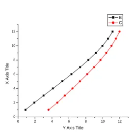
Fig displacement of linear static analysis
of 12thstorey buildings in x–direction.
0 2 4 6 8 10 12
0 2 4 6 8 10 12 14 16 18
Y Axis Title
X
A
x
is
T
it
le
B C
Fig displacement of linear static analysis of 12thstorey
buildings in y–direction.
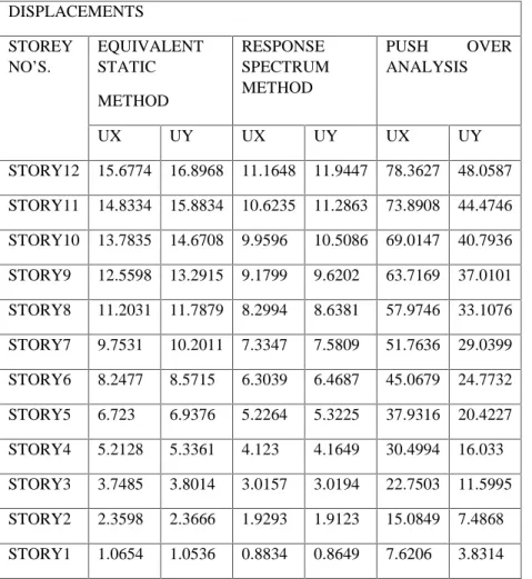
DISPLACEMENTS
STOREY
NO’S.
EQUIVALENT STATIC
METHOD
RESPONSE SPECTRUM METHOD
PUSH OVER
ANALYSIS
UX UY UX UY UX UY
STORY12 15.6774 16.8968 11.1648 11.9447 78.3627 48.0587
STORY11 14.8334 15.8834 10.6235 11.2863 73.8908 44.4746
STORY10 13.7835 14.6708 9.9596 10.5086 69.0147 40.7936
STORY9 12.5598 13.2915 9.1799 9.6202 63.7169 37.0101
STORY8 11.2031 11.7879 8.2994 8.6381 57.9746 33.1076
STORY7 9.7531 10.2011 7.3347 7.5809 51.7636 29.0399
STORY6 8.2477 8.5715 6.3039 6.4687 45.0679 24.7732
STORY5 6.723 6.9376 5.2264 5.3225 37.9316 20.4227
STORY4 5.2128 5.3361 4.123 4.1649 30.4994 16.033
STORY3 3.7485 3.8014 3.0157 3.0194 22.7503 11.5995
STORY2 2.3598 2.3666 1.9293 1.9123 15.0849 7.4868
0 2 4 6 8 10 12
0 2 4 6 8 10 12
Y Axis Title
X
A
x
is
T
it
le
B C
Fig displacement of linear dynamic analysis of
12thstorey buildings in x–direction.
0 2 4 6 8 10 12
0 2 4 6 8 10 12 14
Y Axis Title
X
A
x
is
T
it
le
B C
Fig 5.4 displacement of linear dynamic analysis of
12thstorey buildings in y–direction.
Performance point
The performance point of the building models in longitudinal and transverse directions are shown in figure 5.25 to 5.32 as obtained from ETABS. The values of seismic coefficients Ca and Cv for zone-V are taken from the table 5.11.
Seismic Coefficient, CA
Soil Zone II (0.10)
Zone III (0.16)
Zone IV (0.24)
Zone V (0.36)
Type I 0.12 0.19 0.28 0.37
Type II 0.15 0.23 0.31 0.41
Type III 0.23 0.31 0.35 0.36
Seismic Coefficient, CV
Type I 0.17 0.26 0.37 0.52
Type II 0.23 0.34 0.46 0.60
Type III 0.34 0.53 0.72 0.91
Table-5.11: Interpolated values of Seismic Coefficient (CA and CV) for the soil type
Fig.Performance point of twelve storied building Model 1 along longitudinal direction
Figure: Performance point of twelve storied building Model 1 along transverse direction
VIII. CONCLUSION
Based on the results obtained from different analysis for the various building models, the following conclusion is drawn.
1. The codal time period and analytical time
2. Underestimation of design base shear in case of bare models as compared to the infill models the design of base shear increases with increases in mass and stiffness of masonry infill wall and vice versa.
3. Infill panel increases the lateral stiffness of the
building, measured in terms of the roof displacement there by reducing displacements in all storey levels compared to bare frame models.
4. As model spectral analysis more suitable for
problems involving in the structural design of new structures ,while pushover analysis is more indicated for assessing the sesmic vulnerability of existing structures.
5. From the analysis it came to know that for
analysing the seismic evolution on the structure through E tabs we have to do both the response spectrum analysis and pushover analysis for a structure as for the push over analysis to capture dynamic effects we should calculate using through response spectrum analysis only, and at this displacement we assess the performance of the structure.
6. It came to know that with masonry infill walls
throughout the structure and having soft storey it may easily vulnerable mainly in seismic regions even we came to know these by the
models As compared to Model 1have a
displacement of 3.75% model 2 have a displacement of 6.64%, As compared to Model 3 have a displacement of 5.42% model 4 have a displacement of 10.16%
7. It is essential to consider the effect of masonry
infill for the seismic evaluation of movement resisting RC frames especially for the prediction of its ultimate state. Infills increase the lateral resistance and initial stiffness of the frames they appear to have a significant effect on the reduction of the global lateral displacement. Infills having no irregularity in
elevation having beneficial effects on
buildings. In infilled frames with irregularities, such as ground soft storey, damage was found to concentrate in the level where the discontinuity occurs.
8. The displacements and inter story drift ratios at
edge of the buildings are compared at different levels of the building deformation. the results are drastically changed, at the level below which there is no infill and above which the infill wall is present(ground soft storey),the storey drift has a value of 12mm it exceeds this value .As it has The graph associated with the building model-2 and model-4 is less stiff and yields at a lower base shear value than that of the other building models.
9. The capacity curve is intersecting the demand
curve of the infill structures which indicates that the performance level of the building is good. The capacity curve and demand curve are intersecting only for infill structures. The performance level of the infill structure is good and whereas the soft story structure is worst
Scope for future study
Further studies can be conducted on high rise buildings (sky-scrapers) by providing more thickness of shear walls. Studies can be conducted by providing shear wall at various other locations and also by providing dual system, which consists of shear wall (or braced frame) and moment resisting frame such that the two systems are designed to resist the total design force in proportion to their lateral stiffness considering the interaction of dual system at all floor levels. The moment resisting frames may be designed to independently resist at least 25% of design seismic base shear. For better ductility beam-column junction study can also be made. And further study an existing building can be considered for evaluation. Where, a preliminary investigation using FEMA-273 can be done before evaluation of the existing building using mathematical modelling with the help of FEA package and further it can be evaluated
using Non-Linear Dynamic Analysis and other
software’s like sap
This investigation can also be done on Sloping RCC buildings constructed on hills in hill stations were land is at high cost and it will also attracts the tourists.
REFERENCES
1. Arlekar, N.J., Jain K.S., and Murthy, C.V.R.“Seismic
Response of RC Frame Buildings with Soft First
Storeys”, Proceedings of the CBRI Golden Jubilee
Conference on Natural Hazards in Urban Habitat, New Delhi, 1997.
2. Krawinkler, H., and Seneviratna, G.D.P.K. (1998): Pros & Cons of Pushover Analysis of Seismic Performance Evaluation.
3. Ashraf Habibullah, Stephen Pyle, “Practical three
-dimensional non-linear static pushover analysis”
Structure Magazsanine, Winter, 1998.
4. MOHAMED NOUR EL-DIN ABD-ALLA
“Application of recent techniques of pushover for
evaluating seismic performance of multistory
buildings”, Faculty of Engineering, Cairo University Giza, Egypt September 2007.
5. KasımArmagan KORKMAZ, Fuat DEM_R and
Mustafa S_VR_ “Earthquake assessment of R/C
structures with masonry infill walls” SuleymanDemirel
University, Civil Engineering Department, Cunur,
Isparta, TURKIYE [email protected].
(Received: 06.08.2007; Accepted: 03.10.2007
6.IS: 1893 (Part-I) 2002 (2002): Criteria for Earthquake Resistant Design of Structures, Part-I General Provisions and Buildings, Fifth Revision, Bureau of Indian Standards, New Delhi
7. Kanitkar, R., and Kanitkar, V.,“Seismic Performance
of Conventional Multi-storey Buildings with Open
Ground Storey for Vehicular Parking”, Indian Concrete