Rexroth IndraMotion MTX
Software Installation
R911314880
Edition 01
Commissioning Manual Electric DrivesAbout this Documentation Software Installation
Rexroth IndraMotion MTX Software Installation Commissioning Manual
DOK-MTX***-SOFTINS*V04-IB01-EN-P
Document Number 120-2500-B321-01/EN
This documentation describes the installation and the updating of NC control Rexroth IndraMotion MTX and the network settings.
Description Release Date
Notes
120-2500-B321-01/EN 02.2006 First issue
2005 Bosch Rexroth AG
Copying this document, giving it to others and the use or communication of the contents thereof without express authority, are forbidden. Offenders are liable for the payment of damages. All rights are reserved in the event of the grant of a patent or the registration of a utility model or design (DIN 34-1).
The specified data is for product description purposes only and may not be deemed to be guaranteed unless expressly confirmed in the contract. All rights are reserved with respect to the content of this documentation and the availability of the product.
Bosch Rexroth AG
Bgm.-Dr.-Nebel-Str. 2 • D-97816 Lohr a. Main
Telephone +49 (0)93 52/40-0 • Tx 68 94 21 • Fax +49 (0)93 52/40-48 85 http://www.boschrexroth.com/
Dept. BRC/ESM6 (EgWi/DiHa)
This document has been printed on chlorine-free bleached paper.
Title
Type of Documentation Document Typecode Internal File Reference Purpose of Documentation Record of Revisions Copyright Validity Published by Note
Software Installation Contents
I
Contents
1
General Information About Setup
1-1
1.1 The Setup Program and this Documentation ... 1-1 1.2 System Requirements ... 1-2 Control Modules CMP 40 and CMP 60 ... 1-2 Industrial PCs ... 1-3 1.3 Before You Start Installing the User Interface ... 1-4 1.4 Using Virus Scanners ... 1-4
2
Carrying Out Setup
2-1
2.1 Administrator Privileges ... 2-1 Access Data... 2-1 Logging in as Administrator ... 2-1 2.2 Initial Installation of Rexroth IndraWorks ... 2-2 CD-ROM ... 2-2 Installing Rexroth IndraWorks ... 2-3 Executing Setup without Control Card CMP 40/CMP 60 (Emulation)... 2-8 2.3 Further Steps Before Commissioning an MTX Control ... 2-9 Firewall Settings ... 2-9 Updating the Network Driver ... 2-10 Firmware Download... 2-11 2.4 Uninstalling Rexroth IndraWorks ... 2-12
3
Data Archival/Backup
3-1
3.1 Archiving the IndraWorks Project ... 3-1 3.2 Archiving of Data that are Not Project-Specific ... 3-1
4
Executing a Software Update of IndraWorks
4-1
4.1 Executing an Update of IndraWorks... 4-1
5
Restoring Data
5-1
5.1 Restoring Data That Are Not Project-Specific ... 5-1 5.2 Restoring the IndraWorks Project... 5-1
6
IP Addresses
6-1
6.1 Overview ... 6-1 6.2 Configuration of Communication Interface ... 6-1 Setting the IP Address of the Network Adapter... 6-2 Setting the IP Address of the CMP60 Plug-In Card ... 6-3
II
Contents Software InstallationBasic PC Device Ethernet Connection ... 6-4
7
Network Settings
7-1
7.1 General Information ... 7-1 7.2 Enabling a CD Drive in a Network ... 7-1 7.3 Connecting to a Network Enabled in the CD-ROM Drive... 7-3 7.4 Access to the CMP 40/CMP 60 from an External PC (Routing)... 7-4 Overview... 7-4 Conditions... 7-4 Entering a Route... 7-4
8
MTX Control
8-1
8.1 Introduction ... 8-1 8.2 Overview ... 8-1 8.3 Main Menu ... 8-4 8.4 Power-up... 8-5 8.5 Startup Mode ... 8-6 8.6 Data Backup ... 8-7 8.7 Archive Function ... 8-10 8.8 Firmware Download... 8-11 8.9 Incorporating File Systems (Mount)... 8-13 Using the Dialog Box ... 8-14 8.10 Operating a USB Stick on the MTX as a Mount Directory... 8-16 Configuration ... 8-16 MTX Boot Parameter... 8-16 NFS Parameter... 8-17 Executing an MTX Soft Reset (SR) ... 8-17 8.11 Ethernet Interface ... 8-18 8.12 Boot Parameters... 8-18 8.13 User Level... 8-19 8.14 Contextual Menu... 8-21 8.15 Call Parameters ... 8-219
Index
9-1
10 Service & Support
10-1
10.1 Helpdesk ... 10-1 10.2 Service-Hotline ... 10-1 10.3 Internet... 10-1 10.4 Vor der Kontaktaufnahme... - Before contacting us... ... 10-1 10.5 Kundenbetreuungsstellen - Sales & Service Facilities ... 10-2
Software Installation General Information About Setup
1-1
1
General Information About Setup
1.1
The Setup Program and this Documentation
The setup program installs the Rexroth IndraMotion MTX user interface. Installing the user interface requires experience in working with PCs and with the operating system. Administrator privileges are required for installation.
Note: Setup may be executed only by an experienced user with knowledge of operating systems and with administrator privileges.
The setup program decompresses and installs the user interface and the associated files from the CD-ROM onto your hard disk.
The user interface cannot be operated without this installation. Furthermore, it is possible to update and uninstall the software.
This documentation informs you about how to install and set up the user interface on your hard disk, how to execute an update and how to remove the user interface.
Note: Read these installation instructions and, if necessary, additional documents before you install the software.
What is installed? Who installs the program?
Setup program
1-2
General Information About Setup Software Installation1.2 System
Requirements
Control Modules CMP 40 and CMP 60
Synopsis
The Rexroth IndraMotion MTX control system is based on the CMP 40 and CMP 60 CNC control modules.
CMP60.jpg
Fig. 1-1: CNC control module CMP 40/60
CNC control modules CMP 40 and CMP 60 are the central units in the MTX control system. They have CNC and PLC functions. They are installed in an unassigned PCI slot, either in industrial PCs from Bosch Rexroth or in third-party PCs. The standard equipment includes interfaces allowing the activation of intelligent drives via the SERCOS interface, of I/Os via PROFIBUS-DP and peripheral assemblies via Ethernet. An optional high-speed I/O interface is available for 8 high-speed inputs and outputs.
Performance Data
Designation CMP 40 CMP 60
Number of axes max. 8 max. 64
thereof spindles max. 2 max. 8
Number of interpolated axes/channel
max. 4 max. 8
Number NC channels max. 2 max. 12
SERCOS cycle time min. 6 ms (for 8-axis
configuration, 4-axis interpolation)
min. 250 µs (for 8-axis configuration, 4-axis interpolation)
Block cycle time min. 6 ms min. 250 µs
Software Installation General Information About Setup
1-3
Industrial PCs
Plug-in cards CMP 40 and CMP 60 are inserted into a free PCI slot in Bosch Rexroth standard industrial PCs and high-end industrial PCs, as well as in third-party PCs.
Overview of Industrial PCs
Industrie_PC_MTX.FH7
Fig. 1-3: Overview of Industrial PCs
Documentation references
Documentation Type Material number
Rexroth IndraControl VSP 16.1 / 40.1 DOK-SUPPL*-VSP*16/40**-PRxx-EN-P R911308264
Rexroth IndraControl VDP 16.1 / 40.1 / 60.1 DOK-SUPPL*-VDP16/40/60-PRxx-EN-P R911307654
Rexroth IndraControl VDP 16.2 / 40.2 DOK-SUPPL*-VPP*XX.2***-PRxx-EN-P R911313008
Rexroth BTV 16.2 / 40.2 / 60.2 DOK-SUPPL*-BTV16/40/60-PRxx-EN-P R911306443
Rexroth IPC 40.2 DOK-SUPPL*-IPC*40.2***-PRxx-EN-P R911307652
Rexroth VSB 40.1 DOK-SUPPL*-VSB*40.1***-PR01-EN-P R911310079
Rexroth VPB 40.1 DOK-SUPPL*-VPB*40.1***-PR01-EN-P R911312597
Rexroth IndraControl VPP 16.1 / 40.1 DOK-SUPPL*-VPP*XX.1***-PRxx-EN-P R911311820
1-4
General Information About Setup Software Installation1.3
Before You Start Installing the User Interface
If you have ordered a completely configured operator terminal with control modules, the user interface and the related firmware are already installed when the unit is delivered.
For user access, the following values are preset (depending on the operating system):
Windows XP access:
• User name: Rexroth
• Password: Rexroth
User interface:
• User name: Admin
• Password: Admin
The preinstalled operator terminal requires the following chapters only for updating the software. The user interface must be installed according to the following description if you use the operator terminal or a third-party PC with external control hardware or if you want to use the CMP 60 control module on a third-party PC.
1.4
Using Virus Scanners
During the Rexroth IndraMotion MTX system installation, Java scripts are used for special tasks (embedded setups such as .NET Framework ServicePatch, IndraLogic, WinStudio). These are executed by MsiExex.exe. Some virus scanners, such as Norton Antivirus, see this as possible virus activity and issue a corresponding message.
Software Installation Carrying Out Setup
2-1
2
Carrying Out Setup
2.1 Administrator
Privileges
Note: Administrator privileges are necessary for making operating system settings and for installing the user interface.
Access Data
Preinstalled operator panels supplied by the manufacturer have the following access data:
Windows XP:
• User name: Rexroth
• Password: Rexroth
Logging in as Administrator
Log in as administrator:
Windows XP:
• User name: Administrator
2-2
Carrying Out Setup Software Installation2.2
Initial Installation of Rexroth IndraWorks
CD-ROM
Rexroth IndraWorks software is supplied only on CD-ROM. For that reason, a CD-ROM drive or network connection must be available for setup.
Local CD-ROM Drive
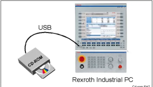
Certain Rexroth industrial PCs (e.g. those in a switch cabinet) include a CD-ROM drive.
To execute Setup, a portable CD-ROM drive can be connected to the USB port of the industrial PC.
Cd-rom.FH7
Fig. 2-1: Locally connected CD-ROM drive
CD-ROM Drive in a Network
If the industrial PC is connected to a network, the CD-ROM drive of any PC incorporated in the network can be used for setup (see "Network settings" chapter).
1. Install the Microsoft network.
2. Enable the CD-ROM drive of the connected PC.
Netz.FH7
Fig. 2-2: CD-ROM drive in a network
Internal CD-ROM drive External CD-ROM drive
Software Installation Carrying Out Setup
2-3
Installing Rexroth IndraWorks
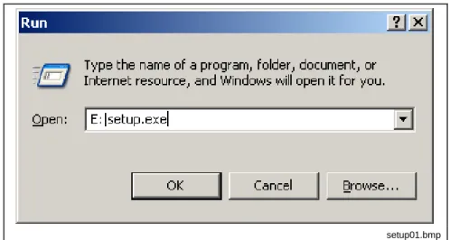
In this description, we assume that you use CD-ROM drive "E" for setup. 1. Insert the CD into the CD-ROM drive.
2. Click Run in the Start menu.
3. Type the letter for the drive together with ":\SETUP.EXE".
When you install your system from a CD-ROM, enter, for instance, "E:\SETUP.EXE".
setup01.bmp
Fig. 2-3: Windows XP “Run” dialog box
4. Then click OK or confirm with <Enter>.
5. Select the language for the setup program.
setup02.bmp
Fig. 2-4: Language selection The setup program is loaded.
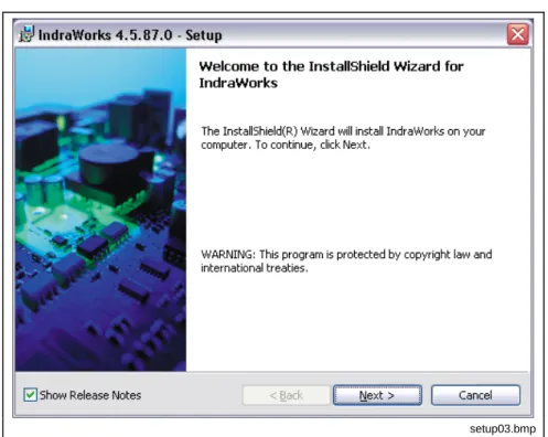
6. A message appears if release notes exist for the current version. If you select "Display Release Notes", the corresponding PDF document opens after you press Next >.
2-4
Carrying Out Setup Software Installationsetup03.bmp
Fig. 2-5: Note regarding release notes
7. Exit Acrobat Reader after reading the release notes and heed the remaining setup instructions.
8. Accept the conditions of the license agreement.
setup04.bmp
Fig. 2-6: License agreement
9. Confirm by pressing Next > until the "Customer Information" dialog box is displayed.
Software Installation Carrying Out Setup
2-5
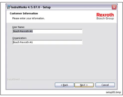
setup05.bmp
Fig. 2-7: Customer information
10. Enter the name and company of the rightful user and press Next >; this brings you to the selection of the desired setup directory (target folder).
11. In the dialog box, select the drive and the destination folder where the user interface is to be installed. Pressing Next > brings you either to the Start dialog box for the actual installation procedure or to the dialog boxes for the additional MTX configuration (target name, IP address).
Note: The hard disk of a standard BTV has two partitions (C: NTFS file system, D: FAT32 file system). The interface must be installed on drive C.
setup06.bmp
2-6
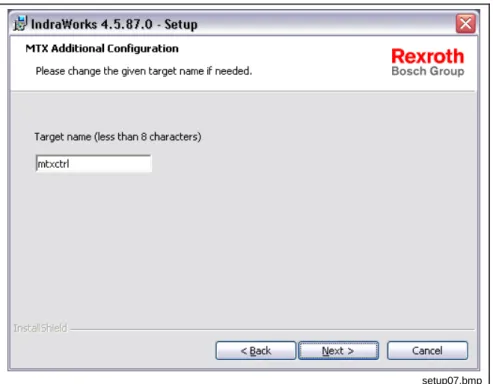
Carrying Out Setup Software Installation12. Entry dialog box for the MTX target name. “mtxctrl” is provided as the default entry. The MTX target name can have max. 7 characters. Pressing Next > brings you to the IP input dialog box.
setup07.bmp
Fig. 2-9: Entering the target name
13. Enter the IP address for control card CMP 40/CMP 60. Default: 192.168.142.250. Pressing Next > brings you to the Start dialog box for the actual installation procedure.
setup08.bmp
Fig. 2-10: IP address of the CMP 40 / CMP 60
Software Installation Carrying Out Setup
2-7
setup09.bmp
Fig. 2-11: Starting the installation procedure
The installation procedure now starts. The progress of installation is displayed in a progress bar.
setup10.bmp
Fig. 2-12: Progress of the installation procedure
2-8
Carrying Out Setup Software Installationsetup13.bmp
Fig. 2-13: Request to change the CD
16. When requested, complete the setup by clicking Finish.
After completion of the copying process, you will be prompted to restart Windows.
setup11.bmp
Fig. 2-14: End of the installation procedure
Note: You must restart Windows and/or your computer before you can use the program.
After startup, the system files are updated and registrations, if required, are executed.
This completes the setup.
Executing Setup without Control Card CMP 40/CMP 60 (Emulation)
The installation of Rexroth IndraMotion MTX as an emulation occurs as described above. The only difference is that the dialog boxes for entering the target name and the IP addresses do not appear.
Software Installation Carrying Out Setup
2-9
2.3
Further Steps Before Commissioning an MTX Control
Firewall Settings
NFS Server and TeleBugger
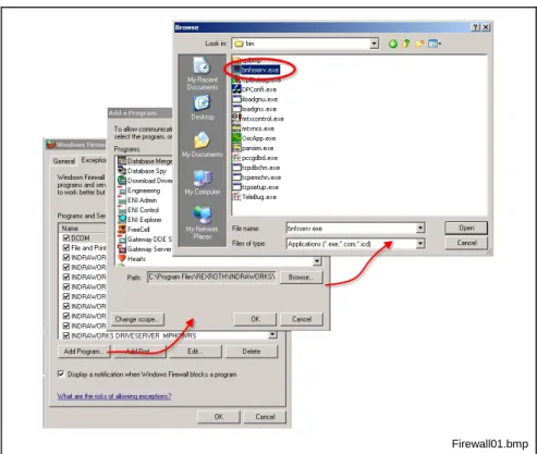
Firewall settings must be made before commissioning. To permit the mounting of directories on third-party computers and to allow remount debugging if errors occur, exceptions must be set for these programs. These programs are “bnfsser.exe” and “TeleBug.exe” in directory ...\Rexroth\IndraWorks\mtx\bin.
The exceptions are set as follows:
1. In the Start menu, open Settings – Control Panels – Windows
Firewall.
2. Activate tab “Exceptions” and click “Program ...”.
3. Click “Browse” and switch to directory “...\Rexroth\IndraWorks\mtx \bin”.
Firewall01.bmp
Fig. 2-15: Setting “bnfsser.exe” as an exception 4. Select file “bnfsser.exe” and open it. 5. Confirm the dialog box by pressing “OK”.
This transfers the file to the list of exceptions. 6. Use the same procedure for file “TeleBug.exe”. This removes these programs from the firewall.
CMP 40/CMP 60
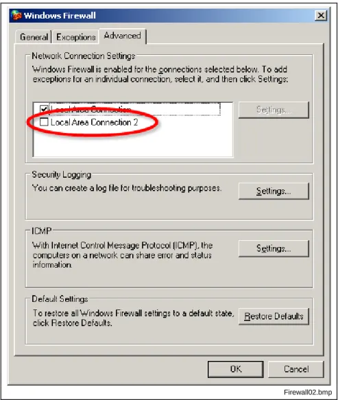
Control card CMP 40/CMP 60 must be manually removed from the firewall.
1. In the Start menu, open Settings – Control Panels – Windows
Firewall.
2-10
Carrying Out Setup Software InstallationFirewall02.bmp
Fig. 2-16: Advanced firewall settings
3. Deactivate entry “LAN connection 2” by removing the checkmark. 4. Accept the settings by pressing “OK”.
This removes control card CMP 40/CMP 60 from the firewall.
Updating the Network Driver
The network driver for CMP 40 / CMP 60 establishes communication between the CPM60 control card and the IPC. The driver for CMP 40 / CMP 60 is installed as follows:
• Open the Windows "Device manager" via "Start – Settings – Control
Panel – System, tab "Hardware".
The new hardware "Network adapter" which was detected by Windows should be marked with a yellow exclamation mark in the Device Manager.
• Click the right mouse button on the network adapter and select menu "Update driver...".
The "Hardware update wizard" opens.
• Select the option "Install software from a list or certain source" in the hardware update wizard and press ”Continue”.
• Then select the option "Find a corresponding driver in this source" in the "Search and installation options" and enter path "LW\Program Files\Rexroth\IndraWorks\MTX\drivers" in "Find also in following sources". Exit the dialog box by pressing "Next".
Software Installation Carrying Out Setup
2-11
The driver is now installed; after installation, it is entered under Network adapters as "PCC-P Numerical Controller".
Note: The control absolutely must be restarted after installation of the network driver.
Afterwards, the IP address for the network adapter must be entered. See sections "Network Settings" and "IP Addresses".
Note: If the control was started for the first time after installation of the CMP 40 / CMP 60 control hardware, the wizard “New hardware found" opens automatically (same procedure as described above).
After updating the IndraMotion MTX, the network driver should be updated.
Firmware Download
It is necessary to check if downloading firmware is necessary. The firmware version already installed must be compared with the version to load and, if necessary, the new firmware must be loaded. You can view the currently installed firmware version in the menu of the CMP 60 control under "? - Firmware Version".
Firmware Download is executed with the CMP 60 control. The control can be opened via "Start – Program Files – Rexroth – CMP60 – CMP60
Control".
• Firmware Download can be executed with the menu bar via
command "Commands\Download". Alternatively, the icon for Firmware Download (topmost icon line, at the extreme left) can be used to call the Download Manager.
• Select the entry "Monitor - Bootloader" in the Firmware Download dialog box. The password is "Software". Then exit the dialog box by clicking “OK".
• Select the entry "Firmware" in the Firmware Download dialog box. Then exit the dialog box by clicking YES.
• After a successful download, execute a reset.
After the software reset has been triggered, the CMP control starts up and stops at a "red zero".
2-12
Carrying Out Setup Software Installation2.4
Uninstalling Rexroth IndraWorks
Rexroth IndraWorks is uninstalled using the operating system (via Start
menu - Control Panel - Software). Select "IndraWorks" as the program
to be uninstalled. The Rexroth IndraWorks installation CDs are not required for this. After uninstallation, you are asked whether ALL the data within the Installation folder are to be moved to the trash.
CAUTION
Loss of user data!
⇒ Make sure that you save the user data before
uninstalling the software if you want to keep them.
setup12.bmp
Fig. 2-17: End of the uninstallation procedure
After completion of the uninstallation process, you will be prompted to restart Windows.
Note: In order to update the system files, restart Windows and/or your computer.
After startup, the system files are updated. This completes the uninstallation process.
Uninstallation using operating system
Software Installation Data Archival/Backup
3-1
3 Data
Archival/Backup
3.1
Archiving the IndraWorks Project
Note: Archiving the IndraWorks project also includes the archiving of NC data.
• Start archiving in IndraWorks in Project -Archiving.
• Select the project to archive (normally the last active project) and press "Continue".
• Determine the name and path of the archive and press "Continue".
• Check the details and continue with "Finish" if all settings are correct.
• MTX archiving is now started.
• Confirm the welcome dialog box with "Continue".
• Select the portions to be archived and confirm with "Continue".
Note: If archive part "Remanent data of PLC" is selected, the PLC should be stopped via CMP60 control before starting archiving. "Software" is the password to stop the PLC by pressing the "PLC" button.
• Confirm the information by pressing "Finish".
• Now the MTX archive is created.
• Exit the dialog box "Create MTX archive - summary" with "Close".
• Now the project archive is created.
• After successful archiving, a dialog box with a summary is displayed.
Note: The project path of the archived IndraWorks project, as well as the name and path of the archive, should be noted! This information is necessary for subsequent restoring.
3.2
Archiving of Data that are Not Project-Specific
Note: These data are PLC data as well as GSD files and PLC libraries if they are not saved project-specifically but target-specifically.
• Special GSD files go to folder "C:\Program Files\Rexroth\IndraWorks\ IndraLogic\Targets\<target name>\userconfig"
• Special PLC libraries go to folder "C:\Program Files\Rexroth\ IndraWorks\IndraLogic\Targets\<target name>\lib" or "C:\Program Files\ Rexroth\IndraWorks\IndraLogic\Targets\Config"
Software Installation Executing a Software Update of IndraWorks
4-1
4
Executing a Software Update of IndraWorks
4.1
Executing an Update of IndraWorks
CAUTION
Loss of user data!
⇒ Save the user data before a software update.
In this description, we assume that you use CD-ROM drive "E" for installing the update.
1. Insert the CD into the CD-ROM drive. 2. Click Run in the Start menu.
3. Type the letter for the drive together with ":\SETUP.EXE".
When you install your system from a CD-ROM, enter, for instance, "E:\SETUP.EXE".
setup01.bmp
Fig. 4-1: Windows XP “Run” dialog box
4. Then click OK or confirm with <Enter>.
5. Select the language for the setup program.
setup02.bmp
4-2
Executing a Software Update of IndraWorks Software InstallationThe setup program is loaded.
6. A message indicating that an update of IndraWorks is being executed appears. If you answer the query with Yes, the Info screen for executing the update appears.
setup14.bmp
Fig. 4-3: Message indicating IndraWorks update
7. Info screen for updating IndraWorks. Pressing Next> brings you to the actual initial screen of the update procedure.
setup15.bmp
Fig. 4-4: Info screen for updating IndraWorks
8. Initial screen for the update procedure. When you press Install >, the update procedure is started; a status screen that shows the current update status appears.
Software Installation Executing a Software Update of IndraWorks
4-3
Setup16.bmp
Fig. 4-5: Status screen for the update procedure
setup17.bmp
Fig. 4-6: Status information
4-4
Executing a Software Update of IndraWorks Software InstallationAfter completion of the update process, you will be prompted to restart Windows.
setup11.bmp
Fig. 4-7: End of the update procedure
Note: You must restart Windows and/or your computer before you can use the program.
After startup, the system files are updated and registrations, if required, are executed.
Software Installation Restoring Data
5-1
5 Restoring
Data
5.1
Restoring Data That Are Not Project-Specific
Note: These data are PLC data as well as GSD files and PLC libraries if they are not saved project-specifically but target-specifically.
• Copy these special GSD files from the backup folder to folder "C:\Program Files\Rexroth\IndraWorks\IndraLogic\Targets\<target name>\userconfig".
• Copy these special PLC libraries from the backup folder to folder "C:\Program Files\Rexroth\IndraWorks\IndraLogic\Targets\<target name>\lib".
5.2
Restoring the IndraWorks Project
• Start IndraWorks Engineering.
• In IndraWorks, execute Project - Restore.
• Select the project to restore and press "Continue".
• Determine the destination directory and press "Continue".
Note: The destination directory for the IndraWorks project must correspond with the source directory of archive. The project paths must be identical before archiving and after restore. See the second note in chapter 3.1.
• Check the details and continue with "Finish" if all settings are correct.
• Project restoring is now started.
• After successful restoring, a dialog with a summary is displayed.
• Confirm this dialog with "Close".
• Open the restored project immediately with IndraWorks.
• Start "Restore" in the IW project under Motion.
• MTX archive restoring is now started.
• Confirm the welcome dialog box with "Continue".
• Select the MTX archive to restore (here, select only archive part "User FEPROM") and confirm with "Continue".
• Confirm the information by pressing "Finish".
• Now the MTX archive is restored.
• Exit the dialog "Restore MTX archive - summary" with "Close".
• Trigger "NC restart" in the IW project under Motion.
• Start "CMP60 Control" after complete restart.
• Switch to "Start up mode 6" and trigger a soft reset (SR).
• Switch to "Start up mode 0" and stop the PLC via "PLC button". The password to stop the PLC is "Software".
5-2
Restoring Data Software Installation• Start "Restore" in the IW project under Motion.
• MTX archive restoring is now started.
• Acknowledge the welcome dialog box with "Continue".
• Select the MTX archive to restore, select all archive parts except the "User FEPROM" and confirm with "Continue".
• Confirm the information by pressing "Finish".
• Now the MTX archive is restored.
• Exit dialog box "Restore MTX archive – summary" by pressing "Close".
• Trigger "NC restart" in the IW project under Motion.
• Trigger a "Download" in the IW project under HMI BTV xxxx.
• Confirm the confirmation message with "OK".
• Start IndraLogic in the IW project under Logic.
Software Installation IP Addresses
6-1
6 IP
Addresses
6.1 Overview
Each basic PC device contains
• a CMP 40 / CMP 60 plug-in card with an internal network connection in a separate subnet
• an Ethernet connection.
Example:
Einsteckkarte.tif
Fig. 6-1: Plug-in card in basic PC device
6.2
Configuration of Communication Interface
The data exchange between the basic PC device and the CMP 40 / CMP 60 plug-in card takes place using TCP/IP.
The CMP 40 / CMP 60 plug-in card and the network adapter are treated as an internal subnet with fixed IP addresses.
During configuration, the CMP 40 / CMP 60 plug-in card is assigned a fixed IP address which makes it possible for the basic PC device to communicate with this card. In addition, a default setting is assigned to the symbolic name for the CMP 40 / CMP 60 plug-in card.
⇒ Check and make note of the settings if changes are to be made to the current IP addresses.
6-2
IP Addresses Software InstallationNote: All following settings correspond to the Setup defaults.
Setting the IP Address of the Network Adapter
Proceed as follows to check or adjust TCP/IP settings for the network adapter of the CMP 40 / CMP 60 plug-in card:
1. Select the Windows XP menu: Start – Settings – Network
Connections.
2. Choose LAN connection "PCC-P Numerical Controller". 3. Choose File – Properties.
4. Choose "TCP/IP Internet protocol". 5. Press the "Properties" button.
6. Check the settings for the IP address and the subnet screen.
• The IP address is: 192.168.142.249
• The subnet mask is: 255.255.255.0
IP-Adresse_NW-Adapter.tif
Fig. 6-2: IP Addresses
Note: If the IP addresses mentioned above differ from the defaults in the standard installation, take note of the current IP addresses for the next software update so that you can adapt your control to the local network.
Software Installation IP Addresses
6-3
Setting the IP Address of the CMP60 Plug-In Card
The CMP 40 / CMP 60 plug-in card is known as “PCC-P Numerical Controller” in the system.
Proceed as follows to check or adjust the IP addresses for the CMP 40 / CMP 60 plug-in card:
1. Select the Windows XP menu: Start – Settings – Network
Connections.
2. Choose LAN connection "PCC-P Numerical Controller". 3. Choose File – Properties.
4. Press the “Configure” button. 5. Select tab "Advanced".
6. In the "Property" window, check and, if necessary, adjust the following entries.
• PCC-P Default Gateway: The default address of the network
adapter is: 192.168.142.249. It must always be located in the following subnet.
• PCC-P IP Address: The default IP address is: 192.168.142.250
• PCC-P Name: Symbolic name of the plug-in card installed in "Setup" (default: "mtxctrl").
• PCC-P Subnet Mask: The default subnet is: 255.255.255.0
IP-Adresse_Einsteckkarte.tif
6-4
IP Addresses Software InstallationBasic PC Device Ethernet Connection
If the basic PC device is also connected to a network, communication takes place using the Ethernet connection via TCP/IP. A fixed IP address is also required for this connection.
Note: Check and make note of the TCP/IP and network card settings for the existing hardware components if changes are to be made to the current IP addresses.
The IP addresses may have to be adjusted if:
• a search is made for another IP address for the basic PC device during a PNC software update.
• several basic PC devices are located in a company network and additional basic PC devices will be added using PNC-P.
• the address of the company network has changed.
• the entries were overwritten after reinstalling Windows on the basic PC device.
Software Installation Network Settings
7-1
7 Network
Settings
7.1 General
Information
You can obtain detailed information about the TCP/IP protocol or about the network settings from your network administrator and/or in the Microsoft operating system documentation.
Note: It is recommended that your network administrator make all network-related settings.
7.2
Enabling a CD Drive in a Network
Before a CD-ROM drive can be accessed from another computer (client PC), it must be enabled, i.e. permission to use this unit on the computer in which the drive is installed (server PC) must have been granted.
In Windows, the administrator can set up “groups” with a “user profile” for corresponding privileges for enabling network drives. If no such group has been defined, only the administrator can carry out enabling.
1. Insert the CD with the software into the CD-ROM drive of the server PC.
2. Click the symbols "My Computer" and "CD-ROM".
3. In menu File – Enablement and Safety..., choose "Enabled as".
4. Choose tab "Enable".
5. Activate "Enable this folder in the network". 6. Enter “CD” as the enablement name.
7-2
Network Settings Software InstallationFreigabe.tif
Fig. 7-1: Enabling a network drive
Software Installation Network Settings
7-3
7.3
Connecting to a Network Enabled in the CD-ROM Drive
The computer to which access to the CD-ROM drive is to be assigned (client PC) must connect the enabled CD-ROM drive of the server PC with its file system (directory).
Search for the enabled CD directory “CD” on the server PC: 1. Choose Network environment.
2. Press the "Search" button in the toolbar.
3. Enter the name of the server PC (e.g. IPCREXIND01) and click the "Search" button.
4. Click the symbol of the server PC and search for the enabled drive "CD".
5. Click “CD” and choose File – Connect network drive...
6. Now assign a drive letter (e.g. "Z:") to "CD". If this is set up by the administrator, access to the server PC requires a password before a network connection can be established.
7. Insert the CD-ROM into the drive.
8. In Windows Explorer, check whether the contents of the CD are read.
LW_verbinden.tif
7-4
Network Settings Software Installation7.4
Access to the CMP 40/CMP 60 from an External PC
(Routing)
Overview
Applications such as IndraWorks or IndraLogic can access a basic PC device with a CMP 40 / CMP 60 plug-in card from any network PC via Ethernet. In this case, a route must be entered on the network PC.
Zugriff_extern.tif
Fig. 7-3: Example of external access
Conditions
The network PC and the basic PC device must be located in the same subnet. Example (subnet 142.2.25.0):
• Network PC: IP address 142.2.25.20
• Basic PC device: IP address 142.2.25.25
"IP forwarding" must be activated in the basic PC device.
• Automatic entry in the Registry for installation of the CMP 40/CMP 60 software.
Entering a Route
A route for PNC-P subnet 192.168.142.0 must be entered on the network PC.
⇒ To do this, run the following MS-DOS command line:
route add -p <subnet address> MASK <subnet mask> <IP address of basic PC device>
route add -p 192.168.142.0 MASK 255.255.255.0 142.2.25.25 (Parameter "-p" stands for permanent route)
Software Installation MTX Control
8-1
8 MTX
Control
8.1 Introduction
The MTX Control tool is a commissioning and diagnostic program for PC-based IndraMotion MTX CNC controls. It is used to configure, control and monitor CNC module IndraControl CMP 60. MTX Control is installed on the user panel as a Windows service; it starts automatically when the PC is switched on. When MTX Control is active, the following symbol appears in the task bar:
Mtxbit.gif
Fig. 8-1: "MTX Control" symbol
MTX Control monitors the status of the control and displays basic status information. MTX Control is opened by:
• double-clicking the MTX Control symbol in the task bar, or
• opening the contextual menu by clicking the right mouse button and then choosing menu item View.
8.2 Overview
After MTX Control is opened, the MTX Control window is displayed as shown below.
MainPage.gif
Fig. 8-2: Start window
The most important operating and display elements are described in the following:
Display of the Startup Phase
• In normal operation (Ready), the display RUN appears on a green background.
• While the MTX is starting up, the individual phases that the control goes through, and thus the progress of the control startup, are displayed (see sect. 8.4 Power-up).
8-2
MTX Control Software InstallationGeneral Status Information
Certain basic status information is summarized in a table and is indicated by green, red or gray LEDs:
• MTX-Control error
In the case of serious errors due to incorrect installation or to a hardware defect, an error code, incl. plain text, is issued.
• TCP/IP
A green LED indicates that TCP/IP is working without errors. TCP/IP communication problems are indicated by a red LED.
• Fieldbus
A green LED indicates that the field bus is working properly. Field bus problems are indicated by a red LED.
• UPS
A green LED indicates that the UPS is working properly. A red LED indicates an error. If a UPS does not exist, a gray LED is shown.
Status Line
The following information is displayed in the status bar:
• IP address
The IP address entered in the Windows network configuration is displayed. Changes to this address can be made in the Windows control panel. If you want to change the default settings generated during installation, it is recommended that the network administrator carry this out.
• Working mode
--- Monitor program stuck or does not exist
monitor running Monitor program running
download active Firmware download running
software downloaded Firmware download complete
software started Normal operation
Fig. 8-3: Working mode
Tool Bars
User level 2 (Service/Development) is required to access the functions of the first tool bar. The functions can be accessed by clicking the mouse or by pressing key combination Shift + F1 to Shift + F5. In some functions, the symbol changes according to the switch state.
Firmware Download (also see sect. 8.8 Firmware Download)
The firmware is reprogrammed. This occurs, for example, when updating to a newer firmware version.
MTX Shutdown
The MTX is shut down properly. Then the internal data are backed up (option). The data are backed up by creating the two files MtxpRoot.pxf and MtxpSram.dat in the Home directory of the MTX.
Hardware Reset
This triggers a hardware reset, which is followed by a startup of the MTX. Backup mode ON (default)
The data are backed up after the control is shut down. Backup mode OFF
Data backup is switched off. If it is determined during the shutdown that the permitted battery voltage is too low, the data are backed up even if this is OFF.
Software Installation MTX Control
8-3
UPS automatic mode (default)
MTX Control automatically detects a UPS. If a UPS exists, UPS mode is activated; otherwise, UPS mode is deactivated. Bosch Rexroth UPSs are detected automatically.
UPS mode ON
If a third-party UPS that cannot be detected automatically is used, UPS mode can be switched on manually.
UPS mode OFF
Startup mode (also see 8.5 Startup Mode)
Fig. 8-4: Functions of the first tool bar
The functions of the second tool bar can be accessed mainly in user level 1 or 2 (MTB or Development/Service). The functions can be accessed by clicking the mouse or by pressing function keys F1 to F12. In some functions, the symbol changes according to the switch state.
Call online help
Detailed display of the MTX firmware version Software reset followed by startup
Read in archive (see section 8.7 Archive Function). Create archive (see section 8.7 Archive Function).
Incorporate (mount) external file systems (see section 8.9 Incorporating File Systems (Mount)).
Configuration of the Ethernet interface (see section 8.11 Ethernet Interface). Exit MTX Control
The control continues to run. This function should not be used because, if MTX Control is inactive when the user panel is shut down, a shutdown of the MTX is not triggered and the data are not backed up.
Remote debugger is activated (green)
Remote debugger is exited (red) PLC is started (green)
PLC is stopped (red)
PLC outputs are disabled
PLC outputs are enabled PLC fixing is cancelled (green)
PLC is fixed (red)
Fig. 8-5: Functions of the second tool bar
Main Menu
All the functions that are provided by the two tool bars can also be accessed from the main menu. In addition, the main menu provides a few additional commands. The commands of the main menu, with brief descriptions, can be found in section 8.3 Main Menu.
8-4
MTX Control Software Installation8.3 Main
Menu
The MTX Control main menu contains all the functions that are provided by the tool bars, as well as a few additional functions that are required only in exceptional cases. The following table shows the menu structure and explanations for the individual functions:
Menu entry Submenu Explanation
Firmware Download See section 8.8 Firmware Download.
Shutdown Proper shutdown of the MTX followed by data backup.
Hardware Reset Triggers a hardware reset, which is followed by a startup of the MTX. Load boot parameters See section 8.12 Boot Parameters.
Cleanup Memory Deletes the DRAM with the exception of the monitor and boot loader memory
areas. This function is required only in exceptional cases in Development.
Cleanup SRAM Deletes the SRAM (root file system, permanent CPL variables, residual PLC
data, residual system data). This function is required only in exceptional cases.
Cleanup FEPROM Deletes the FEPROM (firmware, FEPROM file system). This function is
required only in exceptional cases.
Software Reset Triggers a software reset, which is followed by a startup of the MTX.
Archive restore See section 8.7 Archive Function.
Archive create See section 8.7 Archive Function.
Mount Incorporate (mount) external file systems (see section 8.9 Incorporating File
Systems (Mount)). Commands
Ethernet Configuration Configuration of the Ethernet interface (see section 8.11 Ethernet Interface).
Menu entry Submenu Explanation
PLC Run/Stop Start and stop the PLC
Clear Force Delete PLC fix
Output Enable/Disable Enable or disable PLC outputs Commands
Show System Errors Display critical system errors
Set Level 0 Reset to user level 0 (see section 8.13 User Level).
Password
Change Change the password (see section 8.13 User Level).
Developer toolbar Show/hide the tool bar for Service/Development
Toolbars
MTB toolbar Show/hide the MTB tool bar
Tools Remote Debugger Activate and exit the remote debuggers
Hide Window Close MTX Control
Foreground Move the MTX Control window to the foreground or the background
Window
Default size Reset to default window size
Info about MTX Control
Display the software version of MTX Control
Firmware Version Detailed display of the firmware version
Software Options Display the applied software options
Hardware Info Hardware information (PCB number, version, serial number)
?
Online Help Call online help
Software Installation MTX Control
8-5
8.4 Power-up
The MTX starts up if the user panel is switched on or if a software or hardware reset is activated. The startup occurs synchronized in 12 phases that are displayed in MTX Control:
P: -3
Determines the existing hardwareP: -2
RTOS startup, configure file systemsP: -1
Start RTOS monitorP: 1
Initialize basic NCS communicationP: 2
Initialize TCP/IPP: 3
Initialize BAPAS databaseP: 4
SERCOS initializationP: 5
Start NCB-TCP serverP: 6
Start SERCOS startupP: 7
Mount the NFS file systemsP: 8
Synchronization with SERCOSP: 9
Enable NCB-TCP server (communication with user interface)RUN
Normal operationFig. 8-7: Display of startup phases
The display differs as follows in the case of critical system errors, boot panic errors and an active shutdown of the MTX:
SF
A critical system fault has occurred.BP
A boot panic error has occurred.SD
Shutdown activeFig. 8-8: Error status display
If the monitor is active, the monitor status is displayed:
M: A
Ethernet activeM: 8
Ethernet inactiveM: L
Loading activeM: d
Deletion activeM: NMI
The monitor is in an NMI routine (error or power down)M: E
Internal error in monitor8-6
MTX Control Software Installation8.5 Startup
Mode
The startup mode determines the behavior of the MTX during startup. A change to the startup mode becomes effective only during the next startup.
Startup mode Meaning
0
Normal operationAll existing data and file systems are retained. The root file system is checked during startup. If adefective file system is detected, a critical system error is displayed. A new (empty) root file system is automatically created during the next startup.
1
PLC stopThe behavior corresponds to startup mode 0 with the difference that the PLC remains in the STOP state and the PLC user program is not processed.
2
Reloading of the PLC boot projectThe PLC boot project is loaded from the user FEPROM. Any PLC boot project that exists in theroot file system is discarded. Otherwise, the behavior corresponds to startup mode 0.
3
Protected startupIn extreme cases, faulty machine parameter settings can make it impossible to start up a control. Startup mode 3 is used to carry out a startup in this situation, regardless of the set machine parameters. A startup with the minimum configuration occurs and the set machine parameters are ignored. After the startup, the invalid machine parameter settings can be corrected and a new startup with startup mode 0 can be carried out.
4
Delete permanent CPL variablesThe permanent CPL variables are deleted; otherwise, the behavior corresponds to startup mode 0.5
Cold startThe power-up management logic is not run; otherwise, the behavior corresponds to startup mode 0.
6
BootstrapA new root file system is created; as a result, all the data of the old file system are lost. If an intactuser FEPROM file system exists, the PLC boot project and configuration data are loaded from there.
7
Creation of the user FEPROM file systemThe user FEPROM is created; as a result, all the data of the old file system are lost. This is required, for example, if a user FEPROM file system is defective. The root file system remains. The permanent CPL variables will be deleted.
8
Identical to startup mode 99
Debug modeThis is the usual debugging mode if the control should not automatically start up after a reset. After the basic monitor is initialized, the boot loader is activated and the subsystems are loaded
automatically.
10
Debug mode (without automatic loading)After the basic monitor is initialized, the boot loader is activated. Then loading can take place using TCP/IP.
11
Debug mode (without activating the boot loader)The basic monitor is initialized. Then loading can take place using TCP/IP.
12
Identical to startup mode 1513
Identical to startup mode 1514
Identical to startup mode 1515
Debug mode (basic monitor start)Only the basic monitor is activated.Software Installation MTX Control
8-7
8.6 Data
Backup
CNC module CMP 60 has a non-volatile memory: the flash EPROM memory is permanent; no buffering is required. During the firmware download, the firmware and the FEPROM file system is copied to the flash EPROM. These areas change only during a firmware download; on the other hand, the user FEPROM is designed to be used to store configuration data – it can be changed at any time.
The SRAM is designed for user data. Residual PLC data, permanent CPL variables and residual system data are stored here. Furthermore, the root file system is located in the SRAM. It contains parts programs and tables as well as any other user data. Since the SRAM is battery-buffered, the data are retained even after the system is switched off. As an additional safety feature, the data in the SRAM are backed up when the MTX is shut down:
cmp60save.gif
Fig. 8-11: Data backup
• File mtxproot.pxf contains the entire root file system.
• File mtxpsram.dat contains residual PLC data, permanent CPL
variables and residual system data.
Backing up the data in the SRAM can be suppressed by switching off backup mode (see section 8.2 Overview, Tool Bars).
The consistency of the data in the SRAM is checked when the system is switched back on. The accuracy of the consistency check depends on the existence of a UPS. Normally, UPS mode Automatic (see section 8.2 Overview, Tool Bars) is active, i.e. the UPS is detected automatically. If a UPS exists, a checksum is generated for the data areas in the SRAM when shutting down. If a UPS does not exist, a checksum is not calculated when shutting down. As a result, a checksum is not checked during the next startup; instead, only a simple consistency check is carried out.
8-8
MTX Control Software InstallationIf there are no errors, the MTX starts up normally. If there is an error, startup does not occur; instead, the user is informed of the fault situation:
MtxHochlaufError.gif
Fig. 8-12: Error situation
The backup files that were created last are indicated as follows:
? File exists and contains no errors
--- File does not exist
∑ File has a checksum error
HW Hardware incompatibility
(can occur after replacing hardware) Fig. 8-13: Indication of backup files
Software Installation MTX Control
8-9
The interrupted startup can be continued with one of the following options. The password for the user level is required for this:
• Clean startup:
control startup without using the existing backup files.
• Startup with the last saved data files:
control startup with the existing backup files (if these contain no errors).
• No startup
No startup occurs; the monitor is activated.
If the HELP button is pressed, a note with the following explanations is issued:
MtxHochlaufHelp.gif
8-10
MTX Control Software InstallationAfter the desired start options have been selected and the START button is pressed, another message box is displayed:
MtxHochlaufInfo.gif
Fig. 8-15: Message box
The startup is carried out by pressing button Continue.
CAUTION
⇒ Regardless of the selected start option, check the MTX data after a successful startup. Invalid or expired data can cause personal injury or material damage to the machine, the drives or the workpiece. As a result, it is absolutely required that parts programs, ZO tables, correction tables, tool tables, as well as permanent CPL variables, residual PLC data and system files be checked!
8.7 Archive
Function
The archive function allows you to save the MTX user data and to restore them at a later point in time. The archived data are saved to a mounted directory in the form of an archive. If needed, the archive can be read to restore all the data.
• An archive is generated using the menu (Commands/Archive create) or directly using symbol .
• An archive is read to restore data using the menu
(Commands/Archive restore) or using symbol .
Note: Parts programs and the PLC must be stopped before an archive can be generated or restored.
Software Installation MTX Control
8-11
The data can be archived/restored either wholly or selectively. The data areas are selected in the subsequent window:
ArchivePage.gif
Fig. 8-16: Data area selection
• User - FEPROM
All the files that are stored in the user FEPROM
• RAM - Filesystem
All the files that are stored in the root file system
• Machine parameters MTX machine parameters • Tool Tables MTX tool tables • Permanent CPL-Variables Permanent CPL variables • Remanent PLC data Residual PLC data • System data MTX system data
After pressing the OK button or the Enter key, another dialog box opens in which the name and path of the archive (extension = .tar) is entered. The archive is saved to a mounted directory.
The dialog box is closed if the Cancel button or the Esc key is pressed. Pressing OK starts the archiving procedure, which can take a few minutes. Any errors that occur are recorded in a log file, which is automatically displayed when archiving is complete.
8.8 Firmware
Download
Firmware Download is used to update the MTX firmware. This is necessary, for example, after you have updated the MTX software on your user panel.
The firmware is transferred from the hard disk to the MTX and is saved to the flash EPROM. Downloading is started using the menu (Commands/Firmware Download) or directly using symbol .
8-12
MTX Control Software InstallationNote: The user data should be archived before executing Firmware Download. See section 8.7 Archive Function to find out how to generate an archive.
Note: All parts programs must be stopped before executing Firmware Download. The PLC must also be brought into the Stop state.
The following message explicitly notifies the user that the MTX will be stopped before Firmware Download:
Warning1Page.gif
Fig. 8-17: Alert message
After the note has been acknowledged by pressing the YES button, the components that are to be loaded are selected. Normally, only the first component, i.e. only the firmware, needs to be selected.
DownloadSelPage.gif
Software Installation MTX Control
8-13
The selection is also completed by pressing the OK button; the actual loading procedure starts then. The following display appears during the loading procedure:
DownloadPage.gif
Fig. 8-19: Loading process
After a successful loading procedure, the MTX must be restarted using Hardware Reset.
If errors occur during Firmware Download, they are logged in file mtxcontrol.tlg. The portion of the file that informs the user of errors that have occurred appears as follows:
DownloadErrPage.gif
Fig. 8-20: Error message
8.9
Incorporating File Systems (Mount)
In addition to the internal root file system, the MTX offers the possibility of incorporating external file systems using NFS. NFS (Network File System) is a standard used to distribute file system resources in the network. An NFS server provides one or more file systems in the network (export) that can be mounted (import) by NFS clients.
It is possible to mount any directory onto the hard disk of the local user panel or a USB memory stick, a disk drive or a CD/DVD drive on the USB port of the user panel in the internal directory tree of the MTX. On the other hand, directories on external PCs (e.g. a file server) that are connected via the network to the local user panel can be incorporated. If a standard installation has been made, directory c:\mnt is mounted and the control is attached in the file system under mount point /mnt.
8-14
MTX Control Software InstallationFurther file systems are incorporated using the menu (Commands/Mount) or directly using symbol .
MountPage.gif
Fig. 8-21: “Mount” dialog window
The left side of the dialog box that then opens contains a list of the currently incorporated directories (MOUNT LIST). The right side (MOUNT PATH) shows the file system of the local PC. Additional directories that are also to be incorporated can be selected by navigating in this area.
Using the Dialog Box
Arrow Keys
Navigation in both areas
Double-click right mouse button
• In the MOUNT PATH area
The selected path is adopted in the list of incorporated directories. The list can contain up to 10 entries. If an existing entry is highlighted before the transfer, it is overwritten by the new path.
• In the MOUNT LIST area
The selected entry is removed from the list.
Ctrl+S
The same as double-clicking the right mouse button in the MOUNT PATH area.
Function Key F2
The properties of the entry highlighted in the list of incorporated directories can be modified. When changing the name, ensure that this always starts with a / and that the name does not already exist in another entry. If an error occurs, a corresponding error message is issued.
Other properties in addition to the name can be modified:
• r+
The selected directory is incorporated in read-only format. The data can be read from the MTX, but they cannot be modified.
•
r-The selected directory is incorporated in read and write format.
• c+
Activates the cache for this directory
•
Software Installation MTX Control
8-15
Function Key F5
Updates the display
Escape Key
Exits the dialog box. All changes are discarded.
Return Key
Adopts the changes and closes the dialog box.
Tab Key
• Switches between the MOUNT PATH and MOUNT LIST areas.
• Closes the Edit window for the name in table MOUNT LIST.
After the dialog box is closed by pressing Enter, the entered data are saved as boot parameters, i.e. the changes are saved in the boot parameter file and transferred to the MTX.
Note: The boot parameters are evaluated only during the next startup of the MTX, i.e. you must execute a software or hardware reset to let the new settings go into effect.
Note: Incorporating directories on external PCs, such as a file server in the user panel network, can be accomplished only by manually modifying the boot parameter file. You can find more information in section 8.12 Boot Parameters.
8-16
MTX Control Software Installation8.10 Operating a USB Stick on the MTX as a Mount Directory
Configuration
The root directory of a USB stick should be mounted. This is called "USB" on the MTX side.
Note: Mounting a subfolder to a USB stick is not recommended. This causes various errors when the stick is removed in connection with a soft reset.
USBStickMount.JPG
Fig. 8-22: Root directory of an USB stick mounted
MTX Boot Parameter
1. Adjust file ...\IndraWorks\mtx\mtxctrl\pccpboot307078.ini as follows.
#BPAR #STUPFILE
NFSMOUNT 192.168.142.249:/C/mnt /mnt rw c+ NFSMOUNT 192.168.142.249:/e /USB rw c-#ESTUPFILE #NET IPADDR 0.0.0.0 SNMASK 0.0.0.0 GWADDR 0.0.0.0 #ENET #EBPAR
Fig. 8-23: Additional line in pccpboot307078.ini
Note: Only one mount directory can be cached internally as "c+". All other mounts should be identified with "c-".
Software Installation MTX Control
8-17
2. Select menu item “Load boot parameter” in the MTX control.
USBStickMount_LoadBootParameter.JPG
Fig. 8-24: Load boot parameter
NFS Parameter
1. Adjust file ...\IndraWorks\mtx\bin\export.us as follows.
C:\mnt mtxctrl localhost E:\ mtxctrl localhost
Fig. 8-25: Additional line in export.us
2. Reload (right mouse button on symbol in the taskbar)
USBStickMount_Reload_NFS.JPG
Fig. 8-26: Reloading "export.us"
Executing an MTX Soft Reset (SR)
USBStickMount_SR.JPG
8-18
MTX Control Software Installation8.11 Ethernet Interface
CNC module CMP 60 has an on-board Ethernet interface.
The interface is configured using the menu (Commands/Ethernet
Configuration) or directly using symbol .
The current settings are displayed in the following entry screen.
EthernetPage.gif
Fig. 8-28: Entry screen
The displayed parameters IP address, Subnet screen and Standard gateway can be modified. The new values are adopted by pressing the
OK button. The entered data are saved as boot parameters, i.e. the
changes are saved in the boot parameter file and transferred to the MTX.
Note: The boot parameter will not be evaluated until the next startup of the MTX. A software or hardware reset must be executed so that the new settings can go into effect.
If the entry screen is closed by pressing Cancel, all the changes are discarded and the parameters remain as they were.
If the Ethernet interface is not configured, all parameters have a value of zero.
Note: The CMP 60 is integrated as a network card into the Windows operating system. As a result, from a logic point of view, two interfaces exist. The first interface uses the PCI bus. This interface is used mainly for communication with the MTX interface and with the PLC programming system. It is configured in the Windows Control Panel.
The second interface is the Ethernet interface on the CMP 60 module (on-board), whose configuration is described here.
8.12 Boot Parameters
The MTX boot parameters are located in file mtxpboot<PCB number>.ini in the Home directory of the control. (The PCB number can be determined using the menu entry in the main menu – also see section 8.3 Main Menu.) In every software or hardware reset, the boot parameters are read from this file and copied to the SRAM. Then startup occurs with the current boot parameters.
Software Installation MTX Control
8-19
If the mount parameters or the Ethernet interface configuration is changed, the set values are saved to the boot parameter file and are copied to the SRAM.
The boot parameter file contains information about the incorporated external file systems and the configuration parameters of the Ethernet interface. #BPAR #STUPFILE NFSMOUNT 192.168.142.249:/c/mnt /mnt rw c+ #ESTUPFILE #NET IPADDR 142.3.0.1 SNMASK 255.255.255.0 GWADDR 142.3.0.18 #ENET #EBPAR
The section starting with #STUPFILE is used to input the mount parameters; it is completed with #ESTUPFILE. An entry with keyword NFSMOUNT exists for every incorporated file system. The listed parameters depend on the entries made during installation. The example above applies to the default installation.
Another section is identified by #NET and #ENET. The Ethernet interface parameters are located in this section.
Note: To avoid the incorrect setting of parameters, the boot parameter file should not be modified manually. Modifications should be made only with the corresponding MTX Control dialog boxes (see sections 8.9 Incorporating File Systems (Mount) and 8.11 Ethernet Interface).
8.13 User Level
Numerous functions are password-protected to prevent access to unauthorized persons. MTX Control administrates three user levels:
• Level 0 (user):
functions that every user may use.
• Level 1 (machine manufacturer):
commands to control the MTX and the integrated PLC.
• Level 2 (service/development):
commands for specific stopping and starting of the MTX control (data loss possible).
Higher user levels automatically also have access to all the functions of the subordinate user level.
Changes to the user level always are in effect only until midnight. When the date changes, the user level is automatically reset to 0. An explicit reset can be carried out using the menu (Password/Set level 0).
If a function that is not permitted in the current user level is selected, a request for entering the password for the required user level appears; following is an example for user level 2:
8-20
MTX Control Software InstallationPasswordInputPage.gif
Fig. 8-29: Password entry
After the correct password has been entered and confirmed by pressing
Enter, the requested function is executed. The entry can be cancelled by
pressing Esc; in this case, the requested function is not executed.
The passwords defined by Bosch Rexroth can be changed at any time. This is accomplished using the menu (Password/Change). Then the following entry screen is displayed:
PasswordPage.gif
Fig. 8-30: Change password
Proceed as follows to change a password:
• Select box for password level (select the user level)
The user level for which the password is to be changed is set here.
• Enter old password
The password can be changed only by entering a valid password. Enter the current valid password here.
• Enter new password
After the new password has been entered, it must be entered again in the same window for confirmation. The text above the entry field changes from Enter new password to Verify new password. If the entries agree, the password change goes into effect by pressing the
OK button or Enter.
If Esc or the Cancel button is pressed, changing the password can be cancelled at any time.