AUSTRALIAN JOURNAL OF BASIC AND
APPLIED SCIENCES
ISSN:1991-8178 EISSN: 2309-8414 Journal home page: www.ajbasweb.com
Open Access Journal
Published BY AENSI Publication
© 2017 AENSI Publisher All rights reserved
This work is licensed under the Creative Commons Attribution International License (CC BY).
http://creativecommons.org/licenses/by/4.0/
To Cite This Article: Ankur Singhal and Singh., Investigation of Passive Optical System with Dispersion Compensation and Error Correction. Aust. J. Basic & Appl. Sci., 11(8): 80-86, 2017
Investigation of Passive Optical System with Dispersion Compensation and
Error Correction
1Ankur Singhal and 2Charanjeet Singh
1Research Scholar, IK Gujral Punjab Technical University, 144603. Jalandhar, India. 2Dept.of ECE, RBIENT, IK Gujral Punjab Technical University, 146104. Hoshiarpur, India.
Address For Correspondence:
Ankur Singhal, Research Scholar, IK Gujral Punjab Technical University, 144603. Jalandhar, India Phone number +919466030164 E-mail address: [email protected]
A R T I C L E I N F O A B S T R A C T Article history:
Received 18 February 2017 Accepted 15 May 2017
Available online 18 May 2017
Keywords:
DCF,GPON,ForwardError Correction, Passive Optical Network
Background: With the continually expanding necessity for broadband applications coupled with economical broadband access systems developments has realized a broadband network configuration based on passive optical network (PON). Objective: In this paper, investigation of PON system for 1.25 and 2.50 Gbps data rates are done using dispersion compensation and error correction mechanism. Results: By employing forward error correction mechanism the span of network is enhanced up to 30 Km. Dispersion of the information signal is reduced by using pre and post compensation methods. Conclusion: The results of two compensation methods have been compared and it is found that the post- compensation method is superior to pre-compensation method.
INTRODUCTION
With the regularly expanding client's requests for broadband applications to bolster various services like IPTV applications and user to user multimedia applications, fiber to the home (FTTH) has as of late exceeded thirty million clients worldwide and is still keeping on developing at a fast rate. FTTH arrangements can offer extensive cost effective advantages (FTTH council, 2008). To accomplish various FTTH arrangements, passive optical systems (PONs) have been considered as the most encouraging innovation (P. Cadro et al., 2001).
PON is a point to multipoint optical system, where an Optical Line Terminal (OLT) situated at the Central Office (CO) is associated with numerous Optical Network Units (ONUs) situated at the client's premises by the use of optical fiber and optical splitters (Frank J. Effenberger et al., 2010), (Md. Shamim Ahsan et al., 2011). PON is categorized as APON (ATM PON), EPON (Ethernet PON) and GPON (Gigabit PON) on the premise of the protocol employed. EPON is generally referred as Gigabit Ethernet Passive Optical Network (GEPON) in japan (Petar S. Matavulj et al., 2009), (Monika Gupta et al., 2010).
GEPON architecture has been assuming a key part in the fast extension of Fiber to the home (FTTH). Over the last decade, GEPON has led to expanding the network of FTTH by adding more than millions of clients (Chadi M. Assi et al., 2003). PON network is constrained by the split ratio of not more than 64 and system reach up to 20 km as specified by the various standards. Higher split ratios build the advantages of a PON by bringing down cost by using a shared OLT among a bigger number of clients through a fiber and all the more. In spite of these advantages of expanding the separation and split size of the PON, the optical power budget remains a noteworthy test.
separations (Chien Aun Chan, 2010), (Christophe Peucheret, 2000). The standard PON conventions, for example, XG-PON (ITU-T. recommendation 984.3, 2014), describe FEC encoding of the whole of information frame transmitted in the downstream direction, as opposed to encoding on a for every client premise. Dispersion is the most significant restrictions on communication involving optical fibre. It results in broadening of pulse. Dispersion affects both single mode and multimode optical cable. The utilization of dispersion compensating fibre (DCF) is a proficient approach to update links made of standard single mode fibre (SMF) (Christophe Peucheret, 2000).
In this paper, we have investigated the performance of GEPON; information signal is conveyed to 32 users. Information is represented in multiple ways i.e. data, Voice and video signal. Data and voice signals are transmitted at a wavelength of 1.4900 𝜇m. Video signal is conveyed at a wavelength of 1.5500 𝜇m over a distance of up to 30 Km. Effects of dispersion on the received signal are observed. Dispersion is compensated using pre and post compensation mechanism. Further, the quality of the received signal is enhanced by applying forward error correction on the transmitted signal. Forward error correction (FEC) technique is used at receiver side and provides the detection and correction of the signal at the receiver. Quality of the signal is measured in the form of bit error rate (BER) and quality factor (Q-factor). Simulation of 30 Km long normalized section is investigated using the post- and pre-compensation schemes in a systematic fashion at 1.25 and 2.5 Gbps data rates with the use of FEC technique. Dispersion compensation is achieved using DCF. The fiber length of 30 Km is divided into three segments and every segment is having a length of 10 Km. SMF is set to 8 Km and DCF is to 2 Km. Pre and post-compensation mechanism are employed, by varying the position of DCF with respect to SMF. In post compensation technique, DCF is positioned after SMF but in DCF is placed before the SMF in pre compensation mechanism. Erabium Doped Fiber Amplifier (EDFA) is employed for compensating the loss in power produced by information signal passing through SMF and the DCF.
Here, in segment 2, the architecture of GEPON is presented. The simulated results of GEPON model are presented and discussed in section 3. At last in section 4, conclusions are made.
Gepon System:
Fig. 1: GEPON System
GEPON system consists of OLT, ONU and passive splitter (Abdallah Shami, 2005). The system as shown in Figure 1, in which information signals from an OLT is sent to various ONUs. OLT are placed in CO and associates the optical access system to the metro and backbone system. Concurrently, the ONU is situated close to client areas and must bolster a wide cluster of multimedia services. The OLT is associated with up to 32 ONTs (Ahmad R. Dhaini et al., 2007).
RESULTSANDDISCUSSION
Using post-dispersion compensation:
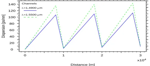
Figure 2 shows, that with the increase of span from 10 Km to 30 Km, dispersion rise. Also, it is observed that dispersion rises when video signal having a wavelength of 1.5500 𝜇m is communicated in comparison to the voice/data signal transmitted at a wavelength of 1.4900 𝜇m.
Fig. 2: Effect of Distance on dispersion
Dispersion Map
x104
Distance [m]
0 1 2 3
D
isp
er
si
on
[p
s/
nm
]
0 20 40 60 80 100 120
140 Channels
=1.4900 m
Fig. 3: Effect of Distance on BER
Figure 3 displays, the relationship between BER and distance. BER is recorded when information is transmitted when error correcting code is applied. It is noted that with the rise in distance, BER also increases. It is noticed that BER is more for the transmission rate of 2.50 Gbps as compared to 1.25 Gbps when information signal is communicated without correcting it with FEC.
Fig. 4: Effect of Distance on BER
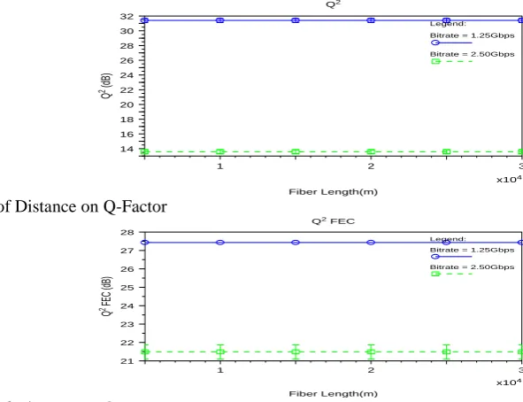
Figure 4 demonstrates the effect of FEC technique on the transmitted information, When FEC is applied to the communicated data signal, BER is reduced at different data rates of 1.25 and 2.50 Gbps. Also, we have observed that with the decline in BER the fiber length are scaled up to 30 Km with acceptable quality of the received signal. Figure 5 gives the effect of distance on quality factor. Q-factor is measured when information is transmitted without correcting the errors with the use of FEC technique. Information is communicated at data rate of 1.5 Gbps and 2.50 Gbps. It is noted that Q-factor reduces with the increase in fiber length from 20 Km to 30 Km. It is observed, that at the data rate of 1.25 Gbps the Q- factor is more in comparison to the bit rate of 2.50 Gbps.
Fig. 5: Effect of Distance on Q-Factor
Fig. 6: Effect of Distance on Q-Factor
Figure 6 depicts the effect on transmitted information when error correcting code FEC is applied. It is noted that Q- factor rises with the rise of separation from 20 Km to 30 Km. It is analyzed that, with the help of FEC technique the quality is enhanced as the system is spanned up to 30 Km.
BER
x104
Fiber Length(m)
1 2 3
BE
R
10-138
10-102
10-75
10-55
10-41
10-30
10-22
10-16
10-12
10-9
10-6
Legend: Bitrate = 1.25Gbps
Bitrate = 2.50Gbps
BER FEC
x104
Fiber Length(m)
1 2 3
BE
R
FE
C
10-100
10-89
10-79
10-70
10-62
10-55
10-49
10-43
10-38
10-33
10-29
Legend: Bitrate = 1.25Gbps
Bitrate = 2.50Gbps
Q2
x104
Fiber Length(m)
1 2 3
Q
2 (d
B)
14 16 18 20 22 24 26 28 30 32
Legend: Bitrate = 1.25Gbps Bitrate = 2.50Gbps
Q2
FEC
x104
Fiber Length(m)
1 2 3
Q
2 FEC
(d
B)
21 22 23 24 25 26 27 28
Legend:
Bitrate = 1.25Gbps
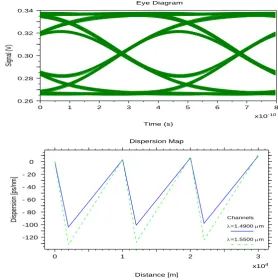
Fig. 7: Eye Diagram
Fig. 8: Relation of Distance with dispersion
The effect of rise in distance on dispersion is depicted in Figure 8. It is visible that with the rise of distance, dispersion grows for the signals communicated at different wavelengths. As demonstrated in figure 9, BER rises when the sepration between OLT and ONU is enhanced. BER observed to be more when the signal transmits at the bit rate of 2.50 Gbps.
Fig. 9: Relationship between BER and distance
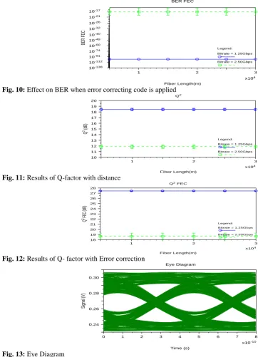
As we observed in figure 10, it is noted that by using the FEC technique, BER is reduced which improves the performance of the system. The system performs better but not so in comparison to the system where post-dispersion compensating fiber is used. Q-factor reduces when the distance is increased. This decrease is more when the signal transmits at the information rate of 2.50 Gbps. The relationship is shown in figure 11. Figure 12 depicts the relationship between distance and q- factor. The result of GEPON model demonstrates that by using the error correction the q-factor of network is enhanced. With FEC mechanism, Q-factor grows even when separation is increased from 20 Km to 30 Km.
Eye Diagram
x10-10
Time (s)
0 1 2 3 4 5 6 7 8
Si
gn
al
(V
)
0.26 0.28 0.30 0.32 0.34
Dispersion Map
x104
Distance [m]
0 1 2 3
D
is
pe
rs
io
n
[p
s/
nm
]
120
-100
-80
-60
-40
-20
-0
Channels
=1.4900 m
=1.5500 m
BER
x104
Fiber Length(m)
1 2 3
BE
R
10-23
10-19
10-16
10-13
10-11
10-9
10-7
10-5
10-4
Legend:
Bitrate = 1.25Gbps
Fig. 10: Effect on BER when error correcting code is applied
Fig. 11: Results of Q-factor with distance
Fig. 12: Results of Q- factor with Error correction
Fig. 13: Eye Diagram
Eye diagram displayed in figure 13, elaborates that by using Pre-dispersion compensation fiber the height and width of the eye is decreased. So, it can be described that the received signal is distorted.
From the table 1, it is observed that dispersion is reduced when post compensation technique is employed. Also, it is noted that data and audio signal encounters less dispersion in comparison with a video signal over a distance of 30 km. Dispersion affects more to a video signal which can be better compensated by using post compensation technique in comparison with a pre compensation technique.
Table 2 and 3, shows the effect of post compensation with and without the use of FEC. Bit error rate (BER) and Q-Factor is noted at a transmission rate of 1.25 Gbps and 2.5 Gbps. The transmission span is taken as 30 Km. It is observed, that the quality factor is 31.46 db when measured for 1.25 Gbps and is 13.6 db for 2.5 Gbps. Quality factor improves for 2.5 Gbps when measured with FEC. BER also improves with the application of FEC.
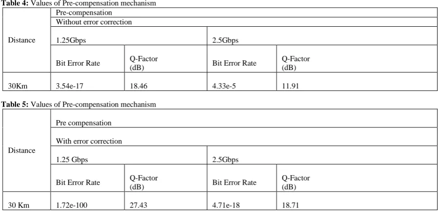
Tables 4 and 5, shows the effect of pre compensation technique for the data rate of 1.25 & 2.5 Gbps. It is noted that bit error rate (BER) is less at 1.25 Gbps and increases when information signal is communicated at a rate of 2.5 Gbps. It further, drops when data is transmitted after applying FEC.
BER FEC
x104
Fiber Length(m)
1 2 3
BE
R
F
EC
10-138
10-112
10-91
10-74
10-60
10-49
10-40
10-32
10-26
10-21
10-17
Legend: Bitrate = 1.25Gbps
Bitrate = 2.50Gbps
Q2
x104
Fiber Length(m)
1 2 3
Q
2 (d
B)
10 11 12 13 14 15 16 17 18 19 20
Legend: Bitrate = 1.25Gbps Bitrate = 2.50Gbps
Q2
FEC
x104
Fiber Length(m)
1 2 3
Q
2 FEC
(d
B)
18 19 20 21 22 23 24 25 26 27 28
Legend:
Bitrate = 1.25Gbps
Bitrate = 2.50Gbps
Eye Diagram
x10-10
Time (s)
0 1 2 3 4 5 6 7 8
Si
gn
al
(V
)
Table 1: Values of Dispersion for 30 Km
Distance
Post-
Compensation Pre-compensation
Dispersion [ps/nm] Dispersion [ps/nm]
Data/Voice Video Data/Voice Video
30 km 8.83 9.30 9.55 9.85
Table 2: Values of Post-compensation mechanism
Distance
Post- compensation
Without error correction
1.25 Gbps 2.5 Gbps
Bit Error Rate Q-Factor
(dB) Bit Error Rate
Q-Factor (dB)
30 km 2.18e-99 31.46 1.07e-6 13.6
Table 3: Values of Post-compensation mechanism
Distance
Post- compensation
With error correction
1.25Gbps 2.5Gbps
Bit Error Rate Q-Factor
(dB) Bit Error Rate
Q-Factor (dB)
30 Km 1.93e-100 27.45 9.38e-33 21.5
Moreover, it is noticed that q factor is reduced with the rise in data rate. Q factor is improved further when information is communicated with FEC. It is deduced from the above discussion that quality of the received information is improved by applying forward error correction. Also, with the rise of transmission rate dispersion grows. Dispersion is better compensated by using post compensation technique. Further, information can be communicated at a high rate which is an essential requirement of optical access systems.
Table 4: Values of Pre-compensation mechanism
Distance
Pre-compensation Without error correction
1.25Gbps 2.5Gbps
Bit Error Rate Q-Factor
(dB) Bit Error Rate
Q-Factor (dB)
30Km 3.54e-17 18.46 4.33e-5 11.91
Table 5: Values of Pre-compensation mechanism
Distance
Pre compensation
With error correction
1.25 Gbps 2.5Gbps
Bit Error Rate Q-Factor
(dB) Bit Error Rate
Q-Factor (dB)
30 Km 1.72e-100 27.43 4.71e-18 18.71
Conclusion:
post-dispersion compensation performs better. Compensating through pre compensation mechanism, it is noted that the height and width of the eye is reduced and the information signal received is deformed. Further, by employing post-dispersion compensation technique, it is noted that height and width of the eye is wide and information received is of good quality. So, we can deduce that the quality of the conveyed multimedia signal is enhanced by the use of dispersion compensation and error correction.
REFERENCES
Abdallah Shami, 2005. QoS control schemes for two-stage ethernet passive optical access networks. IEEE Journal on Selected Areas in Communications, 23(8): 1476-147.
Ahmad, R. Dhaini et al., 2007. Per-stream QoS and admission control in ethernet passive optical networks (EPONs). IEEE Journal of Lightwave Technology, 25(7): 1659-1669.
Chadi, M. Assi et al., 2003. Dynamic bandwidth allocation for quality-of- service over ethernet PONs. IEEE Journal on Selected Areas in Communications, 21(9): 1467-1476.
Chien Aun Chan, 2010. Remote repeater-based EPON with MAC forwarding for long-reach and high-split-ratio passive optical networks. J. Opt. Commn. Netwk. 2: 28-37.
Christophe Peucheret, 2000. Optimization of pre- and post-dispersion compensation schemes for 10-Gbits/s NRZ links using standard and dispersion compensating fibers,” IEEE Photonic Technology Letters, 12(8): 992-994.
Darren P. Shea, 2007 .A 10-Gb/s 1024-way-split 100-km long-reach optical-access network. IEEE Journal of Lightwave Technology, 25(3): 685-693.
Frank J. Effenberger et al., 2010. Standardization trends and prospective views on the next generation of broadband optical access systems. IEEE Journal on Selected Areas in Communications, 28(6): 773-780.
FTTH council, 2008. (Online).http://www.ftthcouncil.org/en/newsroom/2008/09/22/study-shows-fiber-to-the-home-is-is-a-green-technology.
ITU-T.recommendation..984.3,2014. Gigabit-capable passive optical networks (G-PON): Transmission
convergence layer specification.
Md. Shamim Ahsan et al., 2011. Migration to the next generation optical access network. Journal of Networks, 6(1): 18-25.
Monika Gupta et al, 2010. Performance analysis of FTTH at 10 Gb/s by GEPON architecture. International Journal of Computer Science., 7(5): 265-271.
Petar S. Matavulj et al., 2009. Implementation of intra- ONU scheduling for quality of service support in ethernet passive optical networks. IEEE Journal of LightwaveTechnology, 27(18): 4055-4062.
P. Cadro et al., 2001 A Techno-Economic Evaluation of FSAN based ATM PON Network for Business Customers., OHAN/FSAN.