NSX Installation and Upgrade Guide
NSX 6.0 for vSphere
This document supports the version of each product listed and
supports all subsequent versions until the document is
replaced by a new edition. To check for more recent editions
of this document, see
http://www.vmware.com/support/pubs
.
You can find the most up-to-date technical documentation on the VMware Web site at: http://www.vmware.com/support/
The VMware Web site also provides the latest product updates.
If you have comments about this documentation, submit your feedback to: [email protected]
Copyright © 2010 – 2015 VMware, Inc. All rights reserved. Copyright and trademark information.
VMware, Inc.
3401 Hillview Ave. Palo Alto, CA 94304 www.vmware.com
Contents
About this Book 5
1
Overview of NSX 7
NSX Capabilities 8 NSX Components 92
Preparing for Installation 13
System Requirements for NSX 13Ports Required for NSX Communication 14 About VMware Tools on NSX Components 14
3
Installing the NSX Manager 15
Obtain the NSX Manager OVA File 15 Install the NSX Manager Virtual Appliance 15 Log In to the NSX Manager Virtual Appliance 17 Register vCenter Server with NSX Manager 17 Schedule a Backup of NSX Manager Data 184
Installing NSX Components 19
Install and Assign NSX for vSphere License 19 Install Network Virtualization Components 20 Prepare and Enable Clusters for Logical Switches 20 Install NSX Edge 28
Install vShield Endpoint 36 Install Data Security 38 Create an IP Pool 39
5
Extensibility (Integrate Partner Solutions with NSX) 41
Register a Partner Solution Manually 41Install a Partner Service 43
6
Upgrade vShield 5.5 to NSX 6.0.x 45
Upgrade to NSX Manager 45Upgrade to Logical Switches and Install Network Virtualization Components 46 Upgrade to NSX Firewall 48
Upgrade to NSX Edge 49 Upgrade vShield Endpoint 50 Upgrade to NSX Data Security 50 Upgrade Partner Solutions 50
7
Upgrade NSX 6.0 to NSX 6.0.x 51
Upgrade NSX Manager from version 6.0 to 6.0.x 51 Update Clusters 52
Upgrade NSX Edge from 6.0 to 6.0.x 52
8
Uninstalling NSX Components 53
Uninstall an NSX Edge 53Uninstall an NSX Data Security Virtual Machine 53 Uninstall a vShield Endpoint Module 54
Uninstall Network Virtualization Components 54
9
Troubleshooting Installation Issues 55
Unable to Configure Lookup Service 55 Unable to Configure vCenter Server 55Index 57
About this Book
This manual, the NSX Installation and Upgrade Guide, describes how to install and upgrade the VMware®NSX™ system by using the vSphere Web Client. The information includes step-by-step configuration instructions, and suggested best practices.
Intended Audience
This manual is intended for anyone who wants to install or use NSX in a VMware vCenter environment. The information in this manual is written for experienced system administrators who are familiar with virtual machine technology and virtual datacenter operations. This manual assumes familiarity with VMware Infrastructure 5.x, including VMware ESX, vCenter Server, and the vSphere Web Client.
VMware Technical Publications Glossary
VMware Technical Publications provides a glossary of terms that might be unfamiliar to you. For definitions of terms as they are used in VMware technical documentation, go to
http://www.vmware.com/support/pubs.
Document Feedback
VMware welcomes your suggestions for improving our documentation. If you have comments, send your feedback to [email protected].
Technical Support and Education Resources
The following technical support resources are available to you. To access the current version of this book and other books, go to http://www.vmware.com/support/pubs.
Online and Telephone Support
To use online support to submit technical support requests, view your product and contract information, and register your products, go to http://www.vmware.com/support.
Customers with appropriate support contracts should use telephone support for the fastest response on priority 1 issues. Go to
http://www.vmware.com/support/phone_support.html.
Support Offerings To find out how VMware support offerings can help meet your business
needs, go to http://www.vmware.com/support/services.
VMware Professional Services
VMware Education Services courses offer extensive hands-on labs, case study examples, and course materials designed to be used as on-the-job reference tools. Courses are available onsite, in the classroom, and live online. For onsite pilot programs and implementation best practices,
VMware Consulting Services provides offerings to help you assess, plan, build, and manage your virtual environment. To access information about education classes, certification programs, and consulting services, go to http://www.vmware.com/services.
Overview of NSX
1
VMware NSX® is a software networking and security virtualization platform that delivers the operational model of a virtual machine for the network. Virtual networks reproduce the Layer2 - Layer7 network model in software, allowing complex multi-tier network topologies to be created and provisioned
programmatically in seconds. NSX also provides a new model for network security. Security profiles are distributed to and enforced by virtual ports and move with virtual machines.
NSX supports VMware's software-defined data center strategy. By extending the virtualization capabilities of abstraction, pooling and automation across all data center resources and services, the software-defined data center architecture simplifies and speeds the provisioning and management of compute, storage and networking resources through policy-driven automation. By virtualizing the network, NSX delivers a new operational model for networking that breaks through current physical network barriers and enables data center operators to achieve better speed and agility with reduced costs.
NSX includes a library of logical networking services - logical switches, logical routers, logical firewalls, logical load balancers, logical VPN, and distributed security. You can create custom combinations of these services in isolated software-based virtual networks that support existing applications without modification, or deliver unique requirements for new application workloads. Virtual networks are programmatically provisioned and managed independent of networking hardware. This decoupling from hardware introduces agility, speed, and operational efficiency that can transform datacenter operations. Examples of NSX use cases include:
n Data center automation
n Speed up network provisioning
n Simplify service insertion - virtual and physical n Streamline DMZ changes
n Self-Service Enterprise IT
n Rapid application deployment with automated network and service provisioning for private clouds and test/dev environments
n Isolated dev, test, and production environments on the same physical infrastructure n Multi-tenant clouds
n Automate network provisioning for tenants with customization and complete isolation n Maximize hardware sharing across tenants
This chapter includes the following topics: n “NSX Capabilities,” on page 8 n “NSX Components,” on page 9
NSX Capabilities
NSX offers a variety of logical networking services.
Logical Switches
A cloud deployment or a virtual data center has a variety of applications across multiple tenants. These applications and tenants require isolation from each other for security, fault isolation, and avoiding overlapping IP addressing issues. The NSX logical switch creates logical broadcast domains or segments to which an application or tenant virtual machine can be logically wired. This allows for flexibility and speed of deployment while still providing all the characteristics of a physical network's broadcast domains (VLANs) without physical Layer 2 sprawl or spanning tree issues.
A logical switch is distributed and can span arbitrarily large compute clusters. This allows for virtual machine mobility (vMotion) within the datacenter without limitations of the physical Layer 2 (VLAN) boundary. The physical infrastructure does not have to deal with MAC/FIB table limits since the logical switch contains the broadcast domain in software.
Logical Routers
Dynamic routing provides the necessary forwarding information between layer 2 broadcast domains, thereby allowing you to decrease layer 2 broadcast domains and improve network efficiency and scale. NSX extends this intelligence to where the workloads reside for doing East-West routing. This allows more direct virtual machine to virtual machine communication without the costly or timely need to extend hops. At the same time, NSX also provides North-South connectivity, thereby enabling tenants to access public networks.
Logical Firewall
Logical Firewall provides security mechanisms for dynamic virtual data centers. The Distributed Firewall component of Logical Firewall allows you to segment virtual datacenter entities like virtual machines based on VM names and attributes, user identity, vCenter objects like datacenters, and hosts as well as traditional networking attributes like IP addresses, VLANs, etc. The Edge Firewall component helps you achieve key perimeter security needs such as building DMZs based on IP/VLAN constructs, tenant to tenant isolation in multi-tenant virtual data centers, Network Address Translation (NAT), partner (extranet) VPNs, and User based SSL VPNs.
The Flow Monitoring feature displays network activity between virtual machines at the application protocol level. You can use this information to audit network traffic, define and refine firewall policies, and identify threats to your network.
Logical Virtual Private Networks (VPN)s
SSL VPN-Plus allows remote users to access private corporate applications. IPSec VPN offers site-to-site connectivity between an NSX Edge instance and remote sites. L2 VPN allows you to extend your datacenter by allowing virtual machines to retain network connectivity across geographical boundaries.
Logical Load Balancer
The NSX Edge load balancer enables network traffic to follow multiple paths to a specific destination. It distributes incoming service requests evenly among multiple servers in such a way that the load distribution is transparent to users. Load balancing thus helps in achieving optimal resource utilization, maximizing throughput, minimizing response time, and avoiding overload. NSX Edge provides load balancing up to Layer 7.
Service Composer
Service Composer helps you provision and assign network and security services to applications in a virtual infrastructure. You map these services to a security group, and the services are applied to the virtual machines in the security group.
Data Security provides visibility into sensitive data stored within your organization's virtualized and cloud environments. Based on the violations reported by NSX Data Security, you can ensure that sensitive data is adequately protected and assess compliance with regulations around the world.
NSX Extensibility
VMware partners can integrate their solutions with the NSX platform, which enables customers to have an integrated experience across VMware products and partner solutions. Data center operators can provision complex, multi-tier virtual networks in seconds, independent of the underlying network topology or components.
NSX Components
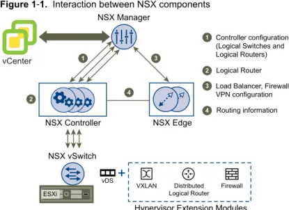
This section describes NSX components. NSX can be configured through the vSphere Web Client, a command line interface (CLI), and REST API.
can be
Figure 1‑1. Interaction between NSX components
ESXi
vDS
VXLAN Distributed Logical Router
Firewall Hypervisor Extension Modules
vCenter
NSX Manager
NSX Controller NSX Edge
1
2
3
4
Controller configuration (Logical Switches and Logical Routers) Logical Router Load Balancer, Firewall, VPN configuration 1
2 3
4 Routing information
NSX vSwitch
NSX Manager
The NSX Manager is the centralized network management component of NSX, and is installed as a virtual appliance on any ESX™ host in your vCenter Server environment. It provides an aggregated system view. One NSX Manager maps to a single vCenter Server environment and multiple NSX Edge, vShield Endpoint, and NSX Data Security instances.
NSX vSwitch
NSX vSwitch is the software that operates in server hypervisors to form a software abstraction layer between servers and the physical network.
As the demands on datacenters continue to grow and accelerate, requirements related to speed and access to the data itself continue to grow as well. In most infrastructures, virtual machine access and mobility usually depend on physical networking infrastructure and the physical networking environments they reside in. This can force virtual workloads into less than ideal environments due to potential layer 2 or layer 3 boundaries, such as being tied to specific VLANs.
NSX vSwitch allows you to place these virtual workloads on any available infrastructure in the datacenter regardless of the underlying physical network infrastructure. This not only allows increased flexibility and mobility, but increased availability and resilience.
NSX Controller
NSX controller is an advanced distributed state management system that controls virtual networks and overlay transport tunnels.
NSX controller is the central control point for all logical switches within a network and maintains
information of all virtual machines, hosts, logical switches, and VXLANs. The controller supports two new logical switch control plane modes, Unicast and Hybrid. These modes decouple NSX from the physical network. VXLANs no longer require the physical network to support multicast in order to handle the Broadcast, Unknown unicast, and Multicast (BUM) traffic within a logical switch. The unicast mode replicates all the BUM traffic locally on the host and requires no physical network configuration. In the hybrid mode, some of the BUM traffic replication is offloaded to the first hop physical switch to achieve better performance.
NSX Edge
NSX Edge provides network edge security and gateway services to isolate a virtualized network. You can install an NSX Edge either as a logical (distributed) router or as a services gateway.
The NSX Edge logical (distributed) router provides East-West distributed routing with tenant IP address space and data path isolation. Virtual machines or workloads that reside on the same host on different subnets can communicate with one another without having to traverse a traditional routing interface. The NSX Edge gateway connects isolated, stub networks to shared (uplink) networks by providing common gateway services such as DHCP, VPN, NAT, dynamic routing, and Load Balancing. Common deployments of NSX Edge include in the DMZ, VPN Extranets, and multi-tenant Cloud environments where the NSX Edge creates virtual boundaries for each tenant.
NSX Edge Services
Dynamic Routing Provides the necessary forwarding information between layer 2 broadcast
domains, thereby allowing you to decrease layer 2 broadcast domains and improve network efficiency and scale. NSX extends this intelligence to where the workloads reside for doing East-West routing. This allows more direct virtual machine to virtual machine communication without the costly or timely need to extend hops. At the same time, NSX also provides North-South connectivity, thereby enabling tenants to access public networks.
Firewall Supported rules include IP 5-tuple configuration with IP and port ranges for
stateful inspection for all protocols.
Network Address Translation
Separate controls for Source and Destination IP addresses, as well as port translation.
Dynamic Host
Configuration Protocol (DHCP)
Configuration of IP pools, gateways, DNS servers, and search domains.
Site-to-Site Virtual Private Network (VPN)
Uses standardized IPsec protocol settings to interoperate with all major VPN vendors.
L2 VPN Provides the ability to stretch your L2 network.
SSL VPN-Plus SSL VPN-Plus enables remote users to connect securely to private networks behind a NSX Edge gateway.
Load Balancing Simple and dynamically configurable virtual IP addresses and server groups.
High Availability High availability ensures an active NSX Edge on the network in case the
primary NSX Edge virtual machine is unavailable. NSX Edge supports syslog export for all services to remote servers.
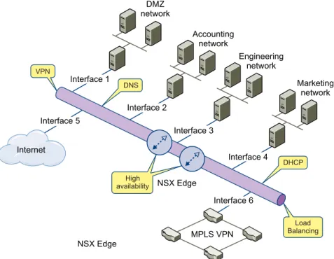
Figure 1‑2. Multi-Interface Edge
NSX Edge MPLS VPN Internet Interface 1 Interface 3 Interface 2 Interface 4 Interface 6 Interface 5 DMZ network Accounting network Marketing network Engineering network VPN Load Balancing DNS DHCP availabilityHigh NSX Edge
Distributed Firewall
NSX Distributed Firewall is a hypervisor kernel-embedded firewall that provides visibility and control for virtualized workloads and networks. You can create access control policies based on VMware vCenter objects like datacenters and clusters, virtual machine names and tags, network constructs such as
IP/VLAN/VXLAN addresses, as well as user group identity from Active Directory. Consistent access control policy is now enforced when a virtual machine gets vMotioned across physical hosts without the need to rewrite firewall rules. Since Distributed Firewall is hypervisor-embedded, it delivers close to line rate throughput to enable higher workload consolidation on physical servers. The distributed nature of the firewall provides a scale-out architecture that automatically extends firewall capacity when additional hosts are added to a datacenter.
Preparing for Installation
2
This section describes the system requirements for NSX as well as the ports that must be open. This chapter includes the following topics:
n “System Requirements for NSX,” on page 13
n “Ports Required for NSX Communication,” on page 14 n “About VMware Tools on NSX Components,” on page 14
System Requirements for NSX
Before you install NSX in your vCenter Server environment, consider your network configuration and resources. You can install one NSX Manager per vCenter Server, one vShield Endpoint per ESX™ host, and multiple NSX Edge instances per datacenter.
Hardware
Table 2‑1. Hardware Requirements
Component Minimum
Memory n NSX Manager: 12 GB
n NSX Edge Compact: 512 MB, Large: 1 GB, X-Large: 8 GB, and Quad Large: 1 GB n vShield Endpoint: 1 GB
n NSX Data Security: 512 MB
Disk Space n NSX Manager: 60 GB
n NSX Edge Compact, Large, and Quad Large: 512 MB, X-Large: 4.5 GB (with 4
GB swap)
n vShield Endpoint: 4GB
n NSX Data Security: 6GB per ESX host
vCPU n NSX Manager: 4
n NSX Edge Compact: 1, Large:2, Quad Large: 4, and X-Large:6 n vShield Endpoint: 2
n NSX Data Security: 1
Software
For the latest interoperability information, see the Product Interoperability Matrix at http://partnerweb.vmware.com/comp_guide/sim/interop_matrix.php.
These are the minimum required versions of VMware products. n VMware vCenter Server 5.5 or later
n VMware ESX 5.0 or later for each server n VMware Tools
For vShield Endpoint and NSX Data Security, you must upgrade your virtual machines to hardware version 7 or 8 and install VMware Tools 8.6.0 released with ESXi 5.0 Patch 3. For more information, see “Install VMware Tools on the Guest Virtual Machines,” on page 37.
Client and User Access
n PC with the VMware vSphere Web Client
n If you added ESX hosts by name to the vSphere inventory, ensure that DNS servers have been configured on the NSX Manager and name resolution is working. Otherwise, NSX Manager cannot resolve the IP addresses.
n Permissions to add and power on virtual machines
n Access to the datastore where you store virtual machine files, and the account permissions to copy files to that datastore
n Enable cookies on your Web browser to access the NSX Manager user interface
n From NSX Manager, port 443 accessible from the ESX host, the vCenter Server, and the NSX appliances to be deployed. This port is required to download the OVF file on the ESX host for deployment. n Connect to the NSX Manager using one of the following supported Web browsers:
n Microsoft Internet Explorer 8, 9 (64-bit only), and 10.
n Mozilla Firefox: the latest browser version, and the one previous version at the time the NSX 6.0 is produced.
n Google Chrome: the latest browser version, and the one previous version at the time the NSX 6.0 is produced.
Ports Required for NSX Communication
The following ports must be open on NSX Manager.Table 2‑2.
Port Required for
443/TCP n Downloading the OVA file on the ESX host for deployment n Using REST APIs
n Using the NSX Manager user interface
80/TCP n Initiating connection to the vSphere SDK
n Messaging between NSX Manager and NSX host modules
1234/TCP Communication between ESX Host and NSX Controller Clusters 5671 Rabbit MQ (messaging bus technology)
22/TCP Console access (SSH) to CLI. By default, this port is closed.
If the hosts in your clusters were upgraded from vCenter Server version 5.0 to 5.5, you must open ports 80 and 443 on those hosts for Guest Introspection installation to be successful.
About VMware Tools on NSX Components
Each NSX virtual appliance includes VMware Tools. Do not upgrade or uninstall the version of VMware Tools included with a NSX virtual appliance.
Installing the NSX Manager
3
The NSX Manager is the centralized management component of NSX, and runs as a virtual appliance on an ESX host.
VMware recommends that you install NSX Manager on a dedicated management cluster separate from the cluster(s) that NSX Manager manages. Each NSX Manager manages a single vCenter Server environment. The NSX Manager requires connectivity to the vCenter Server, ESXi host, and NSX Edge instances, vShield Endpoint module, and NSX Data Security virtual machine. NSX components can communicate over routed connections as well as different LANs.
The NSX Manager should be run on an ESX host that is not affected by downtime, such as frequent reboots or maintenance mode operations. You can use HA or DRS to increase the resilience of the NSX Manager. If the ESX host on which the NSX Manager resides is expected to require downtime, vMotion the NSX Manager virtual appliance to another ESX host. Thus, more than one ESX host is recommended. Ensure that the following ports are open:
n Port 443/TCP from, to, and among the ESX host, the vCenter Server, and NSX Data Security n 443/TCP from the REST client to NSX Manager for using REST API calls
n 80/TCP and 443/TCP for using the NSX Manager user interface and initiating connection to the vSphere SDK
This chapter includes the following topics:
n “Obtain the NSX Manager OVA File,” on page 15 n “Install the NSX Manager Virtual Appliance,” on page 15 n “Log In to the NSX Manager Virtual Appliance,” on page 17 n “Register vCenter Server with NSX Manager,” on page 17 n “Schedule a Backup of NSX Manager Data,” on page 18
Obtain the NSX Manager OVA File
The NSX Manager virtual machine is packaged as an Open Virtualization Appliance (OVA) file, which allows you to use the vSphere Web Client to import the NSX Manager into the datastore and virtual machine inventory.
Install the NSX Manager Virtual Appliance
You can install the NSX Manager virtual machine on an ESX host in a cluster configured with DRS. You can install the NSX Manager in a different vCenter than the one that the NSX Manager will be interoperating with. A single NSX Manager serves a single vCenter Server environment.
The NSX Manager virtual machine installation includes VMware Tools. Do not attempt to upgrade or install VMware Tools on the NSX Manager.
Prerequisites
You must have been assigned the Enterprise Administrator or NSX Administrator role.
Procedure
1 Log in to the vSphere Web Client. 2 Select vCenter and then select Hosts.
The NSX Manager management interface, vCenter Server, and ESXi hosts must be reachable by all future NSX Edge and vShield Endpoint instances.
3 Right-click the host where you want to install NSX Manager and select Deploy OVF Template. It may take a few seconds for the Deploy OVF Template option to be displayed.
4 If this is the first time that you are deploying an OVF file, follow these steps. a Download the VMware Client Integration Plug-in.
b Close all browser windows.
c Install the VMware Client Integration Plug-in.
d Log in to the vSphere Web Client again and navigate to the host where you were installing NSX Manager.
e Repeat Step 3.
5 Enter the URL to download and install the OVF file from the internet or click Browse to locate the folder on your computer that contains the NSX Manager OVA file and click Next.
6 Review the OVF template details and click Next.
7 Click Accept to accept the VMware license agreements and click Next.
8 Edit the name (if required) and select the location for the NSX Manager that you are installing. 9 Click Next.
10 Select the location to run the template.
11 On the Select storage page, select the storage for the NSX Manager and click Next.
12 On the Setup networks page, confirm that the NSX Manager adapter has been mapped to the correct host network and click Next.
13 Specify whether you want to configure IPv4 only, IPv6 only, or dual-stack network configuration. If you are configuring a dual-stack network, the host name of the NSX Manager will be used by other entities. Hence, the NSX Manager host name must be mapped to the right IP address in the DNS servers used in that network.
14 On the Customized template page, specify the following values. a Type and re-type the root user password.
b Type and re-type the CLI password.
c Type and re-type the CLI privilege mode password.
d Click Network Properties and type the hostname for the NSX Manager virtual machine. e Type the network IPv4 address, netmask, and default gateway.
g Click DNS and type the IP addresses for DNS servers and domain search list.
h Click Services Configuration and type the NTP server lis for the NSX Manager virtual machine. i To enable SSH, select the Enable SSH checkbox.
j Click Next.
15 On the Ready to complete page, review the NSX Manager settings and click Finish. The NSX Manager is installed as a virtual machine in your inventory.
16 Power on the NSX Manager virtual machine.
Log In to the NSX Manager Virtual Appliance
After you have installed and configured the NSX Manager virtual machine, log in to the NSX Manager virtual appliance to review the settings specified during installation.
Procedure
1 Open a Web browser window and type the IP address assigned to the NSX Manager. For example,
https://11.111.11.11.
The NSX Manager user interface opens in a web browser window using SSL. 2 Accept the security certificate.
NOTE You can use an SSL certificate for authentication. Refer to the NSX Administration Guide.
The NSX Manager login screen appears.
3 Log in to the NSX Manager virtual appliance by using the user name admin and the password you set
during installation. If you had not set a password during installation, type default as the password.
4 Click Log In.
Register vCenter Server with NSX Manager
You must login to the NSX Manager virtual appliance to register a vCenter Server and review the settings specified during installation.
Prerequisites
n You must have a vCenter Server user account with administrative access to synchronize NSX Manager with the vCenter Server . If your vCenter password has non-Ascii characters, you must change it before synchronizing the NSX Manager with the vCenter Server.
n To use SSO on NSX Manager, you must have vCenter Server 5.5 or later and single sign on service must be installed on the vCenter Server.
Procedure
1 Log in to the NSX Manager virtual appliance.
2 Under Appliance Management, click Manage Appliance Settings.
3 From the left panel, select NSX Management Service and click Configure next to vCenter Server. 4 Type the IP address of the vCenter Server.
5 Type the vCenter Server user name and password. 6 Click OK.
Confirm that the vCenter Server status is Connected.
What to do next
Login to the vSphere Web Client and click the Networking & Security tab. You can now install and configure NSX components.
VMware recommends that you schedule a backup of NSX Manager data right after installing NSX Manager. See NSX Administration Guide.
Schedule a Backup of NSX Manager Data
It is recommended that you schedule a backup right after you install NSX Manager.
Procedure
1 Log in to the NSX Manager Virtual Appliance.
2 Under Appliance Management, click Backups & Restore.
3 To specify the backup location, click Change next to FTP Server Settings. a Type the IP address or host name of the backup system.
b From the Transfer Protocol drop-down menu, select either SFTP or FTP, based on what the destination supports.
c Edit the default port if required.
d Type the user name and password required to login to the backup system.
e In the Backup Directory field, type the absolute path where backups will be stored. f Type a text string in Filename Prefix.
This text is prepended to each backup filename for easy recognition on the backup system. For example, if you type ppdb, the resulting backup is named as ppdbHH_MM_SS_DayDDMonYYYY.
g Type the pass phrase to secure the backup. h Click OK.
4 To specify schedule details, click Change next to Scheduling.
a From the Backup Frequency drop-down menu, select Hourly, Daily, or Weekly. The Day of Week, Hour of Day, and Minute drop-down menus are disabled based on the selected frequency. For example, if you select Daily, the Day of Week drop-down menu is disabled as this field is not applicable to a daily frequency.
b For a weekly backup, select the day of the week and hour that the data should be backed up. c Select the minute at which the backup should begin and click Schedule.
Installing NSX Components
4
After the NSX Manager is installed, you can obtain licenses to activate the NSX Endpoint, NSX Edge, and NSX Data Security components. The NSX Manager OVA package includes the drivers and files required to install these add-on components.
NSX virtual appliances include VMware Tools. Do not attempt to alter or upgrade the VMware Tools software on an NSX virtual appliance.
This chapter includes the following topics:
n “Install and Assign NSX for vSphere License,” on page 19 n “Install Network Virtualization Components,” on page 20 n “Prepare and Enable Clusters for Logical Switches,” on page 20 n “Install NSX Edge,” on page 28
n “Install vShield Endpoint,” on page 36 n “Install Data Security,” on page 38 n “Create an IP Pool,” on page 39
Install and Assign NSX for vSphere License
You can install and assign an NSX for vSphere license after NSX Manager installation is complete by using the vSphere Web Client.
Before purchasing and activating an NSX for vSphere license, you can install and run the software in evaluation mode. When run in evaluation mode, intended for demonstration and evaluation purposes, NSX components are completely operational immediately after installation, do not require any licensing
configuration, and provide full functionality for 60 days from the time you first activate them.
Procedure
1 Log in to the vSphere Web Client.
2 Click Administration and then click Licenses. 3 Click the Solutions tab.
4 From the drop-down menu at the top, select Assign a new license key. 5 Type the license key and an optional label for the new key.
6 Click Decode.
Decode the license key to verify that it is in the correct format, and that it has enough capacity to license the assets.
7 Click OK.
What to do next
Obtain and install an NSX for vSphere license within the evaluation period.
Install Network Virtualization Components
As the demands on datacenters continue to grow and accelerate, requirements related to speed and access to the data itself continue to grow as well. In most infrastructures, virtual machine access and mobility usually depend on physical networking infrastructure and the physical networking environments they reside in. This can force virtual workloads into less than ideal environments due to potential layer 2 or layer 3 boundaries, such as being tied to specific VLAN's.
Network virtualization allows you to place these virtual workloads on any available infrastructure in the datacenter regardless of the underlying physical network infrastructure. This not only allows increased flexibility and mobility, but increased availability and resilience.
You install the network infrastructure components in your virtual environment on a per-cluster level for each vCenter server, which deploys the required software on all hosts in the cluster. When a new host is added to this cluster, the required software is automatically installed on the newly added host. After the network infrastructure is installed on a cluster, Logical Firewall is enabled on that cluster.
Procedure
1 Log in to the vSphere Web Client.
2 Click Networking & Security and then click Installation. 3 Click the Host Preparation tab.
4 For each cluster, select Install in the Installation Status column.
5 Monitor the installation until the Installation Status column displays a green check mark. If the Installation Status column displays a red warning icon and says Not Ready, click Resolve. Clicking Resolve might result in a reboot of the host. If the installation is still not successful, click the warning icon. All errors are displayed. Take the required action and click Resolve again.
When the installation is complete, the Installation Status column displays 6.0 and the Firewall column displays Enabled. Both columns have a green check mark as well.
Prepare and Enable Clusters for Logical Switches
A logical switch creates logical broadcast domains or segments to which an application or tenant virtual machine can be logically wired. This allows for flexibility and speed of deployment while still providing all the characteristics of a physical network's broadcast domains (VLANs) without physical Layer 2 sprawl or spanning tree issues. Configuring logical switches is a multi-step process. You must follow these steps in order to complete logical switch configuration.
Prerequisites
Verify the following.
n You have the Super Administrator or Enterprise Administrator role permission to configure and manage logical switches.
n Network virtualization components are installed on the clusters that are to be part of the logical switch. See
n You have the minimum required software versions.
n Managed IP address is set for each vCenter server in the vCenter Server Runtime Settings. See vCenter Server and Host Management.
n DHCP is available on VXLAN transport VLANs if you are using DHCP for IP assignment for VMKNics n A consistent distributed virtual switch type (vendor etc.) and version is being used across a given
transport zone. Inconsistent switch types can lead to undefined behavior in your logical switch. n 5- tuple hash distribution should be enabled for Link Aggregation Control Protocol (LACP).
Set Up the Control Plane
The controller cluster is the control plane component responsible for managing the switching and routing modules in the hypervisors. It consists of controller nodes to manage specific logical switches. Using a controller cluster to manage VXLAN-based logical switches eliminates the need for multicast support from the physical network infrastructure. You don’t have to provision multicast group IP addresses, and you also don’t need to enable PIM routing or IGMP snooping features on physical switches or routers. Selecting the
Unicast check box while creating the logical switch enables this mode of VXLAN operation.
VMware recommends that you add three controllers for scale and redundancy.
Procedure
1 On the Installation tab, ensure that the Management tab is selected. 2 In the NSX Controller nodes section, click the Add Node ( ) icon.
3 In the Add Controller dialog box, select the datacenter on which you are adding the node. 4 Select the cluster or resource pool where the controller is to be deployed.
5 Select the datastore and host.
6 Select the logical switch, portgroup, or distributed portgroup to which the node is to be connected. The network that the controller is connected to is the management port group on the Distributed Virtual Switch that spans the environment.
7 Select the IP pool from which IP addresses are to be assigned to the node.
NOTE The IP address of the controller must be reachable from the NSX Manager and the management
network of the vSphere hosts communicating with the controller. 8 Type and re-type a password for the controller.
The password must be 8 characters and must follow 3 of the following 4 rules: n At least one upper case letter
n At least one lower case letter n At last one number
n At least one special character 9 Click OK.
When deployed, the controller has a Normal status and displays a green check mark. The NSX controller can now control the traffic flow through your logical switch.
What to do next
Deploy two additional controllers to ensure a greater level of resiliency. Three is the recommended number by VMware. During this period, do not add or modify logical switches or distributed routing in your environment.
If you need to delete a controller, first stop using the logical router or logical switch based on this controller before deleting it.
Assign Segment ID Pool and Multicast Address Range to NSX Manager
You must specify a segment ID pool for each NSX Manager to isolate your network traffic. If an NSX controller is not deployed in your environment, you must add a multicast address range to spread traffic across your network and avoid overloading a single multicast address.The Segment ID Pool specifies a range of VXLAN Network Identifiers (VNIs) for use when building Logical Network segments.
Procedure
1 On the Installation tab, click Logical Network Preparation and then click Segment ID. 2
Click the Edit ( ) icon
3 Type a range for segment IDs. For example, 5000-5200.
The segment ID range determines the maximum number of logical switches that can be created in your infrastructure.
4 If you do not have a deployed NSX controller in your environment, select Enable multicast addressing and type an address range. For example, 239.1.1.10-239.1.1.20.
NOTE You must specify a multicast address range for VMware ESX 5.1 hosts or when using the hybrid
mode. 5 Click OK.
Configure VXLAN Transport Parameters
The VXLAN network is used for Layer 2 Logical Switching across hosts. You configure VXLAN on a per-cluster basis, where you map each per-cluster that is to participate in a logical network to a vDS. When you map a cluster to a switch, each host in that cluster is enabled for logical switches. The settings chosen here will be used in creating the VMkernel interface.
Prerequisites
n All hosts in the cluster must be connected to a vDS. n Network virtualization components must be installed.
Procedure
1 Ensure that you are on the Installation > Host Preparation tab.
2 For the cluster on which you want to configure VXLAN, click Configure in the VXLAN column. 3 In the Configuring VXLAN networking dialog box, select the switch to which you want to map the
cluster.
5 Type the Maximum Transmission Units (MTU) for the virtual distributed switch.
MTU is the maximum amount of data that can be transmitted in one packet before it is divided into smaller packets. VXLAN traffic frames are slightly larger in size because of encapsulation, so the MTU for each switch must be set to 1550 or higher.
6 In VMKNic IP Addressing, specify the IP pool to be used for the Management and Edge cluster.
Select To
Use DHCP Assign an IP address to the VXLAN VTEPs through Dynamic Host Configuration Protocol (DHCP).
Use IP pool Assign a static IP address to the VXLAN VTEPs from the selected IP pool,
or create a new IP pool.
7 If you selected Use IP Pool, select an IP pool.
8 Select the VMKNic Teaming Policy for the vSwitch. The NIC teaming policy determines the load balancing and failover settings of the virtual switch.
It is important to choose the right teaming policy to avoid packet loss. See “Teaming Policy for Virtual Distributed Switches,” on page 23.
9 Edit the VTEP value, if required.
VTEP (VXLAN Tunnel End Points) is the number of dvUplinks on the switch, which load balances traffic between multiple PNICs. VMware recommends that you do not edit the default VTEP value. This field is disabled if the teaming policy you selected does not require multiple VTEPs (ether channel, failover, LACPv1, or LACPv2).
10 Click OK.
Teaming Policy for Virtual Distributed Switches
You should choose a teaming policy for VXLAN transport based on the topology of your physical switches. It is recommended that you do not mix teaming policies for different portgroups on a vSphere Distributed Switch. If uplinks are shared in these different teaming policies, then traffic will be interrupted. For a Logical Distributed Router, mixed teaming policies may result in routing problems. As a best practice - if you want to use IP hash based teaming (Ether channel, LACPv1, or LACPv2), use all uplinks on the vSphere Distributed Switch for the team and do not have portgroups on that vSphere Distributed Switch with different teaming policies.
For certain teaming modes, VMware software creates multiple VTEPs to load balance traffic among the physical vNICs.
For information on teaming mode descriptions, refer to the VMware vSphere documentation.
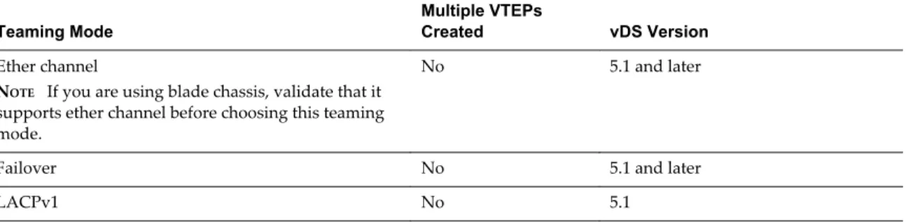
Table 4‑1. Teaming Policy table
Teaming Mode
Multiple VTEPs
Created vDS Version
Ether channel
NOTE If you are using blade chassis, validate that it supports ether channel before choosing this teaming mode.
No 5.1 and later
Failover No 5.1 and later
LACPv1 No 5.1
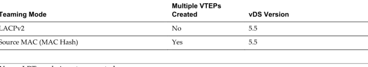
Table 4‑1. Teaming Policy table (Continued)
Teaming Mode
Multiple VTEPs
Created vDS Version
LACPv2 No 5.5
Source MAC (MAC Hash) Yes 5.5
NOTE LBT mode is not supported.
Logical Distributed Routers have the following teaming policy restrictions:
n Source MAC and Source Port teaming policy will work with one VTEP and one active uplink. You can have multiple uplinks with fail-over policy where the other uplinks are in standby state.
Plain VXLAN switching (without Logical Distributed Router) will work with multiple VTEPs and multiple uplinks.
n Static Lag and LACP is supported with one VTEP and multiple uplinks.
Working with Transport Zones
A transport zone is the compute diameter defined by a set of vCenter clusters.
Add a Transport Zone
Procedure1 Log in to the vSphere Web Client.
2 Click Networking & Security and then click Installation.
3 Click Logical Network Preparation and then click Transport Zones. 4 Click the New Transport Zone icon.
5 In the New Transport Zone dialog box, type a name and description for the transport zone.
6 Depending on whether you have a controller node in your environment, or you want to use multicast addresses, select the control plane mode.
n Multicast: Multicast IP addresses on physical network is used for the control plane. This mode is recommended only when you are upgrading from older VXLAN deployments. Requires PIM/IGMP on physical network.
n Unicast : The control plane is handled by an NSX controller. All unicast traffic leverages headend replication. No multicast IP addresses or special network configuration is required.
n Hybrid : The optimized unicast mode. Offloads local traffic replication to physical network (L2 multicast). This requires IGMP snooping on the first-hop switch, but does not require PIM. First-hop switch handles traffic replication for the subnet.
7 Select the clusters to be added to the transport zone. 8 Click OK.
View and Edit a Transport Zone
You can view the logical networks in a selected transport zone, the clusters in, and the control plane mode for that transport zone.
Procedure
1 Log in to the vSphere Web Client.
2 Click Networking & Security and then click Installation.
3 Click Logical Network Preparation and then click Transport Zones. 4 Double-click a transport zone.
The Summary tab displays the name and description of the transport zone as well as the number of logical switches associated with it. Transport Zone Details displays the clusters in the transport zone. 5 Click the Edit Settings icon in the Transport Zone Details section to edit the name, description, or
control plane mode of the transport zone.
If you change the transport zone control plane mode, select Migrate existing Logical Switches to the
new control plane mode to change the control plane more for existing logical switches linked to this
transport zone. If you do not select this check box, only the logical switches linked to this transport zone after the edit is done will have the new control plane mode.
6 Click OK.
Add a Transport Zone Procedure
1 Log in to the vSphere Web Client.
2 Click Networking & Security and then click Installation.
3 Click Logical Network Preparation and then click Transport Zones. 4 Click the New Transport Zone icon.
5 In the New Transport Zone dialog box, type a name and description for the transport zone.
6 Depending on whether you have a controller node in your environment, or you want to use multicast addresses, select the control plane mode.
n Multicast: Multicast IP addresses on physical network is used for the control plane. This mode is recommended only when you are upgrading from older VXLAN deployments. Requires PIM/IGMP on physical network.
n Unicast : The control plane is handled by an NSX controller. All unicast traffic leverages headend replication. No multicast IP addresses or special network configuration is required.
n Hybrid : The optimized unicast mode. Offloads local traffic replication to physical network (L2 multicast). This requires IGMP snooping on the first-hop switch, but does not require PIM. First-hop switch handles traffic replication for the subnet.
7 Select the clusters to be added to the transport zone. 8 Click OK.
Expand a Transport Zone
You can add clusters to a transport zone, which stretches all existing transport zones to become available on the newly added clusters.
Prerequisites
The clusters you add to a transport zone have the network infrastructure installed and are configured for VXLAN. See the NSX Installation and Upgrade Guide.
Procedure
1 Log in to the vSphere Web Client.
2 Click Networking & Security and then click Installation.
3 Click Logical Network Preparation and then click Transport Zones. 4 Click a transport zone.
5
In Transport Zones Details, click the Add Cluster ( ) icon. 6 Select the clusters you want to add to the transport zone. 7 Click OK.
Add a Transport Zone Procedure
1 Log in to the vSphere Web Client.
2 Click Networking & Security and then click Installation.
3 Click Logical Network Preparation and then click Transport Zones. 4 Click the New Transport Zone icon.
5 In the New Transport Zone dialog box, type a name and description for the transport zone.
6 Depending on whether you have a controller node in your environment, or you want to use multicast addresses, select the control plane mode.
n Multicast: Multicast IP addresses on physical network is used for the control plane. This mode is recommended only when you are upgrading from older VXLAN deployments. Requires PIM/IGMP on physical network.
n Unicast : The control plane is handled by an NSX controller. All unicast traffic leverages headend replication. No multicast IP addresses or special network configuration is required.
n Hybrid : The optimized unicast mode. Offloads local traffic replication to physical network (L2 multicast). This requires IGMP snooping on the first-hop switch, but does not require PIM. First-hop switch handles traffic replication for the subnet.
7 Select the clusters to be added to the transport zone. 8 Click OK.
Contract a Transport Zone
You can remove clusters from a transport zone. Existing transport zones may be shrunk to accommodate the contracted scope.
Procedure
1 Log in to the vSphere Web Client.
2 Click Networking & Security and then click Installation.
3 Click Logical Network Preparation and then click Transport Zones. 4 Double-click a transport zone.
5
In Transport Zones Details, click the Remove Clusters ( ) icon. 6 Select the clusters you want to remove.
7 Click OK.
Add a Transport Zone Procedure
1 Log in to the vSphere Web Client.
2 Click Networking & Security and then click Installation.
3 Click Logical Network Preparation and then click Transport Zones. 4 Click the New Transport Zone icon.
5 In the New Transport Zone dialog box, type a name and description for the transport zone.
6 Depending on whether you have a controller node in your environment, or you want to use multicast addresses, select the control plane mode.
n Multicast: Multicast IP addresses on physical network is used for the control plane. This mode is recommended only when you are upgrading from older VXLAN deployments. Requires PIM/IGMP on physical network.
n Unicast : The control plane is handled by an NSX controller. All unicast traffic leverages headend replication. No multicast IP addresses or special network configuration is required.
n Hybrid : The optimized unicast mode. Offloads local traffic replication to physical network (L2 multicast). This requires IGMP snooping on the first-hop switch, but does not require PIM. First-hop switch handles traffic replication for the subnet.
7 Select the clusters to be added to the transport zone. 8 Click OK.
Install NSX Edge
You can install NSX Edge as a services gateway or as a logical router.
NSX Edge Services Gateway
The services gateway gives you access to all NSX Edge services such as firewall, NAT, DHCP, VPN, load balancing, and high availability. You can install multiple NSX Edge services gateway virtual appliances in a datacenter. Each NSX Edge virtual appliance can have a total of ten uplink and internal network interfaces. The internal interfaces connect to secured port groups and act as the gateway for all protected virtual machines in the port group. The subnet assigned to the internal interface can be a publicly routed IP space or a NATed/routed RFC 1918 private space. Firewall rules and other NSX Edge services are enforced on traffic between network interfaces.
Uplink interfaces of NSX Edge connect to uplink port groups that have access to a shared corporate network or a service that provides access layer networking. Multiple external IP addresses can be configured for load balancer, site-to-site VPN, and NAT services.
Logical Router
The NSX Edge logical router provides East-West distributed routing with tenant IP address space and data path isolation. Virtual machines or workloads that reside on the same host on different subnets can communicate with one another without having to traverse a traditional routing interface.
A logical router can have eight uplink interfaces and up to a thousand internal interfaces.
Install an NSX Edge Services Gateway
You can install multiple NSX Edge services gateway virtual appliances in a data center. Each NSX Edge virtual appliance can have a total of ten uplink and internal network interfaces. The internal interfaces connect to secured port groups and act as the gateway for all protected virtual machines in the port group. The subnet assigned to the internal interface can be a publicly routed IP space or a NATed/routed RFC 1918 private space. Firewall rules and other NSX Edge services are enforced on traffic between interfaces. Uplink interfaces of NSX Edge connect to uplink port groups that have access to a shared corporate network or a service that provides access layer networking.
Multiple external IP addresses can be configured for load balancer, site-to-site VPN, and NAT services. Overlapping IP addresses are not allowed for internal interfaces, and overlapping subnets are not allowed for internal and uplink interfaces.
Open the Add Edge Wizard
Open the Add Edge wizard to install and configure an NSX Edge instance.
Procedure
1 Log in to the vSphere Web Client.
2 Click Networking & Security and then click NSX Edges. 3 Click the Add ( ) icon.
4 In the Add Edge Gateway wizard, select Edge Services Gateway .
6 Type a name for the NSX Edge virtual machine.
This name appears in your vCenter inventory. The name should be unique across all Edges within a single tenant.
7 (Optional) Type a host name for the NSX Edge virtual machine.
This name appears in CLI. If you do not specify the host name, the Edge ID is displayed in CLI. 8 (Optional) Type a description and tenant for this NSX Edge.
9 Click Next.
Specify the CLI Credentials
Edit the credentials to be used for logging in to the Command Line Interface (CLI).
Procedure
1 On the CLI Credentials page, specify the CLI credentials for your NSX Edge virtual machine.
Option Action
CLI user name Edit if required.
CLI password Type a password.
2 (Optional) Click Enable SSH access if required. 3 Click Next.
The Edge Appliances page appears.
Configure Deployment
You must add an appliance before you can deploy a NSX Edge. If you do not add an appliance when you install NSX Edge, NSX Edge remains in an offline mode until you add an appliance.
Prerequisites
Verify that the resource pool has enough capacity for the Edge virtual machine to be deployed. See “System Requirements for NSX,” on page 13.
Procedure
1 On the Deployment Configuration page, select the datacenter where you want to place the NSX Edge virtual machine.
2 Select the size of the NSX Edge instance based on your system resources.
The Large NSX Edge has more CPU, memory, and disk space than the Compact NSX Edge, and supports a bigger number of concurrent SSL VPN-Plus users. The X-Large NSX Edge is suited for environments which have Load Balancer with millions of concurrent sessions. The Quad Large NSX Edge is recommended for high throughput and requires a high connection rate.
See “System Requirements for NSX,” on page 13.
3 Click Enable auto rule generation to add firewall, NAT, and routing routes to enable control traffic to flow for these services..
If you do not select Enable auto rule generation, you must manually add firewall, NAT, and routing configuration to allow control channel traffic for NSX Edge services such as Load Balancing, VPN, etc.
NOTE Auto rule generation does not create rules for data-channel traffic.
4 In NSX Edge Appliances, click the Add ( ) icon to add an appliance.
If you had selected Enable HA on the Name and Description page, you can add two appliances. If you add a single appliance, NSX Edge replicates its configuration for the standby appliance and ensures that the two HA NSX Edge virtual machines are not on the same ESX host even after you use DRS and vMotion (unless you manually vMotion them to the same host).
5 In the Add Edge Appliance dialog box, select the cluster or resource pool and datastore for the appliance.
6 (Optional) Select the host on which the appliance is to be added.
7 (Optional) Select the vCenter folder within which the appliance is to be added. 8 Click OK.
9 Click Next.
The Interface Configuration page appears.
Add Internal and Uplink Interfaces
You can add up to ten (internal and uplink) interfaces to an NSX Edge virtual machine.
Procedure
1 On the Configure Interfaces page, click the Add ( ) icon and type a name for the interface. 2 Type a name for the interface.
3 Select Internal or Uplink to indicate whether this is an internal or external interface.
NOTE You must add at least one internal interface for HA to work.
4 Select the port group or logical switch to which this interface should be connected. a Click Select next to the Connected To field.
b Depending on what you want to connect to the interface, click the Logical Switch, Standard
Portgroup, or Distributed Portgroup tab.
c Select the appropriate virtual wire or portgroup. d Click Select.
5 Select the connectivity status for the interface.
6 In Configure Subnets, click the Add ( ) icon to add a subnet for the interface.
NOTE An interface can have multiple non-overlapping subnets.
a In Add Subnet, click the Add ( ) icon and type IP address for the subnet.
NOTE If you enter more than one IP address, you can select the Primary IP address. An interface
can have one primary and multiple secondary IP addresses. NSX Edge considers the Primary IP address as the source address for locally generated traffic.
You must add an IP address to an interface before using it on any feature configuration. b Type the subnet mask for the interface and click OK.
7 Type the MAC address for the interface. If HA is enabled, type two management IP addresses in CIDR format.
NOTE Heartbeats of the two NSX Edge HA virtual machines are communicated through these
management IP addresses. The management IP addresses must be in the same L2/subnet and be able to communicate with each other.
8 Change the default MTU if required. 9 In Options, select the required options.
Option Description
Enable Proxy ARP Supports overlapping network forwarding between different interfaces
Send ICMP Redirect Conveys routing information to hosts
10 Type the fence parameters and click OK.
11 (Optional) Repeat the above steps to add additional interfaces. 12 Click Next.
Configure the Default Gateway
If you installing an NSX Edge services gateway, provide the IP address for the NSX Edge default gateway.
Procedure
1 On the Default Gateway page, select Configure Default Gateway.
2 Select the interface that can communicate with the next hop or gateway IP address. 3 Type the IP address for the default gateway.
4 In MTU, the default MTU for the interface you selected in Step 2 is displayed. You can edit this value, but it cannot be more than the configured MTU on the interface.
5 Click Next.
The Firewall & HA page appears.
Configure Firewall Policy and High Availability
Configure the default firewall policy and HA parameters.
If you do not configure the firewall policy, the default policy is set to deny all traffic and logs are disabled. You must configure HA parameters for high availability to work on network configurations on NSX Edge. NSX Edge supports two virtual machines for high availability, both of which are kept up to date with user configurations. If a heartbeat failure occurs on the primary virtual machine, the secondary virtual machine state is changed to active. Thus, one NSX Edge virtual machine is always active on the network.
Procedure
1 On the Firewall & HA page, select Configure Firewall default policy. 2 Specify whether to accept or deny incoming traffic by default. 3 Select whether to log incoming traffic.
Enabling default logging may generate too many logs and affect the performance of your NSX Edge. Hence, it is recommended that you enable default logging only while troubleshooting or debugging.
4 If you selected Enable HA on the Name & Description page, complete the Configure HA parameters section.
NSX Edge replicates the configuration of the primary appliance for the standby appliance and ensures that the two HA NSX Edge virtual machines are not on the same ESX host even after you use DRS and vMotion. Two virtual machines are deployed on vCenter in the same resource pool and datastore as the appliance you configured. Local link IPs are assigned to HA virtual machines in the NSX Edge HA so that they can communicate with each other. You can specify management IP addresses to override the local links.
a Select the internal interface for which to configure HA parameters.
If you select ANY for interface but there are no internal interfaces configured, the UI does not display an error. Two Edge appliances are created but since there is no internal interface configured, the new Edge remains in standby and HA is disabled. Once an internal interface is configured, HA will get enabled on the Edge appliance.
b (Optional) Type the period in seconds within which, if the backup appliance does not receive a heartbeat signal from the primary appliance, the primary appliance is considered inactive and the back up appliance takes over.
The default interval is 15 seconds.
c (Optional) Type two management IP addresses in CIDR format to override the local link IPs assigned to the HA virtual machines.
Ensure that the management IP addresses do not overlap with the IPs used for any other interface and do not interfere with traffic routing. You should not use an IP that exists somewhere else on your network, even if that network is not directly attached to the NSX Edge.
5 Click Next.
The Summary page appears.
Confirm Settings and Install the NSX Edge Gateway
Before you install the NSX Edge gateway, review the settings you entered.
Procedure
1 On the Summary page, review the settings for the NSX Edge. 2 Click Back to modify the settings
3 Click Finish to accept the settings and install theNSX Edge gateway.
Install a Logical (Distributed) Router
An NSX Edge logical router provides routing and bridging functionality only.
With distributed routing, virtual machines or workloads that reside on the same host on different subnets can communicate with one another without having to traverse a traditional routing interface such as the NSX Edge services gateway.
You must have one, three, or five controller nodes and one logical switch in your environment before installing a logical router. See “Set Up the Control Plane,” on page 21.
Open the Add Edge Wizard Page for Logical Router
Open the Add Edge wizard to install and configure a logical router instance.
Prerequisites
You must have at least three controller nodes and one logical switch in your environment before installing an logical router.
Procedure
1 Log in to the vSphere Web Client.
2 Click Networking & Security and then click NSX Edges. 3 Click the Add ( ) icon.
4 In the Add Edge Gateway wizard, select Logical (Distributed) Router.
5 Select Enable High Availability to enable and configure high availability (HA). 6 Type a name for the NSX Edge virtual machine.
This name appears in your vCenter inventory. The name should be unique across all Edges within a single tenant.
7 (Optional) Type a host name for the NSX Edge virtual machine.
This name appears in CLI. If you do not specify the host name, the Edge ID is displayed in CLI. 8 (Optional) Type a description and tenant for this NSX Edge.
9 Click Next.
Specify the CLI Credentials for Logical Router
Edit the credentials to be used for logging in to the Command Line Interface (CLI).
Procedure
1 On the CLI Credentials page, specify the CLI credentials for your NSX Edge virtual machine.
Option Action
CLI user name Edit if required. CLI password Type a password.
2 (Optional) Click Enable SSH access if required. 3 Click Next.
The Edge Appliances page appears.
Configure Deployment for Logical Router
You must add an appliance before you can deploy a NSX Edge.
Prerequisites
For high availability, verify that the resource pool has enough capacity for both HA virtual machines to be deployed.
Procedure
1 On the Deployment Configuration page, select the datacenter where you want to place the NSX Edge virtual machine.
2 In NSX Edge Appliances, click the Add ( ) icon to add an appliance.
If you had selected Enable HA on the Name and Description page, you can add two appliances. If you add a single appliance, NSX Edge replicates its configuration for the standby appliance ensures that the two HA NSX Edge virtual machines are not on the same ESX host even after you use DRS and vMotion (unless you manually vMotion them to the same host).
3 In the Add Edge Appliance dialog box, select the cluster or resource pool and datastore for the appliance.
4 (Optional) Select the host on which the appliance is to be added.
5 (Optional) Select the vCenter folder within which the appliance is to be added. 6 Click OK.
7 Click Next.
The Interfaces Configuration page appears.
Configure Interfaces for Logical Router
You must specify the management interface for the router. You use this interface for out-of-band (meaning not over the same network your data travels) access to NSX Edge. Unlike other network interfaces on the device, which receive and transmit traffic flowing between different network interfaces on the device (transit traffic), the out-of-band management interface accepts traffic only to and from the router itself. Using a separate, dedicated interface for managing the router is good since it does not interfere with network traffic and the interface is available even if other network interfaces go down.
You can configure up to 999 interfaces, with a maximum of 8 uplinks.
Procedure
1 (Optional) On the Interfaces page, type the IP address for the management interface.
2 (Optional) In Management Interface Configuration, click Select next to the Connected To field and select the logical switch or port group that you want to set as the management interface. Add ( ) icon to add a subnet for the management interface.
3 In the Add Subnet dialog box, click the Add ( ) icon.
4 Type the IP address of the subnet and click OK. If you add more than one subnet, select the primary subnet.
5 Type the subnet prefix length and click OK.
6 In Configure Interfaces, click the Add ( ) icon to add a traffic interface and type a name for the interface.
7 Select Internal or Uplink to indicate whether this is an internal or external interface. 8 Select the port group or VXLAN virtual wire to which this interface should be connected.
a Click Select next to the Connected To field.
b Depending on what you want to connect to the interface, click the Virtual Wire or Distributed
c Select the appropriate virtual wire or port group. d Click OK.
9 Select the connectivity status for the interface.
10 In Configure Subnets, click the Add ( ) icon to add a subnet for the interface. 11 In Add Subnet, click the Add ( ) icon to add an IP address.
12 Type the IP address.
You must add an IP address to an interface before using it on any feature configuration. 13 Click OK.
14 Type the subnet prefix length. 15 Click OK and then click OK again. 16 Click Next.
The Default Gateway page appears.
Configure HA for Logical Router
Enable or disable HA.
If you selected Enable HA on the Name & Description page, complete the Configure HA parameters section. NSX Edge replicates the configuration of the primary appliance for the standby appliance and ensures that the two HA NSX Edge virtual machines are not on the same ESX host even after you use DRS and vMotion. Two virtual machines are deployed on vCenter in the same resource pool and datastore as the appliance you configured. Local link IPs are assigned to HA virtual machines in the NSX Edge HA so that they can communicate with each other. You can specify management IP addresses to override the local links.
Procedure
1 Type the period in seconds within which, if the backup appliance does not receive a heartbeat signal from the primary appliance, the primary appliance is considered inactive and the back up appliance takes over. The default interval is 15 seconds.
2 (Optional) Type two management IP addresses in CIDR format to override the local link IPs assigned to the HA virtual machines.
Ensure that the management IP addresses do not overlap with the IPs used for any other interface and do not interfere with traffic routing. You should not use an IP that exists somewhere else on your network, even if that network is not directly attached to the NSX Edge.
3 Click Next.
Confirm Settings and Install the Logical Router
Before you install the NSX Edge router, review the settings you entered.
Procedure
1 On the Summary page, review the settings for the NSX Edge. 2 Click Previous to modify the settings
3 Click Finish to accept the settings and install theNSX Edge router.
The logical router control virtual machine is deployed. Logical router instances are instantiated on each host that has the logical switches being routed.