NSX Administration Guide
NSX 6.0 for vSphere
This document supports the version of each product listed and
supports all subsequent versions until the document is
replaced by a new edition. To check for more recent editions
of this document, see
http://www.vmware.com/support/pubs
.
You can find the most up-to-date technical documentation on the VMware Web site at:
http://www.vmware.com/support/
The VMware Web site also provides the latest product updates.
If you have comments about this documentation, submit your feedback to:
Copyright © 2010 – 2015 VMware, Inc. All rights reserved. Copyright and trademark information.
VMware, Inc. 3401 Hillview Ave. Palo Alto, CA 94304 www.vmware.com
Contents
NSX Administration Guide 11
1
Overview of NSX 13
NSX Capabilities 14 NSX Components 152
User Management 19
Configure Single Sign On 19 Managing User Rights 20
Managing the Default User Account 21 Assign a Role to a vCenter User 21 Edit a User Account 23
Change a User Role 24
Disable or Enable a User Account 24 Delete a User Account 24
3
Grouping Objects 27
Working with IP Address Groups 27 Working with MAC Address Groups 28 Working with IP Pools 29
Working with Security Groups 30
Working with Services and Service Groups 32
4
Logical Switches 35
Create a Logical Switch 36Connect Virtual Machines to a Logical Switch 38 Test Logical Switch Connectivity 38
Prevent Spoofing on a Logical Switch 39 Edit a Logical Switch 39
Working with Transport Zones 39 Logical Switch Scenario 42
5
L2 Bridges 47
Add L2 Bridge 486
Logical Router 49
Specify Global Configuration 49 Add a Static Route 50
Configure OSPF Protocol 50 Configure BGP Protocol 51 Configure IS-IS Protocol 52
Configure Route Redistribution 53
7
Logical Firewall 55
Working with Distributed Firewall 55 Working with Edge Firewall 67
8
Virtual Private Networks (VPN)s 75
SSL VPN-Plus Overview 75IPSec VPN Overview 98 L2 VPN Overview 101
9
Logical Load Balancer 105
Set Up Load Balancing 105Working with Application Profiles 115 Working with Service Monitors 116 Working with Server Pools 116 Working with Virtual Servers 117 Working with Application Rules 118
10
Other Edge Services 119
Managing DHCP Service 119 Configure DNS Servers 12211
Service Composer 123
Using Service Composer 124Graphical View of Service Composer 130 Export a Service Composer Configuration 132 Import a Service Composer Configuration 133 Working with Security Tags 133
Viewing Effective Services 135 Working with Security Policies 136 Edit a Security Group 138
Service Composer Scenarios 138
12
Data Security 143
NSX Data Security User Roles 143 Defining a Data Security Policy 143 Running a Data Security Scan 145 Viewing and Downloading Reports 146 Creating Regular Expressions 146
13
Operations and Management 147
System Events and Audit Logs 147 Management System Settings 151Working with Active Directory Domains 154 NSX Edge Operations 156
Backing Up NSX Manager Data 166 Flow Monitoring 167
Activity Monitoring 173
vShield Endpoint Events and Alarms 182
14
Extensibility (Integrate Partner Solutions with NSX) 187
Register a Partner Solution Manually 187Install a Partner Service 189
15
NSX Edge VPN Configuration Examples 191
Terminology 192IKE Phase 1 and Phase 2 192
Configuring IPSec VPN Service Example 194 Using a Cisco 2821 Integrated Services Router 195 Using a Cisco ASA 5510 198
Configuring a WatchGuard Firebox X500 200
Troubleshooting NSX Edge Configuration Example 201
16
Data Security Regulations 211
Arizona SB-1338 213ABA Routing Numbers 213
Australia Bank Account Numbers 213
Australia Business and Company Numbers 213 Australia Medicare Card Numbers 214
Australia Tax File Numbers 214 California AB-1298 214
California SB-1386 215
Canada Social Insurance Numbers 215 Canada Drivers License Numbers 215 Colorado HB-1119 216
Connecticut SB-650 216 Credit Card Numbers 216 Custom Account Numbers 216 EU Debit Card Numbers 217
FERPA (Family Educational Rights and Privacy Act) 217 Florida HB-481 217
France IBAN Numbers 217
France National Identification Numbers Policy 217 Georgia SB-230 Policy 218
Germany BIC Numbers Policy 218
Germany Driving License Numbers Policy 218 Germany IBAN Numbers Policy 218
Germany National Identification Numbers Policy 218 Germany VAT Numbers Policy 218
Hawaii SB-2290 Policy 219
HIPAA (Healthcare Insurance Portability and Accountability Act) Policy 219 Idaho SB-1374 Policy 219
Illinois SB-1633 220 Indiana HB-1101 Policy 220
Italy Driving License Numbers Policy 220
Italy IBAN Numbers Policy. 220
Italy National Identification Numbers Policy 220 Kansas SB-196 Policy 221
Louisiana SB-205 Policy 221 Maine LD-1671 Policy 221 Massachusetts CMR-201 222 Minnesota HF-2121 222 Montana HB-732 222
Netherlands Driving Licence Numbers 222 Nevada SB-347 223
New Hampshire HB-1660 223 New Jersey A-4001 223 New York AB-4254 224
New Zealand Inland Revenue Department Numbers 224 New Zealand Ministry of Health Numbers 224
Ohio HB-104 224 Oklahoma HB-2357 225
Patient Identification Numbers 225
Payment Card Industry Data Security Standard (PCI-DSS) 225 Texas SB-122 225
UK BIC Numbers 226
UK Driving Licence Numbers 226 UK IBAN Numbers 226
UK National Health Service Numbers 226 UK National Insurance Numbers (NINO) 226 UK Passport Numbers 226
US Drivers License Numbers 227 US Social Security Numbers 227 Utah SB-69 227
Vermont SB-284 227 Washington SB-6043 228
Data Security Content Blades 228
17
Data Security Content Blades 249
ABA Routing Number Content Blade 252Admittance and Discharge Dates Content Blade 252 Alabama Drivers License Content Blade 252 Alaska Drivers License Content Blade 253 Alberta Drivers Licence Content Blade 253 Alaska Drivers License Content Blade 253 Alberta Drivers Licence Content Blade 253 American Express Content Blade 253 Arizona Drivers License Content Blade 253 Arkansas Drivers License Content Blade 254 Australia Bank Account Number Content Blade 254 Australia Business Number Content Blade 254 Australia Company Number Content Blade 254 Australia Medicare Card Number Content Blade 254 Australia Tax File Number Content Blade 254
California Drivers License Number Content Blade 255 Canada Drivers License Number Content Blade 255 Canada Social Insurance Number Content Blade 255 Colorado Drivers License Number Content Blade 255 Connecticut Drivers License Number Content Blade 255 Credit Card Number Content Blade 255
Credit Card Track Data Content Blade 255 Custom Account Number Content Blade 256
Delaware Drivers License Number Content Blade 256 EU Debit Card Number Content Blade 256
Florida Drivers License Number Content Blade 256 France Driving License Number Content Blade 256 France BIC Number Content Blade 256
France IBAN Number Content Blade 256
France National Identification Number Content Blade 257 France VAT Number Content Blade 257
Georgia Drivers License Number Content Blade 257 Germany BIC Number Content Blade 257
Germany Driving License Number Content Blade 257 Germany IBAN Number Content Blade 257
Germany National Identification Numbers Content Blade 257 Germany Passport Number Content Blade 258
Germany VAT Number Content Blade 258 Group Insurance Numbers Content Blade 258 Hawaii Drivers License Number Content Blade 258 Italy National Identification Numbers Content Blade 258 Health Plan Beneficiary Numbers 259
Idaho Drivers License Number Content Blade 259 Illinois Drivers License Number Content Blade 259 Indiana Drivers License Number Content Blade 259 Iowa Drivers License Number Content Blade 259 Index of Procedures Content Blade 259
Italy Driving License Number Content Blade 260 Italy IBAN Number Content Blade 260
ITIN Unformatted Content Blade 260
Kansas Drivers License Number Content Blade 261 Kentucky Drivers License Number Content Blade 261 Louisiana Drivers License Number Content Blade 261 Maine Drivers License Number Content Blade 261 Manitoba Drivers Licence Content Blade 261
Maryland Drivers License Number Content Blade 262 Massachusetts Drivers License Number Content Blade 262 Michigan Drivers License Number Content Blade 262 Minnesota Drivers License Number Content Blade 262 Mississippi Drivers License Number Content Blade 262 Missouri Drivers License Number Content Blade 262 Montana Drivers License Number Content Blade 262 NDC Formulas Dictionary Content Blade 262 Nebraska Drivers License Number Content Blade 263
Netherlands Driving Licence Number Content Blade 263 Netherlands IBAN Number Content Blade 263
Netherlands National Identification Numbers Content Blade 263 Netherlands Passport Number Content Blade 264
Nevada Drivers License Number Content Blade 264 New Brunswick Drivers Licence Content Blade 264
New Hampshire Drivers License Number Content Blade 264 New Jersey Drivers License Number Content Blade 264 New Mexico Drivers License Number Content Blade 264 New York Drivers License Number Content Blade 264
New Zealand Health Practitioner Index Number Content Blade 265 New Zealand Inland Revenue Department Number 265
New Zealand National Health Index Number Content Blade 265 Newfoundland and Labrador Drivers Licence Content Blade 265 North Carolina Drivers License Number Content Blade 265 North Dakota Drivers License Number Content Blade 265 Nova Scotia Drivers Licence Content Blade 265
Ohio Drivers License Number Content Blade 265 Oklahoma License Number Content Blade 266 Ontario Drivers Licence Content Blade 266 Oregon License Number Content Blade 266 Patient Identification Numbers Content Blade 266 Pennsylvania License Number Content Blade 266 Prince Edward Island Drivers Licence Content Blade 266 Protected Health Information Terms Content Blade 266 Quebec Drivers Licence Content Blade 267
Rhode Island License Number Content Blade 267 Saskatchewan Drivers Licence Content Blade 267 SIN Formatted Content Blade 267
SIN Unformatted Content Blade 267 SSN Formatted Content Blade 267 SSN Unformatted Content Blade 268
South Carolina License Number Content Blade 268 South Dakota License Number Content Blade 268 Spain National Identification Number Content Blade 268 Spain Passport Number Content Blade 268
Spain Social Security Number Content Blade 268 Sweden IBAN Number Content Blade 268 Sweden Passport Number Content Blade 269 Tennessee License Number Content Blade 269 UK BIC Number Content Blade 269
UK Driving License Number Content Blade 269 UK IBAN Number Content Blade 270
UK National Health Service Number Content Blade 270 UK NINO Formal Content Blade 270
UK Passport Number Content Blade 270 Utah License Number Content Blade 271 Virginia License Number Content Blade 271 Visa Card Number Content Blade 271
Washington License Number Content Blade 271 Wisconsin License Number Content Blade 271 Wyoming License Number Content Blade 271
18
File Formats Supported by Data Security 273
Index 279
NSX Administration Guide
The NSX Administration Guide describes how to configure, monitor, and maintain the VMware® NSX™ system by using the NSX Manager user interface and the vSphere Web Client. The information includes step-by-step configuration instructions, and suggested best practices.
Intended Audience
This manual is intended for anyone who wants to install or use NSX in a VMware vCenter environment. The information in this manual is written for experienced system administrators who are familiar with virtual machine technology and virtual datacenter operations. This manual assumes familiarity with VMware Infrastructure 5.x, including VMware ESX, vCenter Server, and the vSphere Web Client.
Overview of NSX
1
VMware NSX® is a software networking and security virtualization platform that delivers the operational model of a virtual machine for the network. Virtual networks reproduce the Layer2 - Layer7 network model in software, allowing complex multi-tier network topologies to be created and provisioned
programmatically in seconds. NSX also provides a new model for network security. Security profiles are distributed to and enforced by virtual ports and move with virtual machines.
NSX supports VMware's software-defined data center strategy. By extending the virtualization capabilities of abstraction, pooling and automation across all data center resources and services, the software-defined data center architecture simplifies and speeds the provisioning and management of compute, storage and networking resources through policy-driven automation. By virtualizing the network, NSX delivers a new operational model for networking that breaks through current physical network barriers and enables data center operators to achieve better speed and agility with reduced costs.
NSX includes a library of logical networking services - logical switches, logical routers, logical firewalls, logical load balancers, logical VPN, and distributed security. You can create custom combinations of these services in isolated software-based virtual networks that support existing applications without modification, or deliver unique requirements for new application workloads. Virtual networks are programmatically provisioned and managed independent of networking hardware. This decoupling from hardware introduces agility, speed, and operational efficiency that can transform datacenter operations. Examples of NSX use cases include:
n Data center automation
n Speed up network provisioning
n Simplify service insertion - virtual and physical n Streamline DMZ changes
n Self-Service Enterprise IT
n Rapid application deployment with automated network and service provisioning for private
clouds and test/dev environments
n Isolated dev, test, and production environments on the same physical infrastructure n Multi-tenant clouds
n Automate network provisioning for tenants with customization and complete isolation n Maximize hardware sharing across tenants
This chapter includes the following topics:
n “NSX Capabilities,” on page 14 n “NSX Components,” on page 15
NSX Capabilities
NSX offers a variety of logical networking services.
Logical Switches
A cloud deployment or a virtual data center has a variety of applications across multiple tenants. These applications and tenants require isolation from each other for security, fault isolation, and avoiding overlapping IP addressing issues. The NSX logical switch creates logical broadcast domains or segments to which an application or tenant virtual machine can be logically wired. This allows for flexibility and speed of deployment while still providing all the characteristics of a physical network's broadcast domains (VLANs) without physical Layer 2 sprawl or spanning tree issues.
A logical switch is distributed and can span arbitrarily large compute clusters. This allows for virtual machine mobility (vMotion) within the datacenter without limitations of the physical Layer 2 (VLAN) boundary. The physical infrastructure does not have to deal with MAC/FIB table limits since the logical switch contains the broadcast domain in software.
Logical Routers
Dynamic routing provides the necessary forwarding information between layer 2 broadcast domains, thereby allowing you to decrease layer 2 broadcast domains and improve network efficiency and scale. NSX extends this intelligence to where the workloads reside for doing East-West routing. This allows more direct virtual machine to virtual machine communication without the costly or timely need to extend hops. At the same time, NSX also provides North-South connectivity, thereby enabling tenants to access public networks.
Logical Firewall
Logical Firewall provides security mechanisms for dynamic virtual data centers. The Distributed Firewall component of Logical Firewall allows you to segment virtual datacenter entities like virtual machines based on VM names and attributes, user identity, vCenter objects like datacenters, and hosts as well as traditional networking attributes like IP addresses, VLANs, etc. The Edge Firewall component helps you achieve key perimeter security needs such as building DMZs based on IP/VLAN constructs, tenant to tenant isolation in multi-tenant virtual data centers, Network Address Translation (NAT), partner (extranet) VPNs, and User based SSL VPNs.
The Flow Monitoring feature displays network activity between virtual machines at the application protocol level. You can use this information to audit network traffic, define and refine firewall policies, and identify threats to your network.
Logical Virtual Private Networks (VPN)s
SSL VPN-Plus allows remote users to access private corporate applications. IPSec VPN offers site-to-site connectivity between an NSX Edge instance and remote sites. L2 VPN allows you to extend your datacenter by allowing virtual machines to retain network connectivity across geographical boundaries.
Logical Load Balancer
The NSX Edge load balancer enables network traffic to follow multiple paths to a specific destination. It distributes incoming service requests evenly among multiple servers in such a way that the load distribution is transparent to users. Load balancing thus helps in achieving optimal resource utilization, maximizing throughput, minimizing response time, and avoiding overload. NSX Edge provides load balancing up to Layer 7.
Service Composer
Service Composer helps you provision and assign network and security services to applications in a virtual infrastructure. You map these services to a security group, and the services are applied to the virtual machines in the security group.
Data Security provides visibility into sensitive data stored within your organization's virtualized and cloud environments. Based on the violations reported by NSX Data Security, you can ensure that sensitive data is adequately protected and assess compliance with regulations around the world.
NSX Extensibility
VMware partners can integrate their solutions with the NSX platform, which enables customers to have an integrated experience across VMware products and partner solutions. Data center operators can provision complex, multi-tier virtual networks in seconds, independent of the underlying network topology or components.
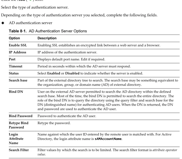
NSX Components
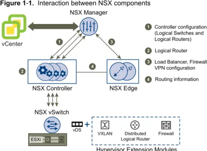
This section describes NSX components. NSX can be configured through the vSphere Web Client, a command line interface (CLI), and REST API.
can be
Figure 1‑1. Interaction between NSX components
ESXi
vDS
VXLAN Distributed Logical Router
Firewall Hypervisor Extension Modules vCenter
NSX Manager
NSX Controller NSX Edge
1
2
3
4
Controller configuration (Logical Switches and Logical Routers) Logical Router Load Balancer, Firewall, VPN configuration 1
2 3
4 Routing information
NSX vSwitch
NSX Manager
The NSX Manager is the centralized network management component of NSX, and is installed as a virtual appliance on any ESX™ host in your vCenter Server environment. It provides an aggregated system view. One NSX Manager maps to a single vCenter Server environment and multiple NSX Edge, vShield Endpoint, and NSX Data Security instances.
NSX vSwitch
NSX vSwitch is the software that operates in server hypervisors to form a software abstraction layer between servers and the physical network.
As the demands on datacenters continue to grow and accelerate, requirements related to speed and access to the data itself continue to grow as well. In most infrastructures, virtual machine access and mobility usually depend on physical networking infrastructure and the physical networking environments they reside in. This can force virtual workloads into less than ideal environments due to potential layer 2 or layer 3 boundaries, such as being tied to specific VLANs.
NSX vSwitch allows you to place these virtual workloads on any available infrastructure in the datacenter regardless of the underlying physical network infrastructure. This not only allows increased flexibility and mobility, but increased availability and resilience.
NSX Controller
NSX controller is an advanced distributed state management system that controls virtual networks and overlay transport tunnels.
NSX controller is the central control point for all logical switches within a network and maintains
information of all virtual machines, hosts, logical switches, and VXLANs. The controller supports two new logical switch control plane modes, Unicast and Hybrid. These modes decouple NSX from the physical network. VXLANs no longer require the physical network to support multicast in order to handle the Broadcast, Unknown unicast, and Multicast (BUM) traffic within a logical switch. The unicast mode replicates all the BUM traffic locally on the host and requires no physical network configuration. In the hybrid mode, some of the BUM traffic replication is offloaded to the first hop physical switch to achieve better performance.
NSX Edge
NSX Edge provides network edge security and gateway services to isolate a virtualized network. You can install an NSX Edge either as a logical (distributed) router or as a services gateway.
The NSX Edge logical (distributed) router provides East-West distributed routing with tenant IP address space and data path isolation. Virtual machines or workloads that reside on the same host on different subnets can communicate with one another without having to traverse a traditional routing interface. The NSX Edge gateway connects isolated, stub networks to shared (uplink) networks by providing common gateway services such as DHCP, VPN, NAT, dynamic routing, and Load Balancing. Common deployments of NSX Edge include in the DMZ, VPN Extranets, and multi-tenant Cloud environments where the NSX Edge creates virtual boundaries for each tenant.
NSX Edge Services
Dynamic Routing Provides the necessary forwarding information between layer 2 broadcast
domains, thereby allowing you to decrease layer 2 broadcast domains and improve network efficiency and scale. NSX extends this intelligence to where the workloads reside for doing East-West routing. This allows more direct virtual machine to virtual machine communication without the costly or timely need to extend hops. At the same time, NSX also provides North-South connectivity, thereby enabling tenants to access public networks.
Firewall Supported rules include IP 5-tuple configuration with IP and port ranges for
stateful inspection for all protocols.
Network Address Translation
Separate controls for Source and Destination IP addresses, as well as port translation.
Dynamic Host
Configuration Protocol (DHCP)
Configuration of IP pools, gateways, DNS servers, and search domains.
Site-to-Site Virtual Private Network (VPN)
Uses standardized IPsec protocol settings to interoperate with all major VPN vendors.
L2 VPN Provides the ability to stretch your L2 network.
SSL VPN-Plus SSL VPN-Plus enables remote users to connect securely to private networks
behind a NSX Edge gateway.
Load Balancing Simple and dynamically configurable virtual IP addresses and server groups.
High Availability High availability ensures an active NSX Edge on the network in case the
primary NSX Edge virtual machine is unavailable. NSX Edge supports syslog export for all services to remote servers.
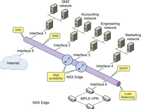
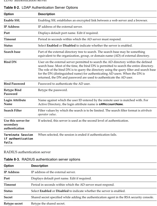
Figure 1‑2. Multi-Interface Edge
NSX Edge MPLS VPN
Internet Interface 1 Interface 3 Interface 2 Interface 4 Interface 6 Interface 5 DMZ network Accounting network Marketing network Engineering network VPN Load Balancing DNS DHCP availabilityHigh NSX Edge
Distributed Firewall
NSX Distributed Firewall is a hypervisor kernel-embedded firewall that provides visibility and control for virtualized workloads and networks. You can create access control policies based on VMware vCenter objects like datacenters and clusters, virtual machine names and tags, network constructs such as
IP/VLAN/VXLAN addresses, as well as user group identity from Active Directory. Consistent access control policy is now enforced when a virtual machine gets vMotioned across physical hosts without the need to rewrite firewall rules. Since Distributed Firewall is hypervisor-embedded, it delivers close to line rate throughput to enable higher workload consolidation on physical servers. The distributed nature of the firewall provides a scale-out architecture that automatically extends firewall capacity when additional hosts are added to a datacenter.
User Management
2
In many organizations, networking and security operations are handled by different teams or members. Such organizations may require a way to limit certain operations to specific users. This topic describes the options provided by NSX to configure such access control.
NSX also supports Single Sign On (SSO), which enables NSX to authenticate users from other identity services such as Active Directory, NIS, and LDAP.
User management in the vSphere Web Client is separate from user management in the CLI of any NSX component.
This chapter includes the following topics:
n “Configure Single Sign On,” on page 19 n “Managing User Rights,” on page 20
n “Managing the Default User Account,” on page 21 n “Assign a Role to a vCenter User,” on page 21 n “Edit a User Account,” on page 23
n “Change a User Role,” on page 24
n “Disable or Enable a User Account,” on page 24 n “Delete a User Account,” on page 24
Configure Single Sign On
Integrating the single sign on (SSO) service with NSX improves the security of user authentication for vCenter users and enables NSX to authenticate users from other identity services such as AD, NIS, and LDAP.
With SSO, NSX supports authentication using authenticated Security Assertion Markup Language (SAML) tokens from a trusted source via REST API calls. NSX Manager can also acquire authentication SAML tokens for use with other VMware solutions.
Prerequisites
n SSO service must be installed on the vCenter Server.
n NTP server must be specified so that the SSO server time and NSX Manager time is in sync. See “Edit
the NSX Manager Date and Time,” on page 151.
Procedure
2 Under Appliance Management, click Manage Settings. 3 Click NSX Management Service.
4 Click Edit next to Lookup Service.
5 Type the name or IP address of the host that has the lookup service. 6 Change the port number if required. The default port is 7444.
The Lookup Service URL is displayed based on the specified host and port.
7 Type the vCenter administrator user name and password (for example, [email protected]). This enables NSX Manager to register itself with the Security Token Service server.
8 Click OK.
Confirm that the Lookup Service status is Connected.
What to do next
Assign a role to the SSO user.
Managing User Rights
A user’s role defines the actions the user is allowed to perform on a given resource. The role determine the user’s authorized activities on the given resource, ensuring that a user has access only to the functions necessary to complete applicable operations. This allows domain control over specific resources, or system-wide control if your right has no restrictions.
The following rules are enforced:
n A user can only have one role.
n You cannot add a role to a user, or remove an assigned role from a user. You can, however, change the
assigned role for a user.
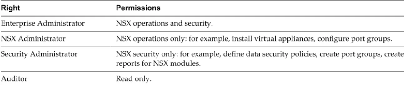
Table 2‑1. NSX Manager User Roles
Right Permissions
Enterprise Administrator NSX operations and security.
NSX Administrator NSX operations only: for example, install virtual appliances, configure port groups. Security Administrator NSX security only: for example, define data security policies, create port groups, create
reports for NSX modules.
Auditor Read only.
The scope of a role determines what resources a particular user can view. The following scopes are available for NSX users.
Table 2‑2. NSX Manager User Scope
Scope Description
No restriction Access to entire NSX system. Limit access scope Access to a specified Edge.
The Enterprise Administrator and NSX Administrator roles can only be assigned to vCenter users, and their access scope is global (no restrictions).
Managing the Default User Account
The NSX Manager user interface includes a user account, which has access rights to all resources. You cannot edit the rights of or delete this user. The default user name is admin and the default password is default or the password you specified during NSX Manager installation.
You can manage NSX Manager appliance admin user only through CLI commands.
Assign a Role to a vCenter User
When you assign a role to an SSO user, vCenter authenticates the user with the identity service configured on the SSO server. If the SSO server is not configured or is not available, the user is authenticated either locally or with Active Directory based on vCenter configuration.
1 Log in to the vSphere Web Client.
2 Click Networking & Security and then click NSX Managers.
3 Click an NSX Manager in the Name column and then click the Manage tab. 4 Click Users.
5 Click Add.
The Assign Role window opens.
6 Click Specify a vCenter user or Specify a vCenter group.
7 Type the vCenter User or Group name for the user. Refer to the example below for more information. Domain name: corp.vmware.com
Alias: corp
Group name: [email protected] User name : [email protected]
When assigning a role to a group, type the group name with the domain name. For example, [email protected]. This allows the default NSX Manager user (admin) as well as the SSO default user (admin) to login to NSX Manager. This user name is for logging in to the NSX Manager user interface, and cannot be used to access NSX Manager CLIs.
When assigning a role to a user, type the user alias. For example, user1@corp. 8 Click Next.
9 Select the role for the user and click Next. For more information on the available roles, see “Managing User Rights,” on page 20.
10 Select the scope for the user and click Finish. The user account appears in the Users table.
Understanding Group-Based Role Assignments
Organizations create user groups for proper user management. After integration with SSO, NSX Manager can get the details of groups to which a user belongs. Instead of assigning roles to individual users who may belong to the same group, NSX Manager assigns roles to groups. The following scenarios illustrate how NSX Manager assigns roles.
Example: Role-Based Access Control Scenario
This scenario provides an IT network engineer (Sally Moore) access to NSX components in the following environment.
AD domain: corp.local, vCenter group: [email protected], user name: [email protected]
Prerequisites: vCenter Server has been registered with NSX Manager, and SSO has been configured. 1 Assign a role to Sally.
a Log in to the vSphere Web Client.
b Click Networking & Security and then click NSX Managers.
c Click an NSX Manager in the Name column and then click the Manage tab. d Click Users and then click Add.
The Assign Role window opens.
e Click Specify a vCenter group and type [email protected] in Group.
f Click Next.
g In Select Roles, click NSX Administrator and then click Next. h In Limit Scope, select No restriction and click Finish. 2 Grant Sally permission to the datacenter.
a Click the Home icon and then click vCenter Home > Datacenters.
b Select a datacenter and click Actions > All vCenter Actions > Add Permission. c Click Add and select the domain CORP.
d In Users and Groups, select Show Groups First. e Select NetEng and click OK.
f In Assigned Role, select Read-only and un-select Propagate to children and click OK. 3 Log out of vSphere Web Client and log back in as [email protected].
Sally can perform NSX operations only. For example, install virtual appliances, create logical switches, and so on..
Example: Inherit PermissionsThrough aUser-Group MembershipScenario
Group option Value
Name G1
Role assigned Auditor (Read only) Resources Global root
User option Value
Name John
Belongs to group G1 Role assigned None
John belongs to group G1, which has been assigned the auditor role. John inherits the group role and resource permissions.
Example: User Member of Multiple Groups Scenario
Group option Value
Name G1
Role assigned Auditor (Read only) Resources Global root
Group option Value
Name G2
Role assigned Security Administrator (Read and Write) Resources Datacenter1
User option Value
Name Joseph
Belongs to group G1, G2 Role assigned None
Joseph belongs to groups G1 and G2 and inherits a combination of the rights and permissions of the Auditor and Security Administrator roles. For example, John has the following permissions:
n Read, write (Security Administrator role) for Datacenter1 n Read only (Auditor) for global root
Example: User Member of Multiple Roles Scenario
Group option Value
Name G1
Role assigned Enterprise Administrator Resources Global root
User option Value
Name Bob
Belongs to group G1
Role assigned Security Administrator (Read and Write) Resources Datacenter1
Bob has been assigned the Security Administrator role, so he does not inherit the group role permissions. Bob has the following permissions
n Read, write (Security Administrator role) for Datacenter1 and its child resources n Enterprise Administrator role on Datacenter1
Edit a User Account
You can edit a user account to change the role or scope. You cannot edit the admin account.
Procedure
1 Log in to the vSphere Web Client.
2 Click Networking & Security and then click NSX Managers.
3 Click an NSX Manager in the Name column and then click the Manage tab. 4 Click Users.
5 Select the user you want to edit. 6 Click Edit.
7 Make changes as necessary. 8 Click Finish to save your changes.
Change a User Role
You can change the role assignment for all users, except for the admin user.
Procedure
1 Log in to the vSphere Web Client.
2 Click Networking & Security and then click NSX Managers.
3 Click an NSX Manager in the Name column and then click the Manage tab. 4 Click Users.
5 Select the user you want to change the role for. 6 Click Change Role.
7 Make changes as necessary. 8 Click Finish to save your changes.
Disable or Enable a User Account
You can disable a user account to prevent that user from logging in to the NSX Manager. You cannot disable the admin user or a user who is currently logged into the NSX Manager.
Procedure
1 Log in to the vSphere Web Client.
2 Click Networking & Security and then click NSX Managers.
3 Click an NSX Manager in the Name column and then click the Manage tab. 4 Click Users.
5 Select a user account.
6 click the Enable or Disable icon.
Delete a User Account
You can delete any created user account. You cannot delete the admin account. Audit records for deleted users are maintained in the database and can be referenced in an Audit Log report.
Procedure
1 Log in to the vSphere Web Client.
2 Click Networking & Security and then click NSX Managers.
4 Click Users.
5 Select a user account. 6 Click Delete.
7 Click OK to confirm deletion.
If you delete a vCenter user account, only the role assignment for NSX Manager is deleted. The user account on vCenter is not deleted.
Grouping Objects
3
The Grouping feature enables you to create custom containers to which you can assign resources, such as virtual machines and network adapters, for Distributed Firewall protection. After a group is defined, you can add the group as source or destination to a firewall rule for protection.
This chapter includes the following topics:
n “Working with IP Address Groups,” on page 27 n “Working with MAC Address Groups,” on page 28 n “Working with IP Pools,” on page 29
n “Working with Security Groups,” on page 30
n “Working with Services and Service Groups,” on page 32
Working with IP Address Groups
Create an IP Address Group
You can create an IP address group and then add this group as the source or destination in a firewall rule. Such a rule can help protect physical machines from virtual machines or vice versa.
Procedure
1 Log in to the vSphere Web Client.
2 Click Networking & Security and then click NSX Managers.
3 Click an NSX Manager in the Name column and then click the Manage tab. 4 Click the Grouping Objects tab and then click IP Sets.
5 Click the Add ( ) icon and select IP Addresses. The Add IP Addresses window opens.
6 Type a name for the address group.
7 (Optional) Type a description for the address group. 8 Type the IP addresses to be included in the group. 9 Click OK.
Edit an IP Address Group
Prerequisites Procedure
1 Log in to the vSphere Web Client.
2 Click Networking & Security and then click NSX Managers.
3 Click an NSX Manager in the Name column and then click the Manage tab. 4 Click the Grouping Objects tab and then click IP Sets.
5
Select the group that you want to edit and click the Edit ( ) icon. 6 In the Edit IP Addresses dialog box, make the appropriate changes. 7 Click OK.
Delete an IP Address Group
Procedure
1 Log in to the vSphere Web Client.
2 Click Networking & Security and then click NSX Managers.
3 Click an NSX Manager in the Name column and then click the Manage tab. 4 Click the Grouping Objects tab and then click IP Sets.
5 Select the group that you want to delete and click the Delete ( ) icon.
Working with MAC Address Groups
Create a MAC Address Group
You can create a MAC address group consisting of a range of MAC addresses and then add this group as the source or destination in a Distributed Firewall rule. Such a rule can help protect physical machines from virtual machines or vice versa.
Procedure
1 Log in to the vSphere Web Client.
2 Click Networking & Security and then click NSX Managers.
3 Click an NSX Manager in the Name column and then click the Manage tab. 4 Click the Grouping Objects tab and then click MAC Sets.
5 Click the Add ( ) icon.
6 Type a name and description for the address group. 7 Type the MAC addresses to be included in the group. 8 Click OK.
Edit a MAC Address Group
Procedure
1 Log in to the vSphere Web Client.
2 Click Networking & Security and then click NSX Managers.
3 Click an NSX Manager in the Name column and then click the Manage tab. 4 Click the Grouping Objects tab and then click MAC Sets.
5
Select the group that you want to edit and click the Edit ( ) icon. 6 In the Edit MAC Addresses dialog box, make the appropriate changes. 7 Click OK.
Delete a MAC Address Group
Procedure
1 Log in to the vSphere Web Client.
2 Click Networking & Security and then click NSX Managers.
3 Click an NSX Manager in the Name column and then click the Manage tab. 4 Click the Grouping Objects tab and then click MAC Sets.
5 Select the group that you want to delete and click the Delete ( ) icon.
Working with IP Pools
You can edit or delete an IP pool.
For information on adding an IP pool, see “Configure Network Access SSL VPN-Plus,” on page 76 or
“Configure Web Access SSL VPN-Plus,” on page 83.
Create an IP Pool
Procedure
1 Log in to the vSphere Web Client.
2 Click Networking & Security and then click NSX Managers.
3 Click an NSX Manager in the Name column and then click the Manage tab. 4 Click the Grouping Objects tab and then click IP Pool.
5 Click the Add New IP Pool icon.
6 Type a name for the IP pool and type the default gateway.
7 Type the primary and secondary DNS and the DNS suffix and the prefix length. 8 Type the IP address ranges to be included in the pool and click OK.
Edit an IP Pool
You can edit an IP pool.
Procedure
1 Log in to the vSphere Web Client.
2 Click Networking & Security and then click NSX Managers.
3 Click an NSX Manager in the Name column and then click the Manage tab. 4 Click the Grouping Objects tab and then click IP Pool.
5 Select the IP pool that you want to edit. 6
Click the Edit ( ) icon.
The Edit IP Pool dialog box opens. 7 Make the required edits.
8 Click OK.
Delete IP Pool
Procedure
1 Log in to the vSphere Web Client.
2 Click Networking & Security and then click NSX Managers.
3 Click an NSX Manager in the Name column and then click the Manage tab. 4 Click the Grouping Objects tab and then click IP Pool.
5 Select the IP pool that you want to delete and click the Delete icon.
Working with Security Groups
A security group is a collection of assets or grouping objects from your vSphere inventory.
Create a Security Group
You create a security group at the NSX Manager level.
Prerequisites
If you are creating a security group based on Active Directory group objects, ensure that one or more domains have been registered with NSX Manager. NSX Manager gets group and user information as well as the relationship between them from each domain that it is registered with. See “Register a Windows Domain with NSX Manager,” on page 154.
Procedure
1 Log in to the vSphere Web Client.
2 Click Networking & Security and then click NSX Managers.
3 Click an NSX Manager in the Name column and then click the Manage tab. 4 Click the Grouping tab.
6 Type a name and description for the security group and click Next.
7 On the Dynamic Membership page, define the criteria that an object must meet for it to be added to the security group you are creating. This gives you the ability to include virtual machines by defining a filter criteria with a number of parameters supported to match the search criteria.
For example, you may include a criteria to add all virtual machines tagged with the specified security tag (such as AntiVirus.virusFound) to the security group. Security tags are case sensitive.
Or you can add all virtual machines containing the name W2008 AND virtual machines that are in the
logical switch global_wire to the security group.
8 Click Next.
9 On the Select objects to include page, select the tab for the resource you want to add and select one or more resource to add to the security group. You can include the following objects in a security group.
n Other security groups to nest within the security group you are creating. n Cluster
n Logical Switch n Network n Virtual App n Datacenter n IP sets
n Directory groups
NOTE The AD configuration for NSX security groups is different from the AD configuration for
vSphere SSO. NSX AD group configuration is for end users accessing guest virtual machines while vSphere SSO is for administrators using vSphere and NSX.
n MAC Sets n Security tag n vNIC
n Virtual Machine n Resource Pool
n Distributed Virtual Port Group
The objects selected here are always included in the security group regardless of whether or not they match the criteria in Step 4.
When you add a resource to a security group, all associated resources are automatically added. For example, when you select a virtual machine, the associated vNIC is automatically added to the security group.
10 Click Next and select the objects that you want to exclude from the security group.
The objects selected here are always excluded from the security group regardless of whether or not they match the dynamic criteria.
11 Click Finish.
Membership of a security group is determined as follows:
{Expression result (derived from step 4) + Inclusions (specified in step 6} - Exclusion (specified in step 7) which means that inclusion items are first added to the expression result. Exclusion items are then subtracted from the combined result.
Edit a Security Group
Procedure
1 Log in to the vSphere Web Client.
2 Click Networking & Security and then click NSX Managers.
3 Click an NSX Manager in the Name column and then click the Manage tab. 4 Click the Grouping Objects tab and then click Security Group.
5
Select the group that you want to edit and click the Edit ( ) icon. 6 In the Edit Security Group dialog box, make the appropriate changes. 7 Click OK.
Delete a Security Group
Procedure
1 Log in to the vSphere Web Client.
2 Click Networking & Security and then click NSX Managers.
3 Click an NSX Manager in the Name column and then click the Manage tab. 4 Click the Grouping Objects tab and then click Security Group.
5 Select the group that you want to delete and click the Delete ( ) icon.
Working with Services and Service Groups
A service is a protocol-port combination, and a service group is a group of services or other service groups.
Create a Service
You can create a service and then define rules for that service.
Procedure
1 Log in to the vSphere Web Client.
2 Click Networking & Security and then click NSX Managers.
3 Click an NSX Manager in the Name column and then click the Manage tab. 4 Click the Grouping Objects tab and then click Service.
6 Type a Name to identify the service. 7 Type a Description for the service.
8 Select a Protocol to which you want to add a non-standard port. 9 Type the port number(s) in Ports.
10 Click OK.
The service appears in the Services table.
Create a Service Group
You can create a service group and then define rules for that service group.
Procedure
1 Log in to the vSphere Web Client.
2 Click Networking & Security and then click NSX Managers.
3 Click an NSX Manager in the Name column and then click the Manage tab. 4 Click the Grouping Objects tab and then click Service Groups.
5 Click Service Groups. 6 Click the Add icon.
7 Type a Name to identify the service group. 8 Type a Description for the service.
9 In Members, select the services or service groups that you want to the group. 10 Click OK.
Edit a Service or Service Group
You can edit services and service groups.Procedure
1 Log in to the vSphere Web Client.
2 Click Networking & Security and then click NSX Managers.
3 Click an NSX Manager in the Name column and then click the Manage tab. 4 Click the Grouping Objects tab and then click Service or Service Groups. 5
Select a custom service or service group and click the Edit ( ) icon. 6 Make the appropriate changes.
7 Click OK.
Delete a Service or Service Group
You can delete services or service group.Procedure
1 Log in to the vSphere Web Client.
2 Click Networking & Security and then click NSX Managers.
3 Click an NSX Manager in the Name column and then click the Manage tab. 4 Click the Grouping Objects tab and then click Service or Service Groups. 5 Select a custom service or service group and click the Delete ( ) icon. 6 Click Yes.
Logical Switches
4
A cloud deployment or a virtual data center has a variety of applications across multiple tenants. These applications and tenants require isolation from each other for security, fault isolation, and avoiding overlapping IP addressing issues. The NSX logical switch creates logical broadcast domains or segments to which an application or tenant virtual machine can be logically wired. This allows for flexibility and speed of deployment while still providing all the characteristics of a physical network's broadcast domains (VLANs) without physical Layer 2 sprawl or spanning tree issues.
A logical switch is distributed and can span arbitrarily large compute clusters. This allows for virtual machine mobility (vMotion) within the datacenter without limitations of the physical Layer 2 (VLAN) boundary. The physical infrastructure does not have to deal with MAC/FIB table limits since the logical switch contains the broadcast domain in software.
A logical switch is mapped to a unique VXLAN, which encapsulates the virtual machine traffic and carries it over the physical IP network.
VM VM VM
VM VM
Logical switch 1
Logical switch 2
vSphere Distributed Switch NSX Manager
NSX Controller
The NSX controller is the central control point for all logical switches within a network and maintains information of all virtual machines, hosts, logical switches, and VXLANs. The controller supports two new logical switch control plane modes, Unicast and Hybrid, These modes decouple NSX from the physical network. VXLANs no longer require the physical network to support multicast in order to handle the Broadcast, Unknown unicast, and Multicast (BUM) traffic within a logical switch. The unicast mode replicates all the BUM traffic locally on the host and requires no physical network configuration. In the hybrid mode, some of the BUM traffic replication is offloaded to the first hop physical switch to achieve better performance. This mode requires IGMP snooping to be turned on the first hop physical switch. Virtual machines within a logical switch can use and send any type of traffic including IPv6 and multicast.
You can extend a logical switch to a physical device by adding an L2 bridge. See Chapter 5, “L2 Bridges,” on page 47.
You must have the Super Administrator or Enterprise Administrator role permissions to manage logical switches.
This chapter includes the following topics:
n “Create a Logical Switch,” on page 36
n “Connect Virtual Machines to a Logical Switch,” on page 38 n “Test Logical Switch Connectivity,” on page 38
n “Prevent Spoofing on a Logical Switch,” on page 39 n “Edit a Logical Switch,” on page 39
n “Working with Transport Zones,” on page 39 n “Logical Switch Scenario,” on page 42
Create a Logical Switch
Prerequisitesn You have installed the network virtualization components on the appropriate clusters n You have configured VXLAN on the appropriate clusters
See NSX Installation and Upgrade Guide.
Add a Transport Zone
A transport zone defines the span of a logical switch.
Procedure
1 Log in to the vSphere Web Client.
2 Click Networking & Security and then click Installation.
3 Click Logical Network Preparation and then click Transport Zones. 4 Click the New Transport Zone icon.
5 In the New Transport Zone dialog box, type a name and description for the transport zone.
6 Depending on whether you have a controller node in your environment, or you want to use multicast addresses, select the control plane mode.
n Multicast: Multicast IP addresses on physical network is used for the control plane. This mode is
recommended only when you are upgrading from older VXLAN deployments. Requires PIM/IGMP on physical network.
n Unicast : The control plane is handled by an NSX controller. All unicast traffic leverages headend
replication. No multicast IP addresses or special network configuration is required.
n Hybrid : The optimized unicast mode. Offloads local traffic replication to physical network (L2
multicast). This requires IGMP snooping on the first-hop switch, but does not require PIM. First-hop switch handles traffic replication for the subnet.
7 Select the clusters to be added to the transport zone. 8 Click OK.
Add a Logical Switch
A logical switch reproduces Layer 2 and Layer 3 switching functionality (unicast, multicast, broadcast) in a virtual environment completely decoupled from underlying hardware.
Procedure
1 Log in to the vSphere Web Client.
2 Click Networking & Security and then click Logical Switches. 3 Click the New Logical Switch icon.
4 Type a name and description for the logical switch.
5 Select the transport zone in which you want to create the virtualized network. The Scope Details panel displays the clusters that are part of the selected transport zone and the services available to be deployed on the scope.
6 By default, the logical switch inherits the control plane mode from the transport zone. You can change it to one of the other available modes:
n Unicast: The control plane is handled by an NSX controller. All traffic replication is handled locally
by the hypervisor. No multicast IP addresses or special network configuration is required.
n Hybrid: The optimized unicast mode. Offloads local traffic replication to physical network. This
requires IGMP snooping on the first-hop switch, but does not require PIM. First-hop switch handles traffic replication for the subnet.
n Multicast: Multicast IP addresses on physical network is used for the control plane. This mode is
recommended only when you are upgrading from older VXLAN deployments. Requires PIM/IGMP on physical network.
7 Click OK.
What to do next
Click the logical switch in the Name column to view the logical switch details.
Connect a Logical Switch to an NSX Edge
Connecting a Logical Switch to an NSX Edge services gateway or an NSX Edge logical router provides East-West traffic routing (among the logical switches) or North-South traffic routing to the external world or to provide advanced services.
Procedure
1 Log in to the vSphere Web Client.
2 Click Networking & Security and then click Logical Switches. 3 Select the logical switch that you want to connect an NSX Edge. 4 Click the Add Edge Gateway ( ) icon.
5 Select the NSX Edge to which you want to connect the logical switch and click Next. 6 Select the interface that you want to connect to the logical switch and click Next.
A logical network is typically connected to an internal interface.
7 On the Edit Edge Gateway Interface page, type a name for the NSX Edge interface. 8 Click Internal or External to indicate wether this is an internal or external interface.
9 Select the connectivity status of the interface.
10 If the NSX Edge to which you are connecting the logical switch has Manual HA Configuration selected, specify two management IP addresses in CIDR format.
11 Edit the default MTU if required. 12 Click Next.
13 Review the NSX Edge connection details and click Finish.
Deploy Services on a Logical Switch
You can deploy third party services on a Logical Switch.
Prerequisites
One or more third party virtual appliances must have been installed in your infrastructure.
Procedure
1 Log in to the vSphere Web Client.
2 Click Networking & Security and then click Logical Switches. 3 Select the logical switch on which you want to deploy services. 4
Click the Add Service Profile ( ) icon.
5 Select the service and service profile that you want to apply. 6 Click OK.
Connect Virtual Machines to a Logical Switch
You can connect virtual machines to a Logical Switch. This makes it easy to identify the port groups that belong to a Logical Switch in your vCenter inventory.
Procedure
1 Log in to the vSphere Web Client.
2 Click Networking & Security and then click Logical Switches. 3 Select the Logical Switch to which you want to add virtual machines. 4 Click the Add ( ) icon.
5 Select the vNics that you want to connect. 6 Click Next.
7 Review the vNics you selected. 8 Click Finish.
Test Logical Switch Connectivity
A ping test checks if two hosts in a VXLAN transport network can reach each other. 1 Log in to the vSphere web client.
2 Click Networking & Security and then click Logical Switches. 3 In the Name column, click the logical network that you want to test.
4 Click the Hosts tab. 5 Select a host. 6
Click the More Actions ( ) icon and select Test Connectivity.
The Test Connectivity Between Hosts in the Network dialog box opens. The host you selected in step 7 appears in the Source host field. Select Browse to select a different source host.
7 Select the size of the test packet.
VXLAN standard size is 1550 bytes (should match the physical infrastructure MTU) without
fragmentation. This allows NSX to check connectivity and verify that the infrastructure is prepared for VXLAN traffic.
Minimum packet size allows fragmentation. Hence, NSX can check only connectivity but not whether the infrastructure is ready for the larger frame size.
8 In the Destination panel, click Browse Hosts.
9 In the Select Host dialog box, select the destination host. 10 Click Select.
11 Click Start Test.
The host-to-host ping test results are displayed.
Prevent Spoofing on a Logical Switch
After synchronizing with the vCenter Server, NSX Manager collects the IP addresses of all vCenter guest virtual machines from VMware Tools on each virtual machine. NSX does not trust all IP address provided by VMware Tools on a virtual machine. If a virtual machine has been compromised, the IP address can be spoofed and malicious transmissions can bypass firewall policies.
SpoofGuard allows you to authorize the IP addresses reported by VMware Tools, and alter them if necessary to prevent spoofing. SpoofGuard inherently trusts the MAC addresses of virtual machines collected from the VMX files and vSphere SDK. Operating separately from the Firewall rules, you can use SpoofGuard to block traffic determined to be spoofed.
For more information, see “Using SpoofGuard,” on page 64.
Edit a Logical Switch
You can edit the name, description, and control plane mode of a logical switch.
Procedure
1 Log in to the vSphere Web Client.
2 Click Networking & Security and then click Logical Switches. 3 Select the logical switch that you want to edit.
4 Click the Edit icon. 5 Make the desired changes. 6 Click OK.
Working with Transport Zones
Add a Transport Zone
A transport zone defines the span of a logical switch.
Procedure
1 Log in to the vSphere Web Client.
2 Click Networking & Security and then click Installation.
3 Click Logical Network Preparation and then click Transport Zones. 4 Click the New Transport Zone icon.
5 In the New Transport Zone dialog box, type a name and description for the transport zone.
6 Depending on whether you have a controller node in your environment, or you want to use multicast addresses, select the control plane mode.
n Multicast: Multicast IP addresses on physical network is used for the control plane. This mode is
recommended only when you are upgrading from older VXLAN deployments. Requires PIM/IGMP on physical network.
n Unicast : The control plane is handled by an NSX controller. All unicast traffic leverages headend
replication. No multicast IP addresses or special network configuration is required.
n Hybrid : The optimized unicast mode. Offloads local traffic replication to physical network (L2
multicast). This requires IGMP snooping on the first-hop switch, but does not require PIM. First-hop switch handles traffic replication for the subnet.
7 Select the clusters to be added to the transport zone. 8 Click OK.
View and Edit a Transport Zone
You can view the logical networks in a selected transport zone, the clusters in, and the control plane mode for that transport zone.
Procedure
1 Log in to the vSphere Web Client.
2 Click Networking & Security and then click Installation.
3 Click Logical Network Preparation and then click Transport Zones. 4 Double-click a transport zone.
The Summary tab displays the name and description of the transport zone as well as the number of logical switches associated with it. Transport Zone Details displays the clusters in the transport zone. 5 Click the Edit Settings icon in the Transport Zone Details section to edit the name, description, or
control plane mode of the transport zone.
If you change the transport zone control plane mode, select Migrate existing Logical Switches to the new control plane mode to change the control plane more for existing logical switches linked to this transport zone. If you do not select this check box, only the logical switches linked to this transport zone after the edit is done will have the new control plane mode.
Expand a Transport Zone
You can add clusters to a transport zone, which stretches all existing transport zones to become available on the newly added clusters.
Prerequisites
The clusters you add to a transport zone have the network infrastructure installed and are configured for VXLAN. See the NSX Installation and Upgrade Guide.
Procedure
1 Log in to the vSphere Web Client.
2 Click Networking & Security and then click Installation.
3 Click Logical Network Preparation and then click Transport Zones. 4 Click a transport zone.
5
In Transport Zones Details, click the Add Cluster ( ) icon. 6 Select the clusters you want to add to the transport zone. 7 Click OK.
Contract a Transport Zone
You can remove clusters from a transport zone. Existing transport zones may be shrunk to accommodate the contracted scope.
Procedure
1 Log in to the vSphere Web Client.
2 Click Networking & Security and then click Installation.
3 Click Logical Network Preparation and then click Transport Zones. 4 Double-click a transport zone.
5
In Transport Zones Details, click the Remove Clusters ( ) icon. 6 Select the clusters you want to remove.
7 Click OK.
Logical Switch Scenario
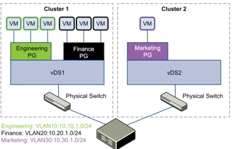
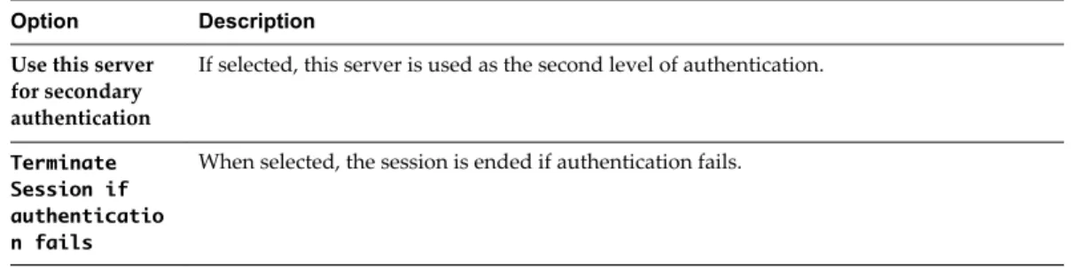
This scenario presents a situation where company ACME Enterprise has several ESX hosts on two clusters in a datacenter, ACME_Datacenter. The Engineering (on port group PG-Engineering) and Finance
departments (on port group PG-Finance) are on Cluster1. The Marketing department (PG-Marketing) is on Cluster2. Both clusters are managed by a single vCenter Server 5.5.
Figure 4‑1. ACME Enterprise network before implementing logical switches
Engineering
PG FinancePG
Physical Switch Cluster 1
Engineering: VLAN10:10.10.1.0/24
Finance: VLAN20:10.20.1.0/24
Marketing: VLAN30:10.30.1.0/24
vDS1
VM VM VM
Physical Switch vDS2
VM
Marketing PG
Cluster 2
VM VM VM
ACME is running out of compute space on Cluster1 while Cluster2 is under-utilized. The ACME network supervisor asks John Admin (ACME's virtualization administrator) to figure out a way to extend the Engineering department to Cluster2 in a way that virtual machines belonging to Engineering on both clusters can communicate with each other. This would enable ACME to utilize the compute capacity of both clusters by stretching ACME's L2 layer.
If John Admin were to do this the traditional way, he would need to connect the separate VLANs in a special way so that the two clusters can be in the same L2 domain. This might require ACME to buy a new physical device to separate traffic, and lead to issues such as VLAN sprawl, network loops, and
administration and management overhead.
John Admin remembers seeing a logical network demo at VMworld, and decides to evaluate NSX. He concludes that building a logical switch across dvSwitch1 and dvSwitch2 will allow him to stretch ACME's L2 layer. Since John can leverage the NSX controller, he will not have to touch ACME's physical
Figure 4‑2. ACME Enterprise implements a logical switch
Engineering
PG FFiinnaanncceePPGG
Physical Switch Cluster 1
vDS1
VM VM VM
Physical Switch vDS2
VM
M Maarrkkeettiinngg
P PGG
Cluster 2 Logical Switch stretches across multiple VLANs/subnets
VM VM VM
Engineering: VXLAN5000:10.10.1.0/24
Finance: VXLAN5001:10.20.1.0/24
Marketing: VXLAN5002:10.30.1.0/24
Engineering PG
VM VM VM
VM VM
Once John Admin builds a logical switch across the two clusters, he can vMotion virtual machines within the vDS.
Figure 4‑3. vMotion on a logical network
vMotion range vMotion range
Engineering
PG FFiinnaanncceePPGG
vDS1
VM VM VM
vDS2 VM
M Maarrkkeettiinngg
P PGG
VM VM VM
Engineering: VXLAN5000:10.10.1.0/24
Finance: VXLAN5001:10.20.1.0/24
Marketing: VXLAN5002:10.30.1.0/24
Engineering PG
VM VM VM
VM VM
Let us walk through the steps that John Admin follows to build a logical network at ACME Enterprise. Chapter 4 Logical Switches
John Admin Assigns Segment ID Pool and Multicast Address Range to NSX
Manager
John Admin must specify the segment ID pool he received to isolate Company ABC's network traffic.
Prerequisites
1 John Admin verifies that dvSwitch1 and dvSwitch2 are VMware distributed switches version 5.5. 2 John Admin sets the Managed IP address for the vCenter Server.
a Select Administration > vCenter Server Settings > Runtime Settings. b In vCenter Server Managed IP, type 10.115.198.165.
c Click OK.
3 John Admin installs the network virtualization components on Cluster1 and Cluster 2. See NSX Installation and Upgrade Guide.
4 John Admin gets a segment ID pool (5000 - 5250) from ACME's NSX Manager administrator.Since he is leveraging the NSX controller, he does not require multicast in his physical network.
5 John Admin creates an IP pool so that he can assign a static IP address to the VXLAN VTEPs from this IP pool. See “Add an IP Pool,” on page 77.
Procedure
1 Log in to the vSphere Web Client.
2 Click Networking & Security and then click Installation.
3 Click the Logical Network Preparation tab and then click Segment ID. 4 Click Edit.
5 In Segment ID pool, type 5000 - 5250. 6 Do not select Enable multicast addressing. 7 Click OK.
John Admin Configures VXLAN Transport Parameters
John Admin configures VXLAN on Cluster 1 and Cluster 2, where he maps each cluster to a vDS. When he maps a cluster to a switch, each host in that cluster is enabled for logical switches.
Procedure
1 Log in to the vSphere Web Client.
2 Click Networking & Security and then click Installation. 3 Click the Host Preparation tab.
4 For Cluster1, select Configure in the VXLAN column.
5 In the Configuring VXLAN networking dialog box, select dvSwitch1 as the virtual distributed switch for the cluster.
6 Type 10 for dvSwitch1 to use as the ACME transport VLAN.
7 In Specify Transport Attributes, leave 1600 as the Maximum Transmission Units (MTU) for dvSwitch1. MTU is the maximum amount of data that can be transmitted in one packet before it is divided into smaller packets. John Admin knows that VXLAN virtual wire traffic frames are slightly larger in size