0 INTRODUCTION
Existing piping systems sometimes need to operate at larger mechanical loads than they are originally designed to. Often, these beyond-the-original-design loads lessen the margin against piping failure so much that performing recalculations using original analysis methods cannot qualify the pipeline. To demonstrate suitability of the existing pipeline to increased loads and to avoid piping hardware modification, more advanced analysis methods need to be employed.
In this paper, a single detail from the beyond-the-original-design analysis [1] of a buried thin-wall water pipeline in nuclear power plant (NPP) Krško is shown. That analysis, the description of which is beyond the aim of this paper, demonstrated that the most critical part of the system is the penetration of the buried pipeline into a power plant’s concrete building. Namely, because of a supposed beyond-the-original-design earthquake, relative displacements between the building’s basement wall and the surrounding soil evolve, which in turn imposes large deformation on a buried pipe at the site of the building wall’s penetration. The most significant mode of deformation is pipe denting at the pipe-to-concrete-wall seal location.
Pipe denting strongly influence pipeline’s strength and fatigue life; therefore, the topic was addressed by researchers in the past [2] and [3] and is still attractive today [4] to [6]. The solutions to the problem are in the form of a pure theoretic analysis [2], or as guides extracted from recapitulation of many experiments [3], or, recently, from experiments supplemented with numerical analyses [4] to [6]. All researchers agree that the excessive size of the dent, the abrupt change of the dented surface curvature and the pre-existing pipe damage on the dent spot severely lessen pipe strength and fatigue life. Because the denting is a problem still under research, it is not included in piping structural design codes yet, therefore leaving the structural engineer on thin ice.
The aim of this paper is twofold: describing the experimental-numerical analysis of the dented section of a pipeline at NPP Krško and demonstrating the pipeline qualification with the applicable American Society of Mechanical Engineers (ASME) Code [7] (which is the obligatory code for NPP Krško), although no rule regarding dents is given in [7].
An Exacting Wall-Penetration Pipe Analysis
Koc, P.
Pino Koc*
University of Ljubljana, Faculty of Mathematics and Physics, Slovenia
Conventional analysis methods for piping systems have incorporated many conservative assumptions. Some of these assumptions can be abandoned by employing advanced analyses, thus allowing for higher loads, which can lead to further uprating of the system without physically intervening with it.
This paper shows the procedure of uprating the design seismic load of an existing pipeline through advanced analyses. First, it was discovered that the seal between the pipe and the wall in fact represents a support which is even stiffer than an engineered, purposely built support. Secondly, analyses demonstrate that a pipeline built of thin wall pipes can sustain significant lateral deformation (ovalization and indentation), imposed by seismically induced relative displacements between the buried pipe and building wall penetration, without breaching the pipe wall. This finding is supported by the fact that the pipe passed the flattening test. In the pipeline qualification procedure, the stress state in the dented pipe wall is compared with the stress state during the flattening test. All relevant stress indicators (stress intensities) at the uprated loading state were smaller than allowed by the applicable code or obtained from the flattening test; thus, the pipeline qualified for uprated seismic conditions.
Keywords: dented pipeline, seismic, ASME, stress categorization, Link-Seal
Highlights
• During a strong earthquake, the Link-Seal sealing system is insufficient to compensate for relative displacements between the pipe and the wall. It becomes a support.
• Ovalization and pipe wall indentation at the piping supports are significant modes of deformation for thin-walled pipes. • Successfully passing the pipe flattening test serves to determine an upper-limit stress state in the pipe.
1 METHODS
1.1 General Procedure and Acceptance Criteria
Stresses beyond those allowable were obtained at the pipeline penetration by analysing a beyond-the-design loading condition using ordinary design methods, i.e., finite element modelling with pipeline approximation based on beam’s finite elements (AutoPipe code, for example) [1]. However, investigation of the problem revealed that by employing unconventional piping analysis methods, an acceptable solution can be found without pipe penetration modification while respecting applicable standards and codes [7]. The whole analysis procedure can be divided into the following steps:
1) Defining material data through a literature search and by the numerical simulation of the experiment; where the experiment itself was performed by others.
2) Cooperating with analysts of the global pipeline model to tune both the global and the local (detailed) model and harmonize their responses. 3) Determining the strain-stress state in the local
model.
4) Interpreting the obtained strain-stress state according to code [7] rules.
Acceptance criteria are given in the ASME Code [7] in the form of allowable stresses which are dependent on the material, external loading behaviour and the sort of stress which develops inside the investigated cross-section. In our case, the pipe material is carbon steel SA 106 Grade B [8]. The loading is given in the form of a set of axial and lateral earthquake-induced relative displacements, with a magnitude of several centimetres, between the basement concrete wall and the pipe. The sorts of stresses which need to be checked in the case of extreme loading are primary membrane stress Pm and primary bending stress Pb.
The functionality criterion given in plant specifications and reprinted in [1] is that a pipeline must maintain operability during and after a major earthquake. This means that the pipeline may deform, even permanently, but must convey cooling water in all circumstances.
1.2 Defining Mechanical Properties
1.2.1 Yield Curve
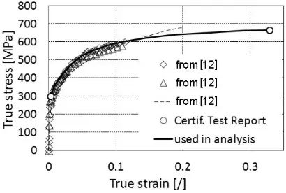
The ASME [8] provides enough material properties data to perform elastic analyses. However, regarding
elastic-plastic material response, only tensile strength is given in [8]. To define the yield curve properly, additional information was found in [12] and in a certified test report on the piping material [1]. The yield curve, which was used in all computer simulations, is shown in Fig. 1.
Fig. 1. Yield curve justification
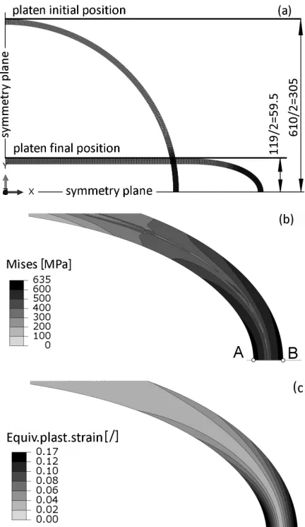
1.2.2 Pipe Flattening Test
When the pipeline is manufactured, each pipe from which the pipeline is assembled needs to pass a pipe-flattening test. In the test, described in the steel SA-106 specification [8], a short section, 63.5 mm (2.5 inch) in length, is sliced from each pipe to be used in a pipeline, to obtain a ring, which is then flattened cold between parallel platens until the required distance between the platens is achieved. In our case, for a pipe with outer diameter D = 610 mm (24 inch) and wall thickness t = 9.52 mm (3/8 inch), this distance is 119 mm. No signs of fracture should be seen on the flattened pipe. The test itself is excellent proof of how much local bending a pipe can sustain. Therefore, it is safe to assume that the stress-strain state from the flattening test represents an upper limit which should not be exceeded during any loading conditions.
1.2.3 Numerical Simulation of Pipe Flattening Test
final stress and strain states are shown in Figs. 2b and c, respectively.
Fig. 2. Flattening test simulation: a) kinematics; b) equivalent von Mises stress; and c) equivalent plastic strain
The most stressed and strained part of the pipe is the most curved part of the pipe wall, where the von Mises equivalent stress is 635 MPa, and the equivalent plastic strain at the same material point is 0.17. The mentioned stress of 635 MPa is called the total stress and according to the ASME [7] needs to be decomposed into primary membrane Pm, primary bending Pb and peak stress F using a stress-linearization procedure. First, a stress path line is defined, denoted by the AB line through the pipe wall (Fig. 2b). The intensity of the radial and circumferential components of the stress tensor along the AB path is depicted in Fig. 3, where point A corresponds with the zero wall-thickness coordinate. From the circumferential stress diagram, it can be
seen that inelastic bending is the prevailing loading on the path.
Fig. 3. Stress components on the most critical stress path for the flattening test
Next, for each stress tensor component sij the membrane (average stress across the pipe wall thickness) and bending stress (stress, linearized across the wall so that the net force is zero) need to be calculated according to Eq. (1) and Eq. (2), respectively:
σij memb σ
t
ij
t dx
, =
∫
,1
0
(1)
σij bend σ
t
ij
t t x dx
, = − ,
∫
62
2 0
(2)
with t denoting the wall thickness at the end of simulation and x representing the local axis aligned along the stress path line from point A towards point B.
Finally, when all components of the membrane and bending stress tensors are obtained, the equivalent von Mises stress is calculated for each of the tensors. For the abovementioned flattening test, the procedure yields the following stress intensities: equivalent stress from membrane stress tensor Pm = 55.7 MPa and equivalent stress from the sum of the membrane and bending stress tensors at point A (inner surface of the pipe), (Pm + Pb)A = 846 MPa, and at point B (outer surface of the pipe), (Pm + Pb)B = 912 MPa. It is worth mentioning that Pm is reasonably low due to the prevailing bending of the pipe wall and that the allowable membrane stress according to the ASME [7] is 0.7sult = 0.7×666 = 466 MPa.
result is a consequence of the stress-linearization procedure applied to the highly plastically deformed pipe wall. These high stresses cannot be used independently; they can serve only as stress limits in cases with a similar loading pattern, i.e., inelastic pipe wall bending.
1.3 Interaction between Global and Local Model
1.3.1 Ovalization and Indentation Stiffness
The analysed pipeline is made of thin-walled pipes (D/2t = 610 / (2×9.52) = 32) which are susceptible to local radial loading. Thus, for the considered several-centimetre range of relative displacements, ovalization of the pipe cross-section and indentation of the pipe wall, rather than the bending of the pipe centreline, are the dominant modes of pipe deformation at the supports. These two modes are the main deformation patterns regarding how to “consume” the imposed relative displacement at the wall penetration point. The pipe centreline is displaced through these two deformation modes, although parts of the pipe wall in contact with a supporting structure will remain at the same place.
The global pipeline model built of beam finite elements [1] cannot handle ovalization and indentation deformation modes, but it can consider elastic supports, i.e., springs. Therefore, to mitigate the consequences of large relative displacements at the penetration point, springs with stiffness equivalent to the ovalization and indentation stiffness of the pipe wall are determined in separate detailed numerical models and then included in the global beam model at the piping support and seal.
1.3.2 Equivalent Stiffness at the Guide Restraint
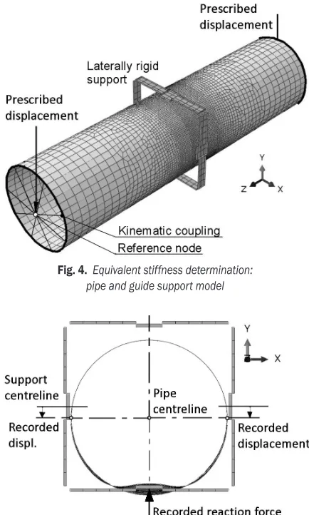
Equivalent stiffness was determined through separate analysis of the pipe section with its support in a shell 3D model (Fig. 4). While the pipe is deformable, and its material obeys the elastic-plastic material behaviour from Fig. 1, the guide restraint support itself, i.e., the square-like structure around the pipe, which allows for axial movement of the pipe but prevents lateral displacement, is considered rigid due to the heavy I-beams which constitute the support. The contact surfaces with prescribed initial gaps between the pipe wall and the guide support pads are modelled as well. At the nodes on both pipe ends, kinematic constraints are imposed such that the displacement of these nodes is coupled on translation and rotation of the reference nodes, positioned at the pipe centreline.
The pipe’s loading is given in the form of the vertical displacement of both reference nodes. During the simulation, displacements of two pipe points on a pipe cross-section at the support and the support reaction force are monitored (Fig. 5) and presented as a graph, shown in Fig. 9. This graph is used in the global pipeline beam model [1] to determine the guide support’s equivalent lateral spring stiffness.
Fig. 4. Equivalent stiffness determination: pipe and guide support model
Fig. 5. Equivalent stiffness determination: pipe centreline displacement on guide support
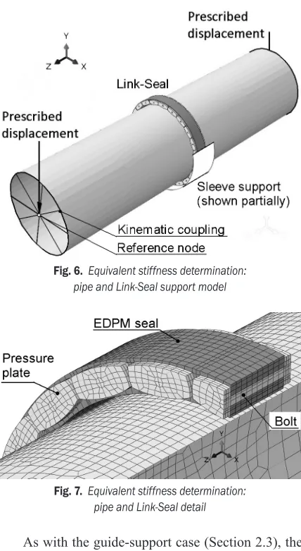
1.3.3 Equivalent Stiffness at Link-Seal
metal sleeve, with which the Link-Seal is in contact, is embedded in a concrete wall and acts as a rigid support for the Link-Seal (Figs. 6 and 7).
Pre-compression of the EDPM and its expansion in a radial direction during the installation of the Link-Seal are not considered in the model.
Fig. 6. Equivalent stiffness determination: pipe and Link-Seal support model
Fig. 7. Equivalent stiffness determination: pipe and Link-Seal detail
As with the guide-support case (Section 2.3), the loading of the pipe is given in the form of displacement of both pipe ends. In Fig. 8, the cross section of the pipe at the Link-Seal is shown in the position at which the centreline downward displacement is 24.7 mm. The Link-Seal pressure plates at the lower part of the seal circumference create an obstacle against which the pipe wall locally bends. On the upper part of the cross-section, a gap between the seal and the pipe wall is formed. The reaction force vs. pipe centreline displacement graph, corresponding to the simulated downward movement of the pipe, is given in Fig. 9. The Link-Seal support is, in fact, much stiffer than the guide support. Therefore, it would be a big mistake if
the Link-Seal were not considered in a beam model [1] as a support.
Note that in Fig. 7, only the shell mid-thickness surface is shown for the pipe wall’s finite elements. The contact algorithm accounts for the shell’s thickness; therefore, the pipe in Fig. 7 is in contact with the EDPM seal along the circumference, and the seal is in contact with the metal sleeve.
Fig. 8. Equivalent stiffness determination: pipe centreline displacement on Link-Seal
Fig. 9. Support lateral response
2 ANALYSIS
2.1 Finite Element Model
The model is supported at the sleeve and at the support pads. Contact is possible between the pipe and support pads, between the sleeve and Link-Seal elements and between the pipe and Link-Link-Seal elements. The friction coefficient is 0.8 between the seal and the pipe and 0.2 between the pipe and support pads. A kinematic coupling between the pipe nodes and a reference node is established at both ends of the pipe.
Fig. 10. Model of the pipe at wall penetration
2.2 Model Loads
The internal surface of the pipe is loaded with a pressure of 240 kPa.
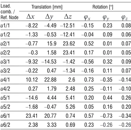
Table 1. Critical displacement and rotation combinations Load.
comb. / Ref. Node
Translation [mm] Rotation [°]
Δ
x
Δ
y
Δ
z
φ
xφ
yφ
zu1/1 –8.22 –4.49 –12.51 –0.15 0.23 0.08
u1/2 –1.33 –0.53 –12.41 –0.04 0.09 0.06
u2/1 –0.77 15.9 23.62 0.52 0.01 0.07
u2/2 –0.3 1.58 23.41 0.17 0.01 0.05
u3/1 –9.32 –14.53 –1.42 –0.56 0.32 0.09
u3/2 –0.22 0.47 –1.34 –0.16 0.11 0.07
u4/1 10.12 22.88 2.6 0.73 –0.35 –0.14
u4/2 0.27 1.79 2.48 0.25 –0.11 –0.10
u5/1 –14.6 4.44 5.41 0.20 0.44 0.26
u5/2 –1.68 –0.47 5.26 0.05 0.16 0.20
u6/1 23.41 20.77 0.74 0.57 –0.73 –0.34
u6/2 2.38 3.33 0.69 0.23 –0.26 –0.26
The prescribed displacements and rotations of the pipe end reference nodes are the pipe’s most important loading. From the global beam model [1], with which the earthquake analysis of the whole pipeline was performed, extreme seismic displacements and rotations of two nodes corresponding to two reference nodes were retrieved and incorporated into the pipe shell model as prescribed spatial translations and rotations. Six displacement and rotation combinations, denoted as u1 through u6, were identified in a beam model as critical combinations; see Table 1.
In the finite element simulation of the pipe shell, the strain and stress state in the pipe from one loading combination was transmitted in the next loading combination. Thus, the plastic strain and possible damage to the pipe wall were accumulated. The analysis was dynamic; thus, one loading combination was smoothly transferred into another. The total duration of one loading combination was 0.1 s, which roughly resembles the time between individual shocks during an earthquake.
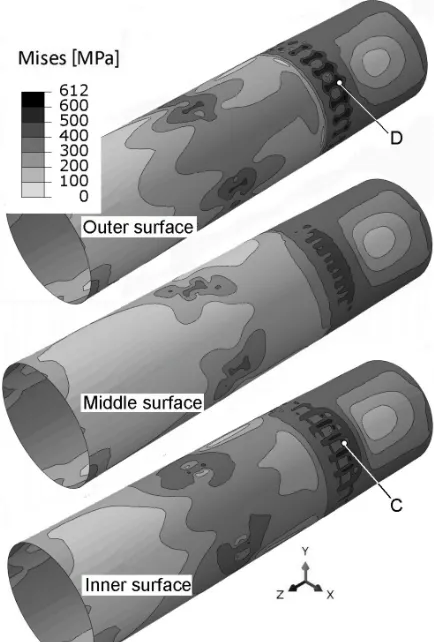
3 RESULTS
Selected results from a database of finite element analysis results are displayed. Fig. 11 shows a pipe with a deformed shape (exaggerated by a factor of 10). In that figure, all pipe deformation modes except pipe ovalization are clearly seen. The most severe appears to be the indentation at the Link-Seal where a series of smaller axial dents form one large circumferential dent. Due to the displacement magnification factor 10, this dent seems non-smooth (with kinks). When the deformed shape of the pipe was inspected at magnification factor 1 (no magnification), smooth change of curvature at dents locations were observed. Therefore, the dents are categorized as plain dents. The deepest dent is indented at h = 12 mm, which represents 12/610×100 % = 2 % of the pipe diameter. In ref. [3], where results of many experiments are interpreted, plain dents up to 10 % are considered acceptable. In [6], dents of the same h/t ratio but for smaller D/t ratio are anticipated to preserve 80 % of the dent-free pipe bending moment. Therefore, it seems that the dents in Fig. 11 do not represent a pipe bursting peril.
(Fig. 2c). It should be noted that high plastic strain, say, greater than 0.05, is localized around several Link-Seal pressure plates. The white-coloured regions represent no plastic strain.
Because the stress cannot accumulate like the plastic strain, the stress states from all displacement combinations in Table 1 need to be checked for extreme stress. The extreme von Mises equivalent stresses found in the pipe are listed in Table 2.
Fig. 12. Equivalent plastic strain at the end of the simulation
Table 2. Penetration pipe, total stress for all displacement combinations
Loading comb.
von Mises stress at pipe wall surface [MPa] Inner Middle Outer
u1 324 240 342
u2 355 376 441
u3 360 357 494
u4 490 453 576
u5 443 409 571
u6 549 489 612
Note: The pipe’s middle surface refers to the imaginary surface at the half thickness of the pipe wall.
Because the highest stresses were found in the last displacement combination, the stress state and stress-qualification procedure will be presented in detail for that combination only.
Fig. 13. Von Mises equivalent stress at the end of the simulation
Fig. 13 provides the von Mises equivalent stress at the end of the simulation. The three pictures represent the stress field at the outer, middle and inner shell surface.
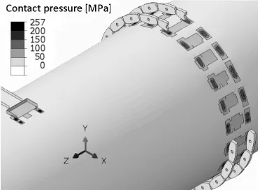
wall and cause local bending of the pipe wall. Lateral reaction forces produce local contact pressure (Fig. 14) and local shear stress (not shown) on the pipe wall.
The stresses obtained from the finite element simulation are total stresses; therefore, the total stresses are decomposed into bending Pb, local membrane PL and peak stress F. Fig. 15 shows components of the total stress tensor acting on the C-D stress path through the pipe wall’s thickness. The zero-wall thickness coordinate corresponds to the inside of the wall (point C in Fig. 13). As in Fig. 3, inelastic bending is the prevailing loading in the path.
Fig. 14. Contact pressure at the end of the simulation
Fig. 15. Stress tensor components at the most critical stress path C-D at the end of the simulation
The same stress linearization procedure as described in Section 1.2.3 yields the following stress intensities, expressed in the form of the von Mises equivalent stress intensities: equivalent stress from membrane stress tensor PL = 232 MPa and equivalent stress from the sum of the membrane and bending stress tensors at point C (inner surface of the pipe), (Pm + Pb)C = 695 MPa, and at point D (outer surface of the pipe), (Pm + Pb)D = 813 MPa.
Finally, in Table 3, the analysis results are presented in a short form. All the stress and strain criteria are fulfilled; thus, the pipeline penetration qualifies for augmented (beyond-the-design) seismic loading.
4 DISCUSSION
Qualification of the most stressed part of the pipeline, i.e., the pipe penetration through the concrete wall, is based on the ASME rules [7] and common engineering reasoning.
The most discussible part of the methodology, presented in the paper, is the stress linearization procedure, with which the total stress is decomposed into those of the primary membrane Pm, primary local PL, primary bending Pb and peak stress F. In the ASME Code, it is assumed that the linearization procedure will be performed on stresses obtained on pure elastic material. However, in ASME Sect. III, Appendix F [7], which deals with extreme loading conditions and allows for elastic-plastic material response, the stresses must be decomposed into Pm, PL and Pb. However, no explicit rule is given in the code about how to linearize stresses in case of elastic-plastic material response [11]. In this regard, the same physical equivalence principle regardless of the evidenced degree of non-linearity in the actual stress distribution is adopted in this work. The author is fully aware that by increasing the degree of non-linearity, uncommon results might be obtained from
Table 3. Penetration pipe, stress intensities
Stress category Allowable [MPa] Calculated [MPa] Comment Primary membrane Pm
466 < 350 Remote from supports Primary bending Pb
Local membrane PL 466 232 Stress path C-D
Primary local plus primary bending PL + Pb 912 813 Point D
695 Point C
Total stress 635 612 Non-ASME requirement
thus specified stress linearization. Nevertheless, in the flattening test simulation (Section 1.2.3) and in the penetration pipe simulation (Section 3), this stress linearization procedure was strictly followed regardless of the results obtained in this way. The adopted approach is justified by the fact that the same stress linearization procedure was used for both simulations, i.e., in the assessment of the limiting state for the flattening test and in checking whether the pipe penetration stress state reached the limits. Thus, the same methodological inconsistencies (if any) are cancelled out.
5 CONCLUSIONS
Piping systems are usually designed using the simplest approach permitted by codes and standards. This leaves quite large margins in terms of real sustainability of piping systems. The paper shows how these margins can be exploited to uprate mechanical loads acting on the pipeline without changing any hardware (supports, piping sections, piping layout) while still obeying the codes. Particular analysis methods were used to obtain this goal.
6 ACKNOWLEDGEMENTS
The author acknowledges financial support from the Slovenian Research Agency (research core funding No. P2-0263) and the Nuklearna Elektrarna Krško. Also, the author wishes to express thanks to NEK personnel for their support and collaboration.
All analyses were performed in the Laboratory for Numerical Modelling and Simulation of Faculty for Mechanical Engineering, University of Ljubljana.
7 REFERENCES
[1] Celarec, D., Koc, P., Jalovec, R., Kodrič, M., Planinc, R.,
Daniels, E. (2014). Assesment of capacity of the NEK to resist
permanent ground deformations due to potential surface faulting. Report number: NEK ESD-TR-10/13, Revision 2. NEK and Worley parsons, Krško (NEK proprietary document).
[2] Liu, J.H., Francis, A. (2004). Theoretical analysis of local indentation on pressured pipes. International Journal of Pressure Vessels and Piping, vol. 81, no. 12, p. 931-939,
DOI:10.1016/j.ijpvp.2004.05.007.
[3] Cosham, A., Hopkins, P., (2003). The effect of dents in pipelines – Guidance in the pipeline defect assessment manual. ICPVT-10 Conference Proceedings, p. 127-139.
[4] Pinheiro, B., Pasqualino, I., Cunha, S. (2014). Fatigue life assessment of damaged pipelines under cyclic internal pressure: Pipelines with longitudinal and transverse plain dents. International Journal of Fatigue, vol. 68, p. 38-47,
DOI:10.1016/j.ijfatigue.2014.06.003.
[5] Garbatov, Y., Guedes Soares, C. (2017). Fatigue reliability of dented pipeline based on limited experimental data.
International Journal of Pressure Vessels and Piping, vol. 155, p. 15-26, DOI:10.1016/j.ijpvp.2017.07.001.
[6] Cai, J., Jiang, X., Lodewijks, G., Pei. Z., Wu W. (2018). Residual ultimate strength of damaged seamless metallic pipelines with combined dent and metal loss. Marine Structures, vol. 61, p. 188-201, DOI:10.1016/j.marstruc.2018.05.006.
[7] ASME Boiler and Pressure Vessel Code (1972). Section III, Subsection ND-Class 3 Components and Appendix F-Rules for Evaluation of Service Loading with Level D Limits. American Society of Mechanical Engineers. New York.
[8] ASME Boiler and Pressure Vessel Code (1972). Section II, Part A-Ferrous Material Specifications and Part D-Properties.
American Society of Mechanical Engineers. New York.
[9] Dassault Systemes, ABAQUS, Ver. 6.11, from https://www.3ds. com/products-services/simulia/products/abaqus/, accessed on 2018-11-09.
[10] GPT Industries, Wall Penetration Seals, Link-Seal from https:// www.gptindustries.com/en/products/link-seal, accessed on 2018-11-09.
[11] Faidy, C. (Coordinator) (2017). Non-Linear Analysis Design Rules. World Nuclear Association, London.