An Approach to the Optimization of a Thin-walled Z-beam
Nina Anÿeliü*
- Vesna Miloševiü Mitiü- Taško Maneski University of Belgrade, Faculty of Mechanical Engineering, Serbia
One approach to the optimization of a thin-walled open section Z-beam subjected to bending and to the constrained torsion is considered. For given loads, material and geometrical characteristics the problem is reduced to the determination of minimum mass i.e. minimum cross-sectional area of a structural thin-walled beam of a chosen shape. The area of the cross section is assumed to be the objective function. The stress constraints are introduced. A general case when bending moments about two centroidal axes and the bimoment are acting simultaneously is derived, and then some particular loading cases are considered. A method of solving the optimal relation of the parts of the considered cross-section is described. Applying the Lagrange multiplier method, the equations, whose solutions represent the optimal values of the ratios of the parts of the chosen cross-section, are formed. The obtained results are used for numerical calculation.
© 2009 Journal of Mechanical Engineering. All rights reserved.
Keywords: optimization, thin-walled beams, optimal dimensions, stress constraints, saved mass
0 INTRODUCTION
Many modern metal structures (motor and railroad vehicles, naval structures, turbine blades) are manufactured using thin-walled elements (shells, plates, thin-walled beams) which are subjected to complex loads. In most structures it is possible to find the elements in which, depending on loading cases and the way they are introduced, the effect of constrained torsion is present and its consequences are particularly evident in the case of thin-walled profiles.
Investigations of the behaviour of thin -walled members with open cross-sections have been carried out extensively since the early works of S. P. Timoshenko [1], who was among the first to publish a number of books on materials strength, the theory of elasticity and the theory of stability, and who also developed the theory of beams and plates bending. V. Z. Vlasov [2] contributed largely to the theory of thin-walled structures by developing the theory of thin-walled open section beams. Kollbruner and Hajdin >3] and [4@ expanded the field of thin-walled structures by a range of their works. Exceptionally valuable among them are two monographs >3] and [4@ which with a series of contributions originally describing the authors' area of interest, constitute a unique work in terms of content,. Also, Murray >5@ and Rhodes et al. >6@ should be mentioned as the authors who
behaviour of thin-walled structures. Due to their low weight, thin-walled open section beams are widely applied in many structures. Thin-walled beams have a specific behaviour, which is the reason why their optimization is a particular problem.
Analyzing the process of designing various types of structures, it can be observed that the classical procedure of defining dimensions of a structure based on the theory of the strength of materials provides sufficient, however, not the optimum geometric parameters. In general, the optimization is a mathematical process through which a set of conditions, which give the maximum or minimum value of a specified function as a result, are obtained. In the ideal case the perfect solution for the considered design situation is supposed to be obtained but in reality only the best solution although not the perfect one, can be found. Among the authors who developed theoretical fundamentals of the optimization method, Fox [7], Brousse [8], Prager [9] and Rozvany >10@ should be given the most prominent place.
experimental study on the minimum weight and the associated optimal geometric dimensions of an open-channel steel section.
Many authors, including Farkas [14], applied mathematical problems to the conditional extreme of the function with more variables onto the cross-sectional area of the structure and defined optimum cross-section from the aspect of load and consumption of the material. Then, a series of works appear where the problem of optimization of various cross-sections, such as triangular cross-section [15], I-section [16] and [17] or channel-section beams [18] are solved by using the Lagrange multiplier method.
The main purpose of this paper is to present one approach to the optimization of a thin-walled Z-section beam.
1 PROBLEM FORMULATION
The starting points during the formulation of the basic mathematical model are the assumptions of the thin-walled-beam theory, on one hand, and the basic assumptions of the optimum design on the other.
During the process of structure dimensioning, apart from defining the requested dimensions necessary to permit the particular part of the structure to support the applied loads, it is often of significance to determine the optimal values of the dimensions. The Z - cross section as a very often used thin-walled profile in steel structures is in this paper considered as the object of the optimization. The determination of its optimal dimensions is a very important process but not always the simplest one. The aim of the paper is to determine the minimum mass of the whole beam, i.e. the minimum area A of the cross-section of the considered beam for the given loads and material properties.
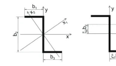
The cross-section of the considered beam (Fig. 1) with principal centroidal axes Xi (i = 1, 2) has the centre and not the axis of symmetry. It is assumed that its flanges have equal widths b1=b3, and thicknesses t1= t3, and that its web has the width b2 and thickness t2. The ratios of thicknesses and widths of flanges and web are treated as non-constant quantities.
Fig. 1. Cross-section
It is also assumed that the loads are applied in two longitudinal planes, parallel to the centroidal axes x and y at the distances ȟibi (i= 1, 2) (Fig. 1).If applied in such a way, the loads will cause the bending moments acting in the above mentioned two planes parallel to the longitudinal axis of the beam, and consequently the effects of the constrained torsion will occur in the form of the bimoment, causing the stresses that depend on the boundary conditions [3] and [19].
The aim of the paper is to determine the minimal mass of the beam or, in other words, to find the minimal cross-sectional area
min A
A (1)
for the given loads and material and geometrical properties of the considered beam, while satisfying the constraints.
The formulation of the structural design optimization problem plays an important role in the numerical solution process >6@. A particular choice of the objective function and constraints affects the final solution, and the efficiency and robustness of the solution process.
1.1 Objective Function
The process of selecting the best solution from various possible solutions must be based on a prescribed criterion known as the objective function. In the considered problem the cross-sectional area will be treated as an objective function and it is evident from the Fig. 1 that
, 1, 2, 3
i i A
b t ior (because b1 = b3) 2 2 1 1 2 1, ) 2
(b b b t b t A
A . (2)
, 1, 2, 3
i i t
const i
b v , (3)
where tiandbi are thickness and widths of flanges and web.
1.2 Constraints
The formulation is restricted to the stress analysis of thin-walled beams with open sections. Only normal stresses will be taken into account in the consideration that follows and the constraints treated in the paper are the stress constraints. The expressions (4) and (5) for equivalent bending moments [20] taking into account the influence of the bending moments around centroidal axes x and y, denoted as Mxand
My respectively, will be used
y x 2 xy y xy y x x I I I 1 I I M M M ¸ ¸ ¹ · ¨ ¨ © § (4) and y x 2 xy x xy x y y I I I 1 I I M M M ¸ ¸ ¹ · ¨ ¨ © § , (5) where Ix, Iy are the moments of inertia of the
cross-sectional area about the centroidal axes x andy, and Ixy is the product of inertia.
The normal stresses are caused by the bending moments Mx and My and by the bimoment B that appears in the case of constrained torsion, and they will be denoted as
x
V and Vy andVZ respectively [3] and [19]. Bimoment is not a static value, and can not be defined by static equilibrium conditions. When the bending moments act in planes parallel to the longitudinal axis (Fig. 1) at the distances ȟibi (i = 1, 2) the bimoment will appear as a consequence, and it can be expressed as the function of the bending moments and the eccentrities of their planes ȟibi (i = 1, 2) in the following way [3] and [19]
M b M b
B [ [ .
For the allowable stress V0 the constraint
function can be written as
0 max max
max V V V
V V M
M x y Z d .
(7) The maximal normal stresses, are defined in the form [3] and [19]
x x x W M max V , y y y W M max V , (8) Z Z V W B max , (9) where Wx and Wy are the section moduli for the
longitidunal axes, and WZ is the sectorial section modulus for the considered cross-section.
After the introduction of Eqs. (8) and (9) into Eq. (7), the constraint function becomes
0 V M Z d W B W M W M y y x x . (10) The constraint function Eq. (10) is reduced to:
1 2
2 2 1 1 2
1 1 2 2 1 1
2 2 1 1 2
1 1 2 2
1 1
2 2 2
1 1 2
1 1 ( , ) 1 30 3 2 9 3 3 2 1 6 1 2 x y b b M t b t b b
t b t b t b M z
t b t b b
t b t b
t b B
t b t b b
t b
MM
¬ ® ¸ ¸ ¬ ® ¬ ® 0 0. V b (11) The expression (10) represents the constraint function corresponding to the given stress constraints.
2 RESULTS AND DISCUSSION
2.1 Analytic Solution
the objective function with respect to the constraint. The Lagrange multiplier method is a powerful tool for solving this class of problems without the need to explicitly solve the conditions and use them to eliminate extra variables. It is a method for finding the extremum of the function of several variables when the solution must satisfy a set of constraints, and for the analogous problem in the calculus of variations.
Applying the Lagrange multiplier method to the vector which depends on two parameters bi (i = 1, 2) the system of equations
1, 2 1, 2 0, 1, 2 i
A b b b b i
b OM
s ¯
¢ ±
s , (12)
will be obtained and after the elimination of the multiplier O, it will become
1 2 1 2 2 1 2 2 1 1 21, , , ,
b b b b b b A b b b b b b A w w w w w w w
w M M
. (13)
Let the ratio
1 2 b b
z (14)
be the optimal ratio of the parts of the considered cross-section and let
1 2 t t
\ , (15)
be the ratio of the flange and web thicknesses. After the introduction of the Eq. (6) for the bimoment into the Eq. (11), the Eq. (13) can be reduced to an equation whose solutions give the optimal values of the ratio (14). The solutions are in the form of the sixth order
¦
6 1 0 k k kz c . (16) The coefficients ck in (16) are defined as: 1 2 0 60144[ [c ,
1 1 2
1 2
2 145 276 264
36 3 4 y,
x c M M \ [ [ [ [
1 2 2 1 255 38 27 2
3 4 23 3 4 y
x M c M [ [ \ [ [ £ ² ¦ ¦ ¦ ¦ ¦ ¦ ¦ ¦ ¤¦ ¯ »¦ ¦ ¢ ± ¦ ¦ ¦ ¦ ¦ ¥ ¼ ,
1 2 2 3 1 24 50 75 84
123 76 3 4 y
x M c M \ [ [ \ [ [ £ ² ¦ ¦ ¦ ¦ ¦ ¦ ¦ ¦ ¤¦ ¯ »¦ ¦ ¢ ± ¦ ¦ ¦ ¦ ¦ ¥ ¼ ,
1 2 3 4 1 28 31 24
208 75 3 4 y
x M c M \ [ [ \ [ [ £ ² ¦ ¦ ¦ ¦ ¦ ¦ ¦ ¦ ¤ ¯ » ¦ ¦ ¦ ¢ ± ¦ ¦ ¦ ¦ ¦ ¥ ¼ ,
» » ¼ º « « ¬ ª x y M M c5 2\4 16\[1 312 3[1 4[2 ,5
6 8 2 3 1 4 2 .
y
x
M c
M
\ [ [ (17)
It is obvious that the coefficients ck (k = 1, 2, …, 6) depend on the ratio of the bending moments My/Mx and on the eccentrities ȟ1andȟ2 of their planes.
The results that follow were obtained by an analytical approach.
2.2 Optimal Values
From the general case, when bending moments about both axes appear simultaneously with the bimoment, some particular cases can be considered, depending on the ratio My/Mx.
The optimal ratios b2/ b1 defined by (14) and obtained from the Eq. (16) are calculated for
My/Mx=0, 0.1, 0.5, 1; ȥ = 0.5, 0.75, 1 and ȟ1,ȟ2 = 0, 0.2, 0.4, 0.6, 0.8, 1.0, or in other way, for 0 ȟ1 1; 0 ȟ2 1.
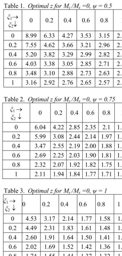
The optimal values of z for My/Mx=0 and ȥ = 0.5, 0.75 and 1.0, are shown in Tables 1, 2 and 3 as the functions of ȟ1 and ȟ2.
The highest and the lowest optimal values z = b2/b1 for My/Mx = 0.1, 0.5, 1 are given in a
shortened form in Table 4.
Table 1. Optimal z for My/Mx =0, ȥ = 0.5 ȟ1o
ȟ2p
0 0.2 0.4 0.6 0.8 1
0 8.99 6.33 4.27 3.53 3.15 2.92 0.2 7.55 4.62 3.66 3.21 2.96 2.79 0.4 5.20 3.82 3.29 2.99 2.82 2.69 0.6 4.03 3.38 3.05 2.85 2.71 2.62 0.8 3.48 3.10 2.88 2.73 2.63 2.55 1 3.16 2.92 2.76 2.65 2.57 2.50
Table 2. Optimal z for My/Mx =0, ȥ = 0.75 ȟ1o
ȟ2p
0 0.2 0.4 0.6 0.8 1
0 6.04 4.22 2.85 2.35 2.1 1.95
0.2 5.99 3.08 2.44 2.14 1.97 1.86
0.4 3.47 2.55 2.19 2.00 1.88 1.80
0.6 2.69 2.25 2.03 1.90 1.81 1.74
0.8 2.32 2.07 1.92 1.82 1.75 1.70
1 2.11 1.94 1.84 1.77 1.71 1.67
Table 3. Optimal z for My/Mx =0, ȥ = 1 ȟ1o
ȟ2p
0 0.2 0.4 0.6 0.8 1
0 4.53 3.17 2.14 1.77 1.58 1.46 0.2 4.49 2.31 1.83 1.61 1.48 1.40 0.4 2.60 1.91 1.64 1.50 1.41 1.35 0.6 2.02 1.69 1.52 1.42 1.36 1.31 0.8 1.74 1.55 1.44 1.37 1.32 1.28 1 1.58 1.46 1.38 1.32 1.28 1.25
Table 4. Optimal z = b2/b1 for My/Mx = 0.1, 0.5,
1 and ȥ = 0.5; 0.75; 1
My/Mx ȥ z
0.1
0.5 0.75
1
2.61d zd 5.54 1.75d zd 4.38 1.31 d zd 3.70
0.5
0.5 0.75
1
2.53d z d. 2.74 1.70d z d 2.19 1.28d z d 1.86
1
0.5 0.75
2 d z d 2.49 1.60d z d 1.67
2.3 The Loading Cases
The obtained results are used for the calculation that follows. Some particular cases can be considered, depending on the loading case. In the present section, a cantilever Z-beam is fixed at one end and subjected to the concentrated bending moments Mx = 100 Nm, My= 0 Nm (My/Mx
= 0).
The loading cases were considered when concentrated bending moments were applied at the free end for three positions of the load plane with respect to the shearing plane (Fig. 2). The optimal values zopt are calculated as previously
explained.
3 NUMERICAL EXAMPLE AND ANALYSIS OF RESULTS
As a numerical example, the considered cantilever beam with the length l = 1500 mm, fixed at one end, is subjected to the bending moments Mx = 100 Nm, My= 0.
The initial cross-sectional geometrical characteristics are calculated taking into account the initial dimensions of the Z-section beam. It is assumed that the considered section has the initial cross-sectional geometrical characteristics: b1 = 51.75 mm, b2 = 92 mm, t1 = 8 mm, t2=6.5 mm. It represents the Initial model with the “Initial area” of the cross-section. For the given loads (Figs. 3 and 4) and the defined geometry of the profile, the initial stresses are calculated.
Starting from the initial relation zinitial and for the initial wall thicknesses t1 and t2 the optimal relation zoptimalis calculated defining the “Optimal area” of the cross-section.
3.1 Determination of the Minimum Cross Sectional Area
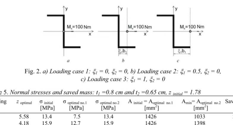
Fig. 2. a) Loading case 1: [1 = 0, [2 = 0, b) Loading case 2: [1 = 0.5, [2 = 0,
c) Loading case 3: [1 = 1, [2 = 0
Table 5. Normal stresses and saved mass: t1 =0.8 cm and t2 =0.65 cm, z initial = 1.78
Loading zoptimal ıinitial ıoptimal no.1 ıoptimal no.2 A initial = Ⱥoptimal no.1 Amin=Ⱥoptimal no.2 Saved mass Case [MPa] [MPa] [MPa] [mm2] [mm2] [%] 1 5.58 13.4 7.5 13.4 1426 1033 27.56 2 4.18 15.9 12.7 15.9 1426 1398 1.96 3 1.54 38.2 37.9 38.2 1426 1418 0.56 2) From the condition prescribing that the stresses
must be lower than the allowable one, i.e. the “Initial stress”, the optimal values b1optimal and b2optimal are obtained by using the calculated optimal relation z and by comparing the stress defined by the optimal geometrical characteristics to the “Initial stress”. It represents the Optimal model no. 2. Starting from the optimal cross sectional dimensions (b1optimal and b2optimal), the optimal – minimum cross-sectional area Ⱥmin is calculated for each loading case and the results including the saved mass of the material are given in Table 5. From the Table 5 it can be seen that for all the loading cases the level of stresses is decreased in the Optimal model no. 1 with the area of the cross-section having the same value as in the Initial model, and the saved mass of material is increased with respect to the initial stress limits in the Optimal model no. 2 where the area is smaller than the initial one. The calculation showed that the maximum saved material is obtained in the Loading case 1 and the minimum in the Loading case 3. This allows the conclusion that if the distance of the loading plane from the shearing plane is increased, the optimization of the cross-section is less necessary.
4 CONCLUSIONS
The paper presents one approach to the optimization of the thin-walled Z – section beams, loaded in a complex way, using the Lagrange multiplier method.
Accepting the cross-sectional area as the objective function and the stress constraints as the constrained functions, it is possible to calculate the optimal ratios of the webs and the flanges of the considered thin-walled profiles in a very simple way.
In addition to the general case, some particular loading cases are considered. As a result of the calculation the modified constrained functions are derived as the polynomials of the sixth order.
Particular attention is directed to the calculation of the saved mass using the proposed analytical approach. It is also possible to calculate the saved mass of the used material for different loading cases.
The aim of the paper is the optimization of thin-walled elements subjected to the complex loads, and it may be concluded that the paper gives the general results permitting the derivation of the expressions that can be recommended for technical applications.
5 REFERENCES
[1] Timoshenko, S.P., Gere, J.M. Theory of elastic stability, 2nd ed. Mc Graw-Hill, New York, 1961, ISBN-10 0070647496.
[3] Kollbruner, C.F., Hajdin, N. Dunnwandige Stabe, Band 1, Springer Verlag, Berlin, 1972.
[4] Kollbruner, C.F., Hajdin, N. Dunnwandige Stabe, Band 2, Springer Verlag, Berlin, 1975.
[5] Murray, N.W. Introduction to the theory of thin-walled structures, Clarendon Press, Oxford, 1984, ISBN 0-19-856186-5. [6] Rhodes, J., Spence, J. Behaviour of
thin-walled structures, Elsevier Applied Science, London, 1984, ISBN: 0-85334-246-6.
[7] Fox, R.L. Optimization methods for
engineering design, Addison-Wesley
Publishing Company Inc, Reading,
Massachusetts, 1971.
[8] Brousse, P. Structural optimization, CISM, No. 237,Springer-Verlag, Wien, 1975, ISBN 3-211-81376-4.
[9] Prager, W. Introduction to structural optimization, CISM, No. 212, Springer-Verlag, Wien, 1974, ISBN 978-3-211-81291-4.
[10] Rozvany, G. Shape and layout optimization of structural systems and optimality criteria methods, CISM, No. 325, Springer-Verlag, Wien, 1992, ISBN 978-3-211-82363-7.
[11] Deng,Y., Zheng, D. Minimizing the
thicknesses of injection-molded plastic parts based on a moldflow simulation, Strojniški vestnik - Journal of Mechanical Engineering, 2007, vol. 53, no. 7-8, p. 503-518.
[12] Paczelt, I., Baksa, A., Szabo, T. Product design using a contact-optimization technique, Strojniški vestnik - Journal of Mechanical Engineering, 2007, vol. 53, no. 7-8, p. 442-461.
[13] Tian,Y.S., Lu, T.J. Minimum weight of cold-formed steel sections under compression,
Thin-walled structures, 2004, vol. 42, no. 4, p. 515-532.
[14] Farkas, J. Optimum design of metal
structures, Akademiai KIADO, Budapest, 1984.
[15] Selmic, R., Cvetkovic, P., Mijailovic, R., Kastratovic G. Optimum dimenzions of triangular cross-section in lattice structures, Meccanica,2006, vol. 41, no. 4, p. 391-406. [16] Ružiü, D., Anÿeliü, N., Miloševiü V. One
more view on the problem of optimization of
an I-beam, Bulletins for Applied
Mathematics, 1996, LXXIX, PC-116, God, TU Budapest, Hungary, p. 367-372.
[17] Andjeliü, N. Thin walled I-beam under complex loads - Optimization according to stress constraint, FME Transactions, 2003, vol. 31, no. 2, p. 55-60.
[18] Andjeliü, N., Miloseviü-Mitiü V. Optimization of a thin-walled cantilever beam at constrained torsion, Structural integrity and life, 2006, vol. 6, no. 3, p. 121-128.
[19] Ružiü, D. Strength of structures, University of Belgrade, Faculty of Mechanical Engineering, Belgrade, 1995, ISBN 86-7083-266-6, (in Serbian).
[20] Bojaniü, Z. Theory of elasticity 2002, vol. 2, University of Belgrade, Faculty of Mechanical Engineering, Belgrade, ISBN 86-7083-416-2, (in Serbian),.
[21] Onwubiko, C. Introduction to engineering design optimization, Prentice Hall, Inc, New Jersey, 2000, ISBN 0-201-47673-8.