Automatic Extraction of Features and Generation of Feature Models
from Java Programs
Paulius Paškeviius, Robertas Damaševiius, Eimutis Kariauskas,
Romas Marcinkeviius
Software Engineering Department, Kaunas University of Technology, Lithuania E-mail: [email protected], [email protected], [email protected],
http://dx.doi.org/10.5755/j01.itc.41.4.1108
Abstract. Feature modelling is a key technique for identifying common and variable features in software (software component families). The result of feature modelling is a feature model: a concise specification of product features and their relationships. Feature models have been proven to be useful for software variability modelling and management. However, there is a wide gap between feature models and program source code. Here we focus on reverse engineering of source code to feature models. We present a framework for the automated derivation of feature models from the existing software artefacts (components, libraries, etc.), which includes a formal description of a feature model, a program-feature relation meta-model, and a method for feature model generation based on feature dependency extraction and clustering. Feature models are generated in Feature Description Language (FDL) and as Prolog rules.
Keywords: program analysis, reverse engineering, feature modelling, model generation.
1. Introduction
Programming is the process of turning features, concepts, aspects, patterns, models and designs into source code. The process is performed either 1) manually, by a programmer writing source code, 2) semi-automatically, e.g., by a code generator genera-ting code templates from a high-level model and then the programmer filling in the missing details, or 3) automatically, e.g., by a compiler compiling source code into executables.
The process of discovering higher-level concepts (features, patterns, models, etc.) in source code is
called de-programming [1]. Extracting program
dependency graphs [2], causal dependencies [3], facts [4], detecting code clones [5], finding design patterns [6] and architectural models [7], architecture recovery [8], reengineering [9], reconstruction [10], ontology learning [11], vertical program transformations [12] are examples of such activity. More broadly, such activity can be understood as a part of reverse
engineering, i.e., “the process of analyzing a subject
system to create representations of the system at a higher level of abstraction.” [13].
In this paper we focus on reverse engineering of software to feature models. The activity also has been
defined as ‘feature model mining’ [14] and ‘product
line reengineering’ [15]. A feature model is a representation of concepts in a domain in terms of features, their variabilities and dependencies [16]. Feature models can be represented visually using Feature Diagrams [17] as well as formally [18] or textually [37]. Feature modelling is a key technique for identifying common and variable features in a software family and formalizing such analysis in the form of a feature model.
location is an important activity in software evolution and software maintenance.
The problem of feature extraction is known under several names in computer science research: feature mining [14], fact extraction [4], model extraction [20], concept analysis [21], feature location [22, 23], con-cept location [24], dependency finding [3], concon-cept assignment [25], semantic clustering and topic mining [26], pattern discovery [27, 28], etc.
Biggerstaff et al. [25] define a concept assignment
problem as the problem of “discovering
human-oriented concepts and assigning them to their realizations”. The process is difficult to be automated, because the concept (feature) and program source code are not at the same level of abstraction. To perform concept assignment, an expert knowledge of the specific domain and a reasoning mechanism are needed. Usually, some form of human input is needed to enrich source code with additional information in order to help tools to extract and arrange higher-level concepts. For example, Basten and Klint [4] perform fact extraction from Java programs by attaching fact extraction annotations to a single syntax rule and extracting local facts from parse tree fragments.
The feature-feature and feature-code relationships can be modelled using various mathematical
struc-tures. For example, Sangal et al. [2] use a dependency
structure matrix. Snelting and Tip [21] use Formal Concept Analysis (FCA) to analyze legacy code aiming to reconstruct the overall system structure by determining which variables (columns) were accessed by which modules (rows). Pfaltz [3] describes a methodology based on the formal concept analysis that uncovers possible causal dependencies in exe-cution trace streams. Structures used for information
retrieval include call-graph information to
automa-tically assign features to respective elements in source code [29] and complex networks of software depen-dence [30].
In the context of feature modelling and product
line engineering, She et al. [14] use association rule
mining to retrieve the necessary propositional formu-las to find feature groups, mandatory features, implies/exclude edges, and to construct a probabilistic feature model from a set of individual configurations, which consist of a list of features defined as system
properties that a stakeholder is interested in. Yang et
al. [31] recover domain feature models using FCA,
concept pruning/merging, structure reconstruction and variability analysis. Poshyvanyk and Marcus [32] combine an information retrieval based technique with scenario-based probabilistic ranking of the execution traces to improve the precision of feature location. Salah and Mancoridis [33] combine both static (dependencies) and dynamic (execution traces) information to identify features in Java programs and use FCA to relate features together.
Summarising, though a number of methods exist to locate and retrieve higher-level concepts from source code such as features, none of them are actually
automatic and allow building feature models from the source code itself. The novelty of this paper is a proposed method for the automatic derivation of feature models from Java source code.
2. Framework for automatic derivation of feature models
To define a framework, first, we must define a model of domain, specify basic types of program dependencies, construct program-feature meta-model, and provide a detailed description of the methodology.
2.1. Domain model
Our domain of research is programs, which are understood in terms of structural programming. A program consists of components. Each component has variables to store component’s state, computations performed on variable values and references to other components. Data are passed between components via variables. In an object-oriented language such as Java, we have a program consisting of multiple classes. Each class can have attributes (fields), methods, and references to other classes. Each method, in turn, can have its own local variables, references to other classes and methods. For simplicity reasons, we consider both a class and a method as a component, though Java does not allow stand-alone methods (functions). Also we do not differentiate between classes per se, abstract classes and interfaces.
2.2. Program dependencies
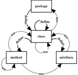
We follow a detailed taxonomy of relations in Java programs, which is presented by [20]. All relation types represent a dependency, with the dependency direction being the direction of the relation; in this way, the extracted relations form a dependency graph. In general, dependencies can be direct, transitive, or cyclic [34]. A direct dependency exists between two items, dependent and dependee. A transitive depen-dency occurs when two items are linked via one or more intermediary nodes. A cyclic dependency is a relation between two or more modules which either directly or indirectly depend on each other to function. Relations and dependencies in Java program entities are summarized in Fig. 1.
2.3. Feature model
The feature model consists of a hierarchy of features, a set of selection functions (AND, OR, CASE) to select a feature, and a set of constraints expressed by propositional formulas, which must be satisfied in a legal configuration. Formally, a feature is
a coloured vertex
x
ic (x
ic Xc) of the totalcoloured feature graph G(Xc,Vc), where Xcis a set
of vertices, and Vc is a set of edges. A relationship
between features is a sub-graph Gr(Xrc,Urc), where
c d c p c
r x X
X is a set of vertices, xcpXc is a
parent vertex, Xdc Xc is a set of vertices (grouped
features) that are descendants (children) of xcp ,
c c c
r U V
U is a set of edges that connects xcp to
each member of Xdc.
Feature diagram is a bi-coloured directed graph )
, (Xc Vc
G formed by the composition of the
bi-coloured featured tree T(Xc,Uc) and a set of edges
B representing constraints between vertices
c c
B X
X , where Uc is a set of directed edges
representing parent-child relationships of a pair of vertices; Vc UcB.
The process of feature selection for product implementation can be described as colouring of a feature diagram. There are two colours to specify the current state of a feature in a feature graph: white – unselected, black – selected. There are two colours of edges defined in terms of modal logic: white and black. Based on the feature diagram colouring rules, there are three types of features: mandatory, optional and alternative. A white-coloured edge means that a descendant vertex xdc ,
c d c
d X
x , may be possibly
selected if its parent vertex xcp is selected, i.e. c p
x ¡
c d
x . A black-coloured edge means that a descendant
vertex xcd must be necessarily be selected if its parent
vertex xcp is selected, i.e. xcpxdc.
A descendant feature that is related with its parent
feature by a black-coloured edge is called a mandatory
feature. Optional feature is a member of feature group
c c
d X
X that is related with its parent feature xcp by
a white-coloured edge. Any optional features may be selected independently from other optional features in
its feature group, i.e., xcp ¡ xic , xicXdc .
Alternative feature is a member of feature group
c c
d X
X that is related with its parent feature xcp by
a white-coloured edge. Exactly one alternative feature
must be selected from its feature group, i.e., xcp
c i
x , xicXdc and xcp¡xcj, xcjXdc,jzi.
A feature that has no parents is called the root
feature. There is only one root feature in the graph G. A feature that is a parent of either an optional or an
alternative feature group is called a variant point. A
feature that has no descendants is a variant.
Constraint is a predicate of a prescribed type
between two variants xic and xcj in G, i.e.,
^
true false`
x x
bt: ic, cj o , , btB;xic,xcjXc. The
predicate evaluates to true, if the constraint exists,
otherwise the predicate evaluates to false. The requires
constraint indicates that the selection of one variant requires that some another variant must be selected,
i.e.,
colorxic oblackocolorxcj oblack , iftrue x
x
breq ic, cj o . The excludes constraint indicates
that the selection of one variant excludes the selection of some another variant, i.e.,
colorxic oblackocolorxcj owhite , iftrue x
x
bexc ic, cj o .
Feature path Tpis a sub-graph of G that contains
only black-coloured vertices, i.e. features selected by a stakeholder. Feature path is a complete feature path, if it contains no variant points. Complete feature path is
constructed from a feature graph G , when a
stakeholder makes all available selections of features. Configuration c is a multi-set of all features in the
feature path Tp . Configuration c is a valid
configuration, if 1) it is not empty, 2) it contains no variant points, 3) the multiplicities of elements belonging to the multi-set are equal to 1, i.e., it contains only unique features, 4) all features in the
multi-set satisfy a set of constrains B in graph G.
The configuration set C is a set of all valid
configurations of feature graph G.
2.4. Program-Feature Meta-Model
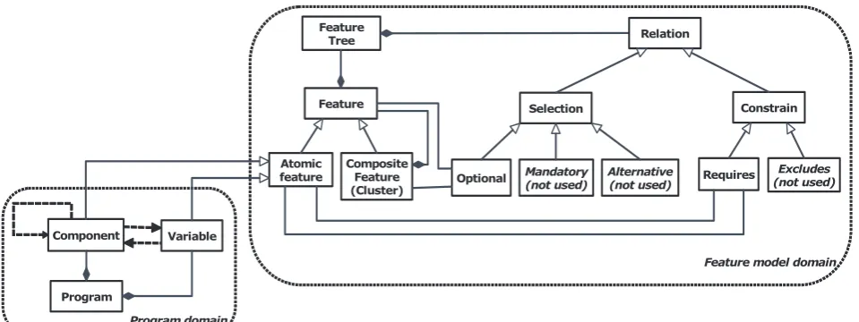
Combining the concepts described in subsection 2.2 and introduced in subsection 2.3, we propose a program-feature relation meta-model (see Fig. 2). The concepts of this meta-model are explained as follows.
An atomic feature is a basic unit of computation in a program such as variable or function (method). A composite feature is a composition of atomic features. A software component (class) is a particular (meaningful) composition of related atomic and/or composite features. A dependency is a relationship
between atomic or composite features. Feature A
depends on feature B if feature A references feature B.
For example, method A() uses the value of variable B
Feature model domain
Program domain Program
Component Variable
Feature
Composite Feature (Cluster) Atomic
feature Feature
Tree Relation
Selection Constrain
Requires
Optional Mandatory(not used) Alternative(not used) (not used)Excludes
Figure 2. Program-feature relation meta-model
2.5. Methodology
Our methodology of feature model extraction from Java programs is as follows:
1) Compile Java source code using a standard Java compiler
2) Extract feature dependencies from Java class files
Feature dependencies are modelled using a
dependency graph G. The dependency graph G is a
directed graph that is described formally as follows:
F DG , , where F – is a set of vertices
representing features, and D is a set of dependencies.
Feature dependencies are extracted by parsing a Java class file. A class file is a component of a Java executable corresponding to a single Java class. It contains tables describing the structure of the class and virtual machine byte code for the class methods. Parsing Java class files is a reliable and straightforward way to find dependencies among Java classes [35].
3) Construct a feature distance matrix
For further manipulations, the dependency graph
G is expressed as the adjacency matrix A of size F,
where aij 1, if feature i depends on feature j. The
adjacency matrix allows to describe only direct dependencies. To describe indirect dependencies, the
matrix A is converted to the distance (dissimilarity)
matrix M of size F , where mij is equal to the
shor-test path distance between feature i and feature j.
Both matrices A and M are asymmetric, because the
dependency graph G is directed. The matrix A is
converted to the matrix M using the Floyd’s all pairs
shortest path algorithm.
4) Cluster features based on their dependency in a feature tree
Given a dependency graph G (V,E), a cluster is
defined as a sub-graph Gc (Vc,Ec), whose nodes are tightly connected, i.e. cohesive. A cluster tree is a
directed acyclic graph T C,R , where C is a set of
clusters and R is a set of relations between clusters.
Each cluster corresponds to a subset of atomic and/or composite features that are more related to each other
than other features. The root of the tree T is a single
cluster that contains all features from F. The nodes of
the tree correspond to the composite features. The
leaves of the cluster tree T correspond to the atomic
features.
To derive composite features, we cluster atomic features based on their dependency information. Selection of number of clusters is a separate problem, because the size of the feature model directly depends upon the number of discovered clusters. Too fine-grained clustering leads to overly detailed specification of features in a feature model, thus making it incomprehensible and not reusable. To set a number of clusters, we follow a simple rule of thumb
2 /
n
k| , where n is the number of atomic features,
and k is the number of clusters (composite features).
For clustering, we define class methods as features; and instantiations of other classes, calls to other methods, and use of class variables as attributes.
In practice, any clustering algorithm, which can produce hierarchical dendrogram as a result (e.g., fast greedy algorithm which maximizes modularity
measure, Girvan-Newman edge betweenness
algorithm and walktrap community detection are some
of the alternatives), can be used at this stage, the ad
hoc recommendation is to use the incremental
building balanced trees such as Cobweb [36] from the WEKA package.
5) Convert a feature tree into a feature model
Finally, the cluster tree T is converted to a feature
model FM, where all nodes from a set of clusters C
are mapped to feature nodes, relation between clusters is described by an optional relationship, and constraints are added using information from the adjacency matrix A (f1 <requires> f2 if af1,f2 1) .
The problem is how to set feature relationships, i.e., which features are to be marked as mandatory, and which optional (alternative). The analyzed program represents only one possible combination of program’s features, whereas a feature model represents a set of possible feature combinations. We tackle this problem as follows. We denote root node relations as mandatory and all other relations as alternative. We however claim that additional constrains between features should be discovered at a later stage, i.e., during feature modelling.
6) Generate description of feature model in FDL/Prolog
The results are saved using a Feature Description
Language (FDL) [37] format for further representation and usage in the feature modelling environment FD2, which is currently under development, and in Prolog as a set of rules [38] for further formal analysis and calculation of feature model metrics.
The methodology is summarized in Fig. 3.
Java .class files Java source
code
Dependency graph
Extrac-tion
Distance matrix
Cluster dendrogram
Feature model
Compu-tation
Cluster analysis
Transl ation
Compi-lation
Figure 3. Summary of methodology for feature model extraction
3. Case study
For our case study, we have selected the Java Buffer library, which is a part of JDK 1.5 class library (package java.nio.*). The Java Buffer library is a benchmark source code component used by researchers [39, 40] in the area of program analysis, generalization and meta-programming research. The
library contains 74 classes describing different buffers. Below, we briefly describe features of the Buffer classes and explain how those features are reflected in the Buffer classes (for a more detailed description, see [41]).
The class hierarchy of the Buffer library is organized in 3 levels. At Level 1 in the class hierarchy, there are seven classes that contain methods for providing access to buffer functionalities implemented in the classes at Level 2. At Level 2, classes implement two memory allocation schemes (direct, non-direct) and two byte orderings (native, non-native, Little Endian, Big Endian). Byte ordering matters for buffers, whose elements consist of multiple bytes. Twenty classes result from combining memory access and byte ordering features. Seven Heap classes implement the non-direct memory access scheme for a buffer. Classes with suffixes ‘U’ and ‘S’ implement direct memory access scheme with native and non-native byte ordering, respectively. At Level 3 in the class hierarchy, 25 classes implement different access modes of buffers. Summarizing, the Buffer library components have multiple features alongside many dimensions, their features depend upon each other, thus feature location and identification of feature locations is not an easy task. We formulate our aim as the identification of clusters of similar classes as composite features, and construction of a feature model consisting of composite and atomic features (we consider a stand-alone class or method as an atomic feature, though a class field may be an atomic feature, too).
Here as an example, we demonstrate the results of feature model extraction using 4 classes
(DirectIntBufferRS, DirectIntBufferS, DirectIntBufferU, DirectIntBufferRU) from the Java
Buffer library. The classes describe different direct buffers for storing integer type elements.
We use JDependencyFinder
(http://depfind.source-forge.net/) as a third-party tool to parse, analyze and extract dependencies from Java class files. The dependency graph is represented as a XML file. This file is used to construct the dissimilarity matrix
automatically and saved using the Attribute-Relation
File Format (ARFF) format. ARFF is a native format
for WEKA (http://www.cs.waikato.ac.nz/ml/weka/), a
suite of machine learning software written in Java, which we use for further analysis and clustering of features.
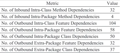
Table 1. Complexity of dependency graph
The dependency graph of the analyzed classes contains two strongly connected components; therefore, the hierarchical structure of the graph is not trivial and can not be reduced to a uniquely defined perfect structure. The graph contains only one weakly connected component; therefore, features can not be separated easily. The complexity of the dependency graph extracted from these 4 classes is summarized in Table 1.
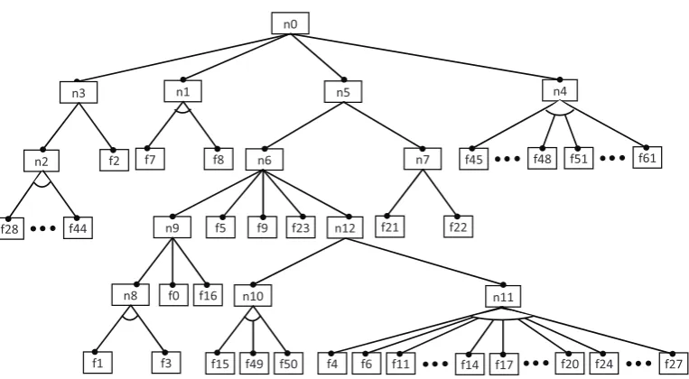
The features were clustered using the Cobweb
algorithm and the obtained feature tree was converted into the feature model. The results of feature model extraction using the methodology described in sub-section 2.5 are presented formally (textually) in Fig. 4 (as Prolog rules) and graphically in Fig. 5 (as a Feature Diagram).
n0: all(n1,n3,n5,n4). n1:more_of(f7,f8).
n2:more_of(f43,f34,f42,f33,f32,f44,f31,f30, f41,f40,f39,f29,f38,f37,f28,f36,f35). n3:more_of(f2,n2).
n4:more_of(f59,f45,f57,f58,f60,f51,f61,f52, f47,f55,f46,f56,f53,f48,f54). n5:all(n7,n6).
n6:all(n9,f9,f23,n12,f5). n7:more_of(f21,f22). n8:more_of(f1,f3). n9:all(n8,f16,f0). n10:more_of(f15,f50,f49).
n11:more_of(f6,f12,f11,f20,f10,f25,f24,f27, f14,f26,f13,f19,f18,f17,f4).
n12:all(n10,n11).
Figure 4. Prolog rules representing the extracted feature model
Figure 5. Graphical representation (feature diagram) of the extracted feature model of a subset of Buffer classes
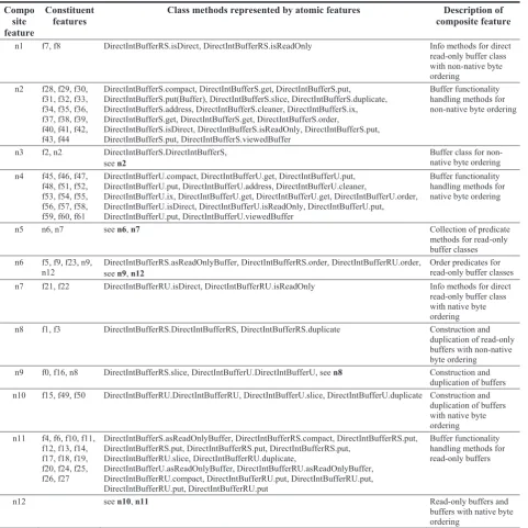
The relation of the features in the extracted feature model to the class methods are summarized in Table 2. Analysing the results presented in Table 2, we can note that the proposed method has correctly identified and located composite features and separated them from other composite features representing buffer construction aspects (class constructors, duplication methods), predicate methods, functionality handling methods, and made a clear distinction between buffer classes with native (DirectIntBufferS) and non-native (DirectIntBufferU) byte ordering as well as read only
buffer classes (DirectIntBufferRS, DirectIntBufferRU).
Table 3. Metrics of a derived feature model
Metric Value
No. of features 73
No. of solitary features 61
No. of variant points 12
Cognitive complexity 17
Finally, in Table 3 we present some of the complexity metrics [42] of the derived executable feature model in Prolog (Fig. 4) computed automatically using the SWI-Prolog engine (http://www.swi-prolog.org/).
4. Conclusions and further work
In this paper, we have analysed the problem of reverse engineering source code to feature models. We presented a framework for the automated derivation of feature models from the existing Java programs, and proposed a method for feature model generation based on feature dependency extraction and clustering. The method is fully automatic and allows for generation of feature model descriptions in Feature Description Language (FDL) as well as Prolog rules, which can be further used for feature model validation, computation of product configuration and evaluation of feature model properties. The method could be used for: 1) partial configuration of software systems, when a
f7 f8 n1
f28 n2
f44
f51 n4
f61 f45 f48
n0
f2 n3
f21 f22 n7 n5
f14 f17 n11
f20
f11 f24
f6
f4 f27
f1 f3 n8 f0 f16
n9
f49 f15 f50
n10
n12 f9
Table 2. Summary of composite features in Buffer feature model
Compo site feature
Constituent features
Class methods represented by atomic features Description of composite feature
n1 f7, f8 DirectIntBufferRS.isDirect, DirectIntBufferRS.isReadOnly Info methods for direct
read-only buffer class with non-native byte ordering
n2 f28, f29, f30, f31, f32, f33, f34, f35, f36, f37, f38, f39, f40, f41, f42, f43, f44
DirectIntBufferS.compact, DirectIntBufferS.get, DirectIntBufferS.put, DirectIntBufferS.put(Buffer), DirectIntBufferS.slice, DirectIntBufferS.duplicate, DirectIntBufferS.address, DirectIntBufferS.cleaner, DirectIntBufferS.ix, DirectIntBufferS.get, DirectIntBufferS.get, DirectIntBufferS.order,
DirectIntBufferS.isDirect, DirectIntBufferS.isReadOnly, DirectIntBufferS.put, DirectIntBufferS.put, DirectIntBufferS.viewedBuffer
Buffer functionality handling methods for non-native byte ordering
n3 f2, n2 DirectIntBufferS.DirectIntBufferS,
see n2
Buffer class for non-native byte ordering n4 f45, f46, f47,
f48, f51, f52, f53, f54, f55, f56, f57, f58, f59, f60, f61
DirectIntBufferU.compact, DirectIntBufferU.get, DirectIntBufferU.put, DirectIntBufferU.put, DirectIntBufferU.address, DirectIntBufferU.cleaner,
DirectIntBufferU.ix, DirectIntBufferU.get, DirectIntBufferU.get, DirectIntBufferU.order, DirectIntBufferU.isDirect, DirectIntBufferU.isReadOnly, DirectIntBufferU.put, DirectIntBufferU.put, DirectIntBufferU.viewedBuffer
Buffer functionality handling methods for native byte ordering
n5 n6, n7 see n6, n7 Collection of predicate
methods for read-only buffer classes n6 f5, f9, f23, n9,
n12
DirectIntBufferRS.asReadOnlyBuffer, DirectIntBufferRS.order, DirectIntBufferRU.order, see n9, n12
Order predicates for read-only buffer classes
n7 f21, f22 DirectIntBufferRU.isDirect, DirectIntBufferRU.isReadOnly Info methods for direct
read-only buffer class with native byte ordering
n8 f1, f3 DirectIntBufferRS.DirectIntBufferRS, DirectIntBufferRS.duplicate Construction and
duplication of read-only buffers with non-native byte ordering
n9 f0, f16, n8 DirectIntBufferRS.slice, DirectIntBufferU.DirectIntBufferU, see n8 Construction and
duplication of buffers n10 f15, f49, f50 DirectIntBufferRU.DirectIntBufferRU, DirectIntBufferU.slice, DirectIntBufferU.duplicate Construction and
duplication of buffers with native byte ordering n11 f4, f6, f10, f11,
f12, f13, f14, f17, f18, f19, f20, f24, f25, f26, f27
DirectIntBufferS.asReadOnlyBuffer, DirectIntBufferRS.compact, DirectIntBufferRS.put, DirectIntBufferRS.put, DirectIntBufferRS.put, DirectIntBufferRS.put,
DirectIntBufferRU.slice, DirectIntBufferRU.duplicate,
DirectIntBufferU.asReadOnlyBuffer, DirectIntBufferRU.asReadOnlyBuffer, DirectIntBufferRU.compact, DirectIntBufferRU.put, DirectIntBufferRU.put, DirectIntBufferRU.put, DirectIntBufferRU.put
Buffer functionality handling methods for read-only buffers
n12 see n10, n11 Read-only buffers and
buffers with native byte ordering
leaner version of a system is derived from a richer system; 2) finding feature patterns; 3) automatic assembly of new system feature models from parts of existing system feature models; 4) development of feature model libraries.
Future work will deal with the following problems: 1) Performance. The computational complexity of
the proposed method is high (i.e., On3 as
determined by the Floyd’s algorithm). The perfor-mance must be improved, e.g., using approximate shortest path algorithms [43], to deal with large-scale real-world programs.
2) Empirical research of alternative clustering algorithms. Clustering is the critical part of the
process of features location, because feature model has the same structure as clustering dendrogram. However, different clustering algorithms may produce different dendrograms on a graph of non-trivial complexity. This means that more than one clustering technique can be considered for comparative analysis and more complex case study organized to show and compare results of different clustering approaches with associated interpretations (descriptions of composite features) to internal nodes of computed dendrograms.
3) Determination of feature model constraints.
Currently, only a subset of Feature Diagram notation
is supported, which does not include the requires
constraints usually have a very large product space, which has to be reduced at a later modelling stage. Identification of constraints would greatly reduce the size of product space thus decreasing the need for further domain analysis. However, the extraction of constraints in a feature models will require additional analysis of source code and software dependencies.
4) Integration. The implementation of the method will be integrated into an existing feature modelling environment to allow for combining feature-based design methods with reverse engineering capabilities.
References
[1] Y. Coppel, G. Candea. Deprogramming Large Software Systems. Proc. of the Fourth Workshop on Hot Topics in Systems Dependability, HotDep 2008,
San Diego, CA, USA, December 7, 2008. USENIX Association, 2008, pp. 3.
[2] N. Sangal, E. Jordan, V. Sinha, D.Jackson. Using dependency models to manage complex software architecture. SIGPLAN Notices 40, 10, 167-176. (2005), http://dx.doi.org/10.1145/1103845.1094824. [3] J. L.Pfaltz. Using Concept Lattices to Uncover
Causal Dependencies in Software. In R. Missaoui, J. Schmid (Eds.): Formal Concept Analysis.Proceedings of 4th International Conference, ICFCA 2006,
Dresden, Germany. LNCS 3874, pp. 233-247. Springer (2006).
[4] H. J. Basten, P. Klint. DeFacto: Language-Parametric Fact Extraction from Source Code. Proc. of the 1st Int. Conf. of Software Language Engineering (SLE 2008),
Toulouse, France, September 2008. LNCS 5452, pp. 265-284. Springer-Verlag (2008)
[5] S. Ducasse, M. Rieger, S.Demeyer. A language inde-pendent approach for detecting duplicated code. In:
Proceedings of the International Conference on Software Maintenance (ICSM’99), 109–118 (1999), http://dx.doi.org/10.1109/ICSM.1999.792593.
[6] R. Ferenc, A. Beszédes, L. J. Fülöp, J.Lele. Design Pattern Mining Enhanced by Machine Learning. Proc. of 21st IEEE Int. Conf. on Software Maintenance (ICSM 2005), Budapest, Hungary, 295-304 (2005), http://dx.doi.org/10.1109/ICSM.2005.40.
[7] G. Guo, J. Atlee, R.Kazman. A software architecture reconstruction method. Proc. of the First Working IFIP Conf. on Software Architecture, San Antonio, TX, USA, 15-34 (1999).
[8] D. Bojic, D.Velasevic. A use-case driven method of architecture recovery for program understanding and reuse reengineering. Proc. of the 4th European Conf. On Software Maintenance and Reengineering, Zurich, Switzerland, 23-31 (2000).
[9] P. Bengtsson, J.Bosch. Scenario-based software architecture reengineering. Proc. of 5th Int. Conf. on Software Reuse, 2-5 Jun 1998, 308–317 (1998).
[10] C. Riva, J. V.Rodriguez. Combining static and dynamic views for architecture reconstruction. In:
Proceedings of Sixth European Conference on Software Maintenance and Reengineering, pp. 47-55 (2002), http://dx.doi.org/10.1109/CSMR.2002.995789. [11] K. Bontcheva, M.Sabou. Learning Ontologies from
Software Artifacts: Exploring and Combining Multiple Sources. Proc. of Workshop on Semantic Web Enabled
Software Engineering (SWESE), 2006. Available at: http://gate.ac.uk/sale/iswc06/tao.pdf.
[12] V. Štuikys, R. Damaševiius, A. Targamadz. A Model-Driven View to Meta-Program Development Process. Information Technology and Control, 39(2), (2010), pp. 89 – 99.
[13] E. J. Chikofsky, J. H.Cross II. Reverse Engineering and Design Recovery: A Taxonomy. IEEE Software,
7(1), 13–17(1990), http://dx.doi.org/10.1109/52.43044. [14] S. She, R. Lotufo, T. Berger, A. Wasowski, K. Czarnecki. Reverse Engineering Feature Models.
Proc. of 33rd Int. Conf. on Software Engineering, Waikiki, Honolulu, Hawaii, USA, 461-470 (2008). [15] W. Zhang, S. Jarzabek, N. Loughran, A.Rashid.
Reengineering a PC-Based System into the Mobile Device Product Line. In: Proceedings of 6th International Workshop on Principles of Software Evolution (IWPSE 2003), Helsinki, Finland, 149-160, http://dx.doi.org/10.1109/IWPSE.2003.1231222. [16] V.Vrani . Multi-Paradigm Design with Feature
Modeling. In: Computer Science and Information Systems, Vol. 2, No. 1, 2005, pp. 79-102, http://dx.doi.org/10.2298/CSIS0501079V.
[17] K. C. Kang, J. Lee, P.Donohoe. Feature-Oriented Project Line Engineering. IEEE Software 19, 4 (2002), 58-65, http://dx.doi.org/10.1109/MS.2002.1020288. [18] M. A. Laguna, J. M. Marques, G.Rodrguez-Cano.
Feature Diagram Formalization Based on Directed Hypergraphs. Computer Science and Information Systems, Vol. 8, No. 3, 2011, pp. 611-633, http://dx.doi.org/10.2298/CSIS100804016L.
[19] D. Poshyvanyk, Y. Gael-Guéhéneuc, A. Marcus, G. Antoniol, V.Rajlich. Feature Location using Probabilistic Ranking of Methods based on Execution Scenarios and Information Retrieval. IEEE Trans. on Software Engineering, 33(6), 420-432 (2007), http://dx.doi.org/10.1109/TSE.2007.1016.
[20] I. T. Bowman, M. W. Godfrey, R. C. Holt. Extrac-ting Source Models from Java Programs: Parse, Disassemble, or Profile? In: ACM SIGPLAN Workshop on Program Analysis for Software Tools and Engineering, Toulouse, France (1999). Unpublished
paper available at: http://plg.uwaterloo.ca/~migod/papers/1999/paste99.pd
f.
[21] G. Snelting, F.Tip. Reengineering Class Hierarchies Using Concept Analysis. Proc. of ACM SIGSOFT 6th Int. Symp. on Foundations of Software Engineering,
FSE-6, 99–110, Lake Buena Vista, FL (1998).
[22] N. Wilde, M. Buckellew, H. Page, V. Rajlich, L. Pounds. A Comparison of Methods for Locating Features in Legacy Software. In: Journal of Systems and Software, Vol. 65, No. 2, 105-114 (2003), http://dx.doi.org/10.1016/S0164-1212(02)00052-3. [23] S. Simmons, D. Edwards, N. Wilde, J. Homan,
M.Groble. Industrial tools for the feature location problem: an exploratory study. J. of Software Maintenance: Research and Practice, 18(6) 457-474 (2006), http://dx.doi.org/10.1002/smr.338.
[24] A. Marcus, V. Rajlich, J. Buchta, M. Petrenko, A.Sergeyev. Static Techniques for Concept Location in Object-Oriented Code. Proc. 13th IEEE Int. Workshop on Program Comprehension, 33-42 (2005), http://dx.doi.org/10.1109/WPC.2005.33.
Communications of the ACM, 37(5), 72-83 (1994), http://dx.doi.org/10.1145/175290.175300.
[26] A. Kuhn, S. Ducasse, T.Gorba. Semantic clustering: Identifying topics in source code. In: Information and Software Technology, Vol.49, No.3, 230-243 (2007), http://dx.doi.org/10.1016/j.infsof.2006.10.017.
[27] L. Ablonskis, L. Nemurait. Discovery of Model Implementation Patterns in Source Code. Information Technology and Control, 39(1), 68 - 76 (2010). [28] L. Ablonskis, L. Nemurait. Discovery of Complex
Model Implementation Patterns in Source Code.
Information Technology and Control, 39(4), 291-300 (2010).
[29] W. Zhao, L. Zhang, Y. Liu, J. Sun, F. Yang.
SNIAFL: Towards a Static non-interactive Approach to Feature Location. ACM Trans. on Software Engineering and Methodologies, 15(2), 195-226 (2006), http://dx.doi.org/10.1145/1131421.1131424. [30] C. Mao. Structure visualization and analysis for
software dependence network. IEEE Int. Conf. on Granular Computing (GrC), 439-444 (2011).
[31] Y. Yang, X. Peng, W.Zhao. Domain Feature Model Recovery from Multiple Applications Using Data Access Semantics and Formal Concept Analysis. Proc. of 16th Working Conf. on Reverse Engineering, WCRE 2009, Lille, France, 215-224 (2009).
[32] D. Poshyvanyk, A. Marcus. Combining Formal Concept Analysis with Information Retrieval for Concept Location in Source Code. Proc. of the 15th IEEE Int. Conf. on Program Comprehension (ICPC '07), Washington, DC, USA, 37-48 (2007), http://dx.doi.org/10.1109/ICPC.2007.13.
[33] M. Salah, S. Mancoridis. A hierarchy of dynamic software views: from object-interactions to feature interactions. Proc. 20th IEEE Int. Conf. on Software Maintenance, Chicago, IL, USA, 72-81 (2004), http://dx.doi.org/10.1109/ICSM.2004.1357792.
[34] K.Kittilä. Analysing and Managing Software Dependencies with a Dependency Structure Matrix Tool. Master’s Thesis, University of Oulu (2008). Available at: http://web.sysart.fi/dtangler/_media/kitti la_dsmtoolthesis.pdf.
[35] L. A. Barowski, J. H. Cross II. Extraction and Use of Class Dependency Information for Java. In: Proc. of 9th Working Conf. on Reverse Engineering (WCRE 2002), Richmond, VA, USA, 309-318 (2002), http://dx.doi.org/10.1109/WCRE.2002.1173088. [36] D. H.Fisher. Knowledge acquisition via incremental
conceptual clustering. Machine Learning 2: 139–172 (1987), http://dx.doi.org/10.1007/BF00114265. [37] A. van Deursen, P.Klint. Domain-Specific Language
Design Requires Feature Descriptions. Journal of Computing and Information Technology, 10(1), 1-17 (2002), http://dx.doi.org/10.2498/cit.2002.01.01.
[38] P. Paškeviius, M. Bindokas, A. Kasperaviius, R. Damaševiius. Executable models and model transformations: a framework for research. Proc. of 17th Int. Conf. on Information and Software Technologies, IT 2011, 76-83 (2011).
[39] S. Jarzabek, S. Li. Unifying clones with a generative programming technique: a case study. In: Journal of Software Maintenance and Evolution: Research and Practice, Vol. 18, No. 4, pp. 267-292 (2006) http://dx.doi.org/10.1002/smr.333.
[40] D. C. Rajapakse, A. H. Basit, S. Jarzabek. An Empirical Study on Limits of Clone Unification Using Generics. Proc. 17th Int. Conference on Software Engineering and Knowledge Engineering, SEKE'05, Taipei, Taiwan, 109-114 (2005).
[41] R. Damaševiius. Analysis of Components for Generalization using Multidimensional Scaling.
Fundamenta Informaticae, 91(3-4), 507-522, (2009). [42] V. Štuikys, R. Damaševiius. Measuring complexity
of domain models represented by feature diagrams.
Information Technology and Control, 38(3), 179-187, (2009).
[43] L. Roditty, U. Zwick. Dynamic approximate all-pairs shortest paths in undirected graphs. In: Proceedings of 45th Annual IEEE Symposium on Foundations of Computer Science, pp. 499-508 (2004), http://dx.doi.org/10.1109/FOCS.2004.22.