229
Copyright © 2018. IJEMR. All Rights Reserved.
Volume-8, Issue-3, June 2018
International Journal of Engineering and Management Research
Page Number: 229-234
DOI:
doi.org/10.31033/ijemr.8.3.30
Thermal Efficiency of Combined Cycle Power Plant
R. Rajesh1 and Dr. P.S. Kishore2
1M.Tech student, Thermal Engineering., Department of Mechanical Engineering, Andhra University, Visakhapatnam, Andhra
Pradesh, INDIA
2Professor, Department of Mechanical Engineering, Andhra University, Visakhapatnam, Andhra Pradesh, INDIA
1Corresponding Author: [email protected]
ABSTRACT
Now a day’s power generation is most important for every country. This power is generated by some thermal cycles. But single cycle cannot be attain complete power requirements and its efficiency also very low so that to fulfill this requirements to combine two or more cycles in a single power plant then we can increase the efficiency of the power plant. Its increased efficiency is more than that of if the plant operated on single cycle. In which we are using two different cycles and these two cycles are operated by means of different working mediums. These type of power plants we can called them like combined cycle power plants. In combined cycle power plants above cycle is known as topping cycle and below cycle is known as bottoming cycle. The above cycle generally brayton cycle which uses air as a working medium. When the power generation was completed the exhaust gas will passes in to the waste heat recovery boiler. Another cycle also involved in bottoming cycle. This cycle works on the basis on rankine cycle. In which steam is used as working medium. The main component in bottoming cycle is waste heat recovery boiler. It will receive exhaust heat from the gas turbine and converts water in to steam. The steam used for generating power by expansion on steam turbine. Combined cycle power plants are mostly used in commercial power plants.
In this paper we are analyzing one practical combined cycle power plant. In practical conditions due to some losses it can not be generates complete power. So that we are invistigated why it is not give that much of power and the effect of various operating parameters such as maximum temperature and pressure of rankine cycle, gas turbine inlet temperature and pressure ratio of Brayton cycle on the net output work and thermal efficiency of the combine cycle power plant.
The outcome of this work can be utilized in order to facilitate the design of a combined cycle with higher efficiency and output work. Mathematical calculations and simple graphs in ms excel, and auto cad has been carried out to study the effects and influences of the above mentioned parameters on the efficiency and work output.
Keywords-- Brayton Cycle, Rankine Cycle, Heat Supplied Work Output and Efficiency
I.
INTRODUCTION
Combined cycle power plants used for generate electricity and also cogeneration. Generally combined cycles are made up of two cycles. One is gas turbine cycle and another one is Rankine cycle. This gas turbine cycle may be simple gas turbine or inter cooling or reheating or regeneration gas turbine cycle and Rankine cycle maybe simple Rankine cycle or reheat or regeneration Rankine cycle. According to the application and power generation capacities, different combinations are used. Generally combined cycle efficiency can increase by number of ways.(i) decreasing the inlet temperature so that the gas turbine efficiency of combined cycle gas turbine increases (ii) increasing the compression ratio then combined cycle power plant efficiency will increases (iii) increasing the combustion temperature in combustion chamber so that plant efficiency increases (iv) increasing the boiler temperature and pressure then combined cycle power plant efficiency increases (v) decreasing the condenser pressure in Rankine cycle (combined cycle power plant.) efficiency increases.
230
Copyright © 2018. IJEMR. All Rights Reserved.
[3] In their paper explained about combined cycle (CC) and combined heat and power (CHP) process for energy generation and capacities of different power plants at different loading conditions. Alhazmy and Najjar [4] in their paper they provided an information about different power generation cycles i.e.., Brayton cycle, Rankine cycle, and combined cycles, and its practical applications and also they discussed the effect on combined cycle efficiency by changing the parameters like heat supplied to the gas turbine, feed water heater temperature, and boiler pressure and temperature of the boiler and also provided an information for introduction to combined cycle power plants and gave detailed information of different combined cycle power plants that are already operated in different countries. Kishore et al. [5] have given the information above effectiveness of convective condensation of steam in a horizontal tube with twisted tube inserts. Rahman et al. [6] in their paper said that in the present days every thermal power plant was designed to generate more power but for power generation there should be place for equipment and auxiliary equipments. This auxiliary equipment consumes more power. Hence they gave their different methods to reduce power consumption of auxiliary equipments has to increase the efficiency of the
combined cycle power plant. Xiaojun et al. [7] in their
paper discussed the operation of organic Rankine cycle and organic fuels that are mostly used. The effect on efficiency, work output and waste heat recovery in a boiler is increased. Kishore et al. [8] in their paper overviewed on the method to predict turbulent convective heat transfer coefficient of condensation of steam–air mixture in a horizontal tube. Kaushika et al. [9] In their paper explained importance of power generation. They said that every thermal power plant consists of different machinery. In that auxiliary equipment plays major role. These equipments will consume part of the work from the total power generated. They gave information how to reduce the power consumption of auxiliary equipment and provide different methods to improve the efficiency of the plant. Khaliq and Kaushik et al. [10] in their paper gave information about individual gas turbine power plants and combined cycle power plants they also gave the applications of gas turbines in jet propulsions and power generation in industries. Thamir et al. [11] in their paper provided information about in topping cycle of the combined gas turbine power plant. They said that perfect air inlet temperature in compressor; perfect air fuel ratio in combustion chamber and maintaining sufficient pressure ratio the efficiency of the entire plant will increase. Rai et al. [12] in their paper studied the performance evaluation of expansion turbine gas cooler is a steel plant. Palla [13] in his paper he explained about different conderations to make gas turbines with different combinations. R.Rajesh [14] estimated the Evaluation of work output and efficiencies of combined cycle gas turbine power plant by changing different parameters in topping cycle and
bottoming cycles. In every condition the work output and efficiencies are increased.
II. DESCRIPTION AND WORKING OF
CGT
The combined cycle power plant is a combination of simple gas turbine plant which is treated to be a topping cycle and ranking cycle which is treated to be a bottoming cycle. The combined cycle plant layout Fig 3.1 is given below.The practical combined cycle power plant. It is having generally two cycles, primary cycle is gas turbine cycle is and secondary cycle is Rankine cycle but power plant is designed for maximum power generation but due to some losses its overall work output is very low.In this work improvement of the total work output of the power plant is designed by changing the gas turbine heat supplied. So that increasing the heat supplied to the gas turbine this will increase the exhaust gas temperatures so that the heat supplied to the steam boiler will increase. When heat supplied to the steam turbine increases the pressure and temperature of steam also increases by this operation and the better power output from the gas turbine and steam turbine are possible. It helps to finally increase the work output of the combined cycle plant and also increases the efficiency of the practical combined cycle power plant. In this combined cycle power plant first operation is gas turbine operation in which when the combustion takes place in the combustion chamber it will expand in the gas turbine so that power will be obtained from this operation. Second operation is when exhaust gases expands in the gas turbine it enters into the waste heat recovery boiler so that the water which is presented in the boiler gets converted into the steam. This high pressure and temperature steam expand in the steam turbine so that
the power will be obtained from the steam turbine.
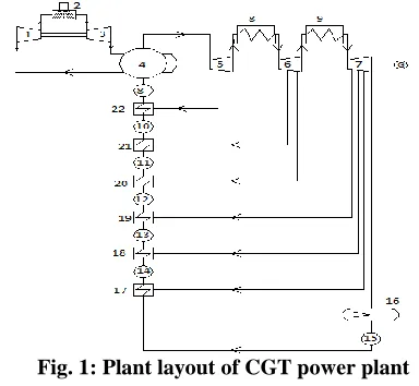
Fig. 1: Plant layout of CGT power plant
Components:
1. Gas turbine compressor
231
Copyright © 2018. IJEMR. All Rights Reserved.
3. Gas turbine
4. Steam boiler
5, 6, 7. Steam turbines
8, 9. Reheaters
22, 21, 20,19,18,17. Feed water heaters
16. Steam condenser
8,10, 11,12,13,14,15. Pumps
(A)Topping Cycle of a Combined Cycle Power Plant
The topping cycle power plant consists of axial flow compressor, combustion chamber, and an axial flow reaction turbine, the atmospheric air is first sent in compressor, where it is compressed to 8bar and with rise in temperature. The compressed air is sent in combustion chamber. The natural gas with more amount of methane (70%), ethane (30%) is injected by means of six nozzles inside the combustion chamber. The fuel is burnt and exhaust gases are generated. These gases will enter in to the axial flow reaction gas turbine generating power output. The exhaust gases after power generation goes in to a waste heat recovery boiler in the bottom cycle. In above figure circuit 1-2 represents the gas turbine unit.
(B)Bottoming Cycle of a Combined Cycle Power Plant
The Bottoming cycle of a combined cycle power plant consists of waste heat recovery boiler, three axial flow steam turbines, two reheaters, one supplementary heater, six feed water heaters, seven feed pumps, one condensation tank and one steam condenser. The exhaust gases coming from turbine of a topping cycle is use to heat water in a waste heat recovery boiler. After supplementary firing in bituminous coal fired furnace. The water is heated up to the required temperature and sent in to the first turbine. After expansion in turbine some steam is taken out and fed to feed water heater. The remaining steam is again meat to pass first reheater and to second turbine at two outlets the exhaust steam is taken away and fed to two feed water heaters. The steam is taken by second turbine reheated by second reheater and fed to third turbine after the power output generated from third turbine four outlets are taken away and they are made to go to three feed water heaters and last to a condenser and these are taken at different pressure outlets. The steams collected in feed water heaters are again fed to waste heat recovery boiler. The work output of a combined cycle power plant is the summation of work outputs of gas turbine power output and work output of a ranking cycle power plant. In above figure circuit 4-22 represents the steam turbine with reheating and regenerating unit.
III.
ANALYSIS ON CGT
1. Gas turbine cycle:
Process 1-2: (isentropic compression)
1. = (1)
Where,
= Inlet temperature of gas turbine (0C).
= Output temperature of the compressor
(0C).
= Inlet air pressure of the gas turbine
compressor (bar).
= Output let air pressure of the gas turbine
compressor (bar).
= Specific heat ratio.
Process 3-4: (isentropic expansion)
2. = (2)
Where,
= Input temperature of the gas turbine
(0C).
= Output temperature of the exhaust gases
(0C).
= Output let gases pressure of the gas
turbine combustion chamber (bar).
= Output let exhaust gases pressure of the
gas turbine (bar).
3. Work extraction from the gas turbine:
Wgt = macp (Tc – Td) (3)
Where,
= Mass of air (kg/sec).
= Specific heat of natural gas at constant
pressure (kJ/kg K).
4. Work of the gas turbine compressor:
Wc = macp (Tb – Ta) (4)
5. Net work output from gas turbine cycle:
Wgt net = Wgt – Wgt net (5)
Wgt net = mcp (Tc – Td) – mcp (Tb – Ta)
6. Heat supplied to the gas turbine:
Qs = mcp (Tc – Tb) (6)
7. Efficiency of gas turbine:
(ηgt) =
(ηgt) = 1 (7)
Where,
= Pressure ratio
2. Steam turbine cycle:
Corresponding enthalpies and entropies are finding with help of boiler and feed water heater pressures in Moeller chart and steam tables.
8. Entropy at condenser inlet
= (8)
Where,
= Entropy at condenser inlet (kJ/kg K)
= Entropy at fluid state condenser inlet
232
Copyright © 2018. IJEMR. All Rights Reserved.
= Entropy at semi fluid and gaseous at
state condenser inlet (kJ/kg K)
= Dryness fraction at condenser inlet
9. Dryness fraction at condenser inlet:
= (9)
10. Enthalpy at condenser inlet:
= (10)
Where,
= Enthalpy at inlet of the steam condenser
(kJ/kg)
= Enthalpy at fluid state condenser inlet
(kJ/kg K)
= Enthalpy at semi fluid and gaseous at
state condenser inlet (kJ/kg K) 11. Work done by the steam turbine:
(11) Where,
= Enthalpy at inlet of the first steam
turbine, (kJ/kg)
h2 = Enthalpy at outlet of the first steam
turbine, (kJ/kg)
= Enthalpy at inlet of the second steam
turbine, (kJ/kg)
h5 = Enthalpy at outlet of the second steam
turbine, (kJ/kg)
= Enthalpy at inlet of the third steam
turbine, (kJ/kg)
h7 = Enthalpy at outlet of the third steam
turbine, (kJ/kg)
= Enthalpy at inlet of the sixth feed water
heater (kJ/kg)
= Enthalpy at inlet of the second feed
water heater (kJ/kg)
= Enthalpy at inlet of the first feed water
heater (kJ/kg)
= Enthalpy at inlet of the steam condenser
(kJ/kg)
12. Pump work of steam power plant:
Where,
= Enthalpy at inlet of the first feed pump,
(kJ/kg)
h12 = Enthalpy at outlet of the first feed pump,
(kJ/kg)
= Enthalpy at inlet of the second feed
pump, (kJ/kg)
h14 = Enthalpy at outlet of the second feed
pump, (kJ/kg)
= Enthalpy at inlet of the third feed pump,
(kJ/kg)
h16 = Enthalpy at outlet of the third feed pump,
(kJ/kg)
= Enthalpy at inlet of the fourth feed
pump, (kJ/kg)
h18 = Enthalpy at outlet of the fourth feed
pump, (kJ/kg)
= Enthalpy at inlet of the fifth feed pump,
(kJ/kg)
h20 = Enthalpy at outlet of the fifth feed pump,
(kJ/kg)
= Enthalpy at inlet of the sixth feed pump,
(kJ/kg)
h22 = Enthalpy at outlet of the sixth feed
pump, (kJ/kg)
= Enthalpy at inlet of the seventh feed
pump, (kJ/kg)
h24 = Enthalpy at outlet of the seventh feed
pump, (kJ/kg)
13. Total work done by the steam power plant = (work of turbine – work of the pump) x mass of steam supplied
Wst net = (12)
Where,
= Mass of the steam supplied (kg/sec) 14. Total heat supplied to steam power plant:
) (13)
Efficiency of the steam power plant:
(ηsteam) =
3. Combined cycle:
15. Total work done of combined cycle gas turbine power plant:
(14)
Where,
= work of the gas turbine = work of the steam turbine
16. Total heat supplied to the combined cycle gas turbine power plant:
(15)
Where,
Heat supplied to the gas turbine
Heat supplied to the steam turbine
17. Total efficiencyof combined cycle gas turbine power
plant:
(16)
233
Copyright © 2018. IJEMR. All Rights Reserved.
Fig. 6: Variation of rate of inlet temperatures (K) withgas turbine heat supplied (Q)
The above Fig. (6) Shows the variation of inlet temperatures with heat supplied in gas turbine (Q). Temperature increase is more in Brayton cycle (topping cycle) compared to Rankine cycle (bottoming cycle). As the heat supplied in gas turbine the inlet temperature of it increase and as well as steam turbine inlet temperature increases. At a particular point of heat supplied it was found that the inlet temperature of gas turbine is more than inlet temperature of steam turbine.
Fig. 7: Variation of boiler pressure (P) with gas turbine heat supplied (Q) The above Fig. (7) Gives a variation
of boiler pressure (P) with gas turbine heat supplied (Q). It is noted that as gas turbine heat supplied increases the boiler pressure in bottoming cycle
gradually increases gives more heat.
Fig. 8: Variation of rate of Wnet with gas turbine heat supplied (Q)
The above Fig. (8) shows the variation of net work done with gas turbine heat supplied (Q). It is found that the work output of combined cycle power plant is more than that of steam power cycle and gas turbine cycle because combined cycle power plant work done is the sum of the work done of Rankine cycle power plant and gas turbine power plant. In gas turbine power plant it consumes more work in compressor so it won’t be able to produce more work output. In Rankine cycle, pump consumes very less work so that it produces somewhat high power output compared to the gas turbine.
Fig. 9: Variation of efficiency (η) with gas turbine heat supplied (Q)
234
Copyright © 2018. IJEMR. All Rights Reserved.
of Ranking cycle is more than efficiency of gas turbine cycle.
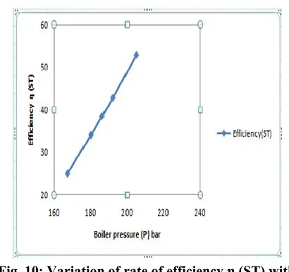
Fig. 10: Variation of rate of efficiency η (ST) with boiler pressure (P) bar
The above Fig. (10) shows the variation of efficiency η (ST) with boiler pressure (P) bar when pressure of steam boiler increases the efficiency of steam power plant increases.
V.
CONCLUSIONS
The following conclusions are arrived when the input parameters of a combined cycle power plant is taken. Varying heat input to the gas turbine from 475 MW to 550 MW and maintaining compression ratio is 8.
1. Input temperature of the gas turbine varies from 876.528
K to 1026.658 K an increase of 41.62%. Input temperature of the steam turbine varies from 781.23 K to 858.36 K an increase of 35.82%.
2. Boiler pressure of the plant varies from 167 bar to 205
bar an increase of 33.58%.
3. Net work done by the gas turbine varies from 91.65 MW
to 166.729 MW an increase of 29.36%. Net work done by the steam turbine varies from 643.606 MW to 692.848 MW an increase of 35.86%. Net work done by the combined cycle varies from 752.864 MW to 843.843.75 MW an increase of 39.64%.
4. The efficiency of the gas turbine varies from 19.86% to
44.86% an increase of 23.64%. The efficiency of the steam turbine varies from 26.179% to 51.62% an increase of 29.58%. The efficiency of the combined cycle varies from 30.624% to 55.91% an increase of 35.69%.
5. The boiler input pressure of the plant varies from 167
bar to 205 bar an increase of 33.58%. The efficiency of the steam turbine varies from 26.179% to 51.62% an increase of 29.58%.
6. The input parameters of gas turbine and steam turbine
such as inlet temperatures, input pressures increases, output parameters like work output of the gas turbine,
steam turbine and combined cycle gas turbine are found to increase respectively.
ACKNOWLEDGMENT
We, authors express gratitude to all the anonymous reviewers for their affirmative annotations among our paper. Thanks to every reviewer for reviewing our paper and give valuable suggestions.
REFERENCES
[1] Thamir K. Ibrahim & M.M. Rahman. (2012). Effect of compression ratio on performance of combined cycle gas
turbine. International Journal of Energy Engineering, 2(1),
9-14.
[2] Ashley De Sa & Sarim Al Zubaidy. (2011). Gas turbine
performance at varying ambient temperature. Applied
Thermal Engineering, 31, 2735–2739.
[3] Carniere H., Willocx A., Dick E., & Paepe M De., (2006). Raising cycle efficiency by inter cooling in air
cooled gas turbine. Applied Thermal Engineering, 26(16),
1780–1787.
[4] AlHazmy M.M. & Najjar Y.S.H. (2004). Augmentation
of gas turbine performance using air coolers. Applied
Thermal Engineering, 24(2-3), 415-429.
[5] P.k. Sarma, K.Hari Babu , T.Subrahmanyam,
V.Dharma Rao, & P.S.Kishore. (2006, March).
Augmentation of convective condensation of steam in a
horizontal tube with twisted tape inserts. (World scientific
and engineering academy and society) Transations on
Heat and Mass Transfer, 1(3), 222-228.
[6] Thamir K. Ibrahim & Rahman M.M. (2012). Thermal impact of operating conditions on the performance of a
combined cycle gas turbine. Journal of Applied Research
and Technology, 10(4), 567–577.
[7] Firdaus B., Takanobu Y., Kimio N., & Soe N. (2011). Effect of ambient temperature on the performance of micro gas turbine with cogeneration system in cold region.
Applied Thermal Engineering, 31, 1058–1067.
[8] P.K.Sarma, C.P.Ramanayanan, K.V.Sharma,
P.S.Kishore, & V.Dharma Rao. (2009, June). A method to predict turbulent convective heat transfer coefficients of condensation of steam-air mixture in a horizontal tube.
International Journal of Heat and Technology, 27(1),
45-56.
[9] Kaushika S.C., Reddya V.S., & Tyagi S.K. (2011). Energy and exergy analyses of thermal power plants: A
review. Renewable Sustainable Energy Review, 15, 1857–
1872.
[10] Khaliq A. & Kaushik S.C. (2004). Thermodynamic performance evaluation of combustion gas turbine
cogeneration system with reheat. Applied Thermal