Performance Analysis of the Positioning of Superconducting Fault Current
Limiters for the Smart Grid Application Using MATLAB Simulink
Pravin S. Chaudhari, Prof. Prabodh kumar Khampariya Sri Satya Sai Institute of Science and Technology, Sehore, India
Abstract - By virtue of increasing amount of distributed generation due to ever-increasing the demand and consumption of electric power widely, the chances of occurrence of any kind of fault or abnormal condition are very common, due which it crosses the rated capacity of the existing circuit breakers. Among the countermeasures to solve the short-circuit problem in a power distribution system considering the increase of the DG, the superconducting fault current limiter (SFCL) has been noticed as one of the promising devices. It has the capability to limit fault current within first cycle, can suppress the unanticipated short-circuit currents in utility distribution and transmission networks, so that the underrated switchgears can be operated safely. This paper presents a wind farm based smart grid network with SFCL for fault current reduction. In this work, a resistive type SFCL model is implemented by integrating Simulink and SimPower system block in Mat lab. The designed SFCL model could be easily utilized for determining an impedance level of it according to the fault current limitation requirements of various kinds of the smart grid system. In addition, typical smart grid model including generation, transmission and distribution network with dispersed energy resource was modeled to determine the location and the performance of the SFCL, as fault current reduction differs depending on its installed location. Three phase fault have been simulated at different locations in smart grid and the fault current analysis is done with and without SFCL and their performance is also evaluated. Consequently, the optimum arrangement of the SFCL location in Smart Grid with renewable resources has been proposed and its remarkable performance has been suggested.
Keywords- Fault current, smart grid, superconducting fault current limiter, wind farm.
I. INTRODUCTION
As we know the electrical energy is the most useful, versatile energy. Electrical energy used in industry, homes, transportation and business i.e. everywhere used. [1].When power delivery networks are upgraded or added to the system, fault (short-circuit) levels can increase beyond the capabilities of the existing equipment[2]and in some cases may exceed the ratings of existing circuit breakers(CB) and damage system equipment. Blair, S.M, et al, in 2009 had summarized the merits and demerits of traditional fault current
benefits because of a reduction in the losses associated with transmission and distribution lines. In this work a SFCL model is designed. SFCL is an innovative fault current limiter. It works on the principle of Superconducting Property. It is inactive under normal condition.
II. RESISTIVE TYPE SFCL
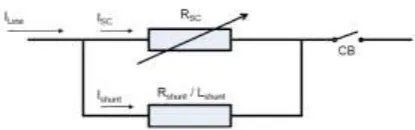
Resistive SFCLs utilize the superconducting material as the main current carrying conductor under normal grid operation. The principle of their operation is shown in the one-line diagram below (Figure 1).
Figure 1: Resistive type SFCL with shunt element
When the current passes through the superconductor and when a high fault current begins, the superconductor quenches: it becomes a normal conductor and the resistance rises sharply and quickly. This extra resistance in the system reduces the fault current. Superconductor quenches under excessive fault current reverting to a normal conductor, inserting resistance. The current level at which the quench occurs is determined by the operating temperature, and the amount and type of superconductor. The rapid increase in resistance produces a voltage across the superconductor and causes the current to transfer to a shunt, which are a combined inductor and resistor. The shunt limits the voltage increase across the superconductor during a quench. In essence, the superconductor acts like a switch with millisecond response that initiates the transition of the load current to the shunt impedance. Ideally, the incipient fault current is limited in less than one cycle. Early resistive SFCL designs experienced issues with “hot spots”, or non-uniform heating of the superconductor during the quench. This is a potential failure mode that occurs when excessive heat damages the HTS material. Recent advances in procedures for manufacturing HTS materials coupled with some creative equipment designs have reduced the hotspot issue. The grid characteristic of the resistive SFCL after a quench is determined by the shunt element. Thus, because the shunt is typically quite reactive, a resistive SFCL typically introduces significant inductance into the power system during a fault. During the transition period when current is being transferred from the superconductor to the shunt, the voltage across the combined element is typically higher than it is after the current has transitioned into the shunt. The dynamics of this process depend on the two elements
and their mutual inductance. The quench process in resistive SFCLs results in heat that must be carried away from the superconducting element by the cryogenic cooling system. Typically, there is a momentary temperature rise in the superconducting element that causes a loss of superconductivity until the cryogenic system can restore the operating temperature. This period of time is known as the recovery time. To effectively ensure the reliability of power systems, an appropriate SFCL location needs to be considered. An installation site of SFCL can be set to suitable candidate location to improve the fault-current limiting performance.
III. SIMULATION SETUP
Mat lab/Simulink/SimPowerSystem was selected to design and implement the SFCL model. Simulink/SimPowerSystem has number of advantages over its contemporary simulation software (like EMTP, PSPICE) due to its open architecture, a powerful graphical user interface (GUI) and versatile analysis and graphics tools. Control systems designed in the Mat lab/Simulink can be directly integrated with SimPowerSystem models. A complete smart grid power network including generation, transmission, and distribution with wind farm model was also implemented in it.
A. Design of Power System
Location 3(Wind farm connection point with the grid). Generally, centralized fault Current protection devices are located in Location 1 and Location 2. The output current of wind farm as well as centralized power plant for each and every fault have been measured. To reduce this wind farm fault current the Superconducting fault
current limiter used and analyzed for determining the optimum location of SFCL in a micro grid. First, we assumed that single SFCL was located at Location 1 just after the step up transformer in incoming grid feeder. Second single SFCL was located at Location 2.
Figure 2 Power system model designed in Simulink/SimPowerSystem. Fault and SFCL locations are indicated in the diagram
Third, single SFCL was located at Location 3 (Wind farm connection point with the grid). Finally, dual SFCL placed together in different locations, SFCLs were located at Location 1 (incoming grid feeder) and Location 3 (Wind Farm connection). The three phase resistive type SFCL was modeled considering four fundamental parameters of a resistive type SFCL. These parameters and their selected values are as follows: Transition or response time = 2 msec, Minimum impedance = 0.01ohms, Maximum impedance = 20 ohms, Triggering current = 500 A, Recovery time = 10 msec. To determine the minimum or maximum impedance to output switch block is used. Here the RMS value of the incoming current is calculated using RMS block. To reduce harmonics, first order filter is used. The SFCL model works as follows. First, SFCL model calculates the RMS value of the passing current and then compares it with the characteristic table. Second, if a passing current is larger than the triggering current level, SFCL’s resistance increases to maximum impedance level in a pre-defined response time. Finally, when the current level falls below the triggering current level the system waits until the recovery time and then goes in to the normal state.
B. Simulation Analysis
Four scenarios of SFCL’s possible locations were analyzed for three different fault occurring points in the power system depicted in Fig. 2. First, we assumed that single SFCL was located at Location 1 (incoming grid feeder just after step up transformer). Second, single SFCL was located at Location 2 (Branch Network). Third, single SFCL was located at Location 3 (Wind farm
integration point with the grid). Finally, in order to clarify the usefulness of dual SFCL installed together for different locations, SFCLs were located at Location 1 (incoming grid feeder) and Location 4 (Wind Farm) respectively. The feasibility analysis has been done by considering three faults at different locations i.e. Fault 1, Fault 2 and Fault 3 as shown in Fig. 2.Three phase fault has been simulated for a period of 0.05 seconds to 0.08 seconds that is fault occurred at 0.05 second and it cleared at 0.08 second. When a fault occurs in power system the fault current always flows towards fault point.
Figure 3 Single phase SFCL model developed in Simulink/SimPowerSystem
406 also closer to the Fault 1 is now forced to supply larger fault current to fault point (Fault 1).
In case of fault at point 1 with SFCL located at location 1, fault current approaching from wind farm does not flow through the SFCL located at location 1. Thus, fault current approaching from wind farm towards fault point 1 cannot be controlled to much extent as like fault current running from CPP towards fault point 1, because it traverse from SFCL at location 1. Similarly, in the presence of SFCLs at location 2 and 3 each, fault current running from CPP towards fault point 1 can’t be curtailed because SFCLs at location 2 and 3 are not in path of fault current flowing from CPP towards fault point 1. And finally, the dual SFCL location at 1 and 3 both is the optimum location at which fault current coming from two sources is restricted to a limit because both the SFCLs are in direct path of fault current from centralized power plant as well as wind farm respectively.
Case II: Transmission line fault (approximately in the mid length of CPP and wind farm ) When a fault occurs in transmission line, fault current from the centralized power plant as well as the wind farm would flow towards fault point. For the wind farm condition, fault current would flow in reverse direction through the substation and into the transmission line to fault. An important aspect to be noted here is that wind farms on distribution side can contribute fault currents to transmission line faults and this phenomenon must be considered. In case of fault at point 2 with SFCL located at location 1 and 2 each, fault current approaching from wind farm does not flow through these SFCLs. Thus, fault current flowing from wind farm towards fault point 2 cannot be controlled too much extent but fault current
running from CPP towards fault point 2is curtailed because of traversing through SFCLs at location 1 and 2 each. Similarly, in the presence of SFCLs at location 3, fault current running from CPP towards fault point 2
can’t be curtailed because SFCLs at location 3 is not in
path of fault current flowing from CPP towards fault point 2. However fault current from wind farm can be reduced satisfactorily. And finally, the dual SFCL location at 1 and 3 both is the optimum location.
Figure 5 Fault at fault point 2
Case III: Transmission line fault in close proximity to the wind farm Fault point 1 and fault point 3 are in close proximity to CPP (220 MVA) and Wind Form (9 MVA) respectively.
Figure 6: Fault at fault point 3 Table 1
407 83000A. In case of fault at point 3 with SFCL located at location 1, fault current approaching from CPP had significantly reduced because this fault current passes through SFCL at location 1. With SFCL at location 2, no discernible reduction in fault current from both the CPP and wind farm had been observed since this fault current had entered into different distribution loads. With SFCL at location 3 remarkable reductions in fault current contribution from wind farm is noted. Once again the best results are obtained when a dual SFCL is located at Location 1& 3. The Percentage decrease in centralized power plant (CPP) fault current and wind farm fault current for all considered SFCL locations are tabulated in table no 1.
IV. CONCLUSION
On connecting a Distributed Generator of large size to the distribution network the fault levels definitely increase to certain extent. This increased fault current is to be limited using the fault current limiting methods. Therefore, an application of superconducting fault current limiter (SFCL) is proposed to instantaneously limit the unanticipated fault current that occurs in power system. In the present paper, the smart grid power system model that includes centralized power plant as well as Wind farm was developed using MATLAB Simulink. To limit fault current in the developed system, by considering the fundamental parameters, single phase resistive type SFCL model was successfully developed using MATLAB Simulink. Then three R- SFCLs are collaborated to construct a three phase R-SFCL. To suppress the fault current within a minimum possible recovery time, the three phase faults have been simulated at different locations in smart grid with and without SFCL and their performance was evaluated. When a single SFCL was evaluated in an integrated power system, it can’t limit fault current from each source at a time at any fault point in the smart grid because fault current from any location can’t pass through that SFCL at any occurrence of fault. Consequently, the optimum location of SFCL in a smart grid which limits all fault currents adequately was a dual SFCL at located at main generator i.e. in incoming feeder & wind farm connection point with the grid and its remarkable performance has been suggested. Ultimately,
the reliability and stability of the power system can be improved.
REFERENCES
[1] Study of position of SFCL for maximum fault current limiter for power systems protection, Sachin Trankatwar, Dr. S. L. Nalbalwar, Dr. A. B. Nandgaonkar International Journal of Scientific & Engineering Research, Volume 4, Issue 7, 866 ISSN 2229-5518, July-2013.
[2] Application of Superconducting Fault Current Limiter in Power System by NurAmalina Abu Samah, Wan Norainin Wan Abdullah, The 4th International Power Engineering and Optimization Conf. (PEOCO2010), Shah Alam, Selangor, Malaysia: 23-24 June 2010. [3] Blair, S.M.; Singh, N.K.; Booth, C.D.; Burt, Graeme M.,
"Operational control and protection implications of fault current limitation in distribution networks, "Universities Power Engineering Conference (UPEC), Proceedings of the 44th International , vol., no., pp.1,5, 1-4 Sept. 2009.
[4] HamidJavadi, “Fault current limiter using a series impedance combined with bus sectionalizing circuit breaker”, Electrical Power and Energy Systems, 731– 736, 2011.
[5] Noe M, Oswald B. Technical and economical benefits of superconducting fault current limiters in power systems. IEEE Trans ApplSupercond, 1347–50, 1999. [6] Sung-Hun Lim, Jin Seok Kim, Myong Hyon Kim,
Jae-Chul Kim, “Improvement of Protection Coordination of Protective Devices through Application of a SFCL in a Power Distribution System with a Dispersed
Generation”, IEEE Transactions on Applied
Superconductivity, 5601004-5601004, 2012.
[7] B. C. Sung, D. K. Park, J. W. Park, and T. K. Ko, “Study on a series resistive SFCL to improve power system transient stability: modelling, simulation and experimental verification,” IEEE Trans. Industrial Electron., vol. 56, no. 7, pp. 2412–2419, Jul. 2009. [8] Litos Strategic Communication, “The Smart Gird: An
Introduction,” 2008 [Online]. Available:
http://www.oe. energy.gov/ Smart Grid Introduction.htm, Prepared for U.S. Department of Energy.