59 | P a g e
POSITION AND SPEED CONTROL OF BRUSHLESS DC
MOTORS USING SENSORLESS TECHNIQUES
Ramanuj Nigam
1, Govind Pandya
11Bhopal Insitute of Technology & Science, Bhopal M.P., India.
ABSTRACT:Brushless DC (BLDC) motor drives are popularly used in both consumer and industrial applications owing to its compact size, controllability and efficiency. BLDC motor is usually operated with one or more rotor position sensors, since the electrical excitation must be synchronous to the rotor position. To reduce cost and complexity and also to improve reliability of the drive system, sensorless drive is preferred. This paper presents the development of sensorless control system for brushless DC motor using terminal voltage sensing method without using any position sensors such as hall sensors or encoders. The simulation for proposed system is done using MATLAB. The BLDCM can act as an alternative for traditional motors like induction and switched reluctance motors. In this paper hysteresis current controller is implemented with speed feedback loop and it is observe that torque ripples are minimized. Simulation is carried out using MATLAB / SIMULINK. The results show that the performance of BLDCM is quite satisfactory for various loading conditions.
Keywords: Brushless DC sensorless control, Terminal Voltage Sensing, RC network, Hall Effect Position-sensorless control, Torque Pulsation.
1. INTRODUCTION:
BLDC motors are very popular and are replacing brush motors in numerous applications due to their high efficiency, high power density and large torque to inertia ratio. Brushless DC (BLDC) motor is inherently electronically controlled, and requires rotor position information for the proper commutation of the current, this information can be obtained using hall sensors mounted on a rotor. This results in a high costs as well as poor reliability. During last two decades, numerous researches on sensorless control approaches for BLDC motor have been conducted. In order to obtain an accurate and ripple-free instantaneous torque of BLDC motor, the rotor position information for stator current commutation must be known, which can be obtained using hall sensors mounted on a rotor. By comparing with PMSM, BLDC motor has the advantages of high speed adjusting performance and power density. The torque ripple reduction and the control show improvement of BLDC mainly focused on commutation torque ripple, the torque ripple produced by diode freewheeling of inactive phase, and the torque ripple caused by the non ideal back electromotive force (EMF). BLDCs achieve commutation electronically by in corporating a feedback from the rotor-position into a control system instead of mechanical commutators found in brushed dc motors. Such a controller excites the stator coils of the motor in a specific order to rotate the magnetic field generated by the coils to be followed along by the rotor. In case of non-ideal motors, the distributed magneto motive force is not perfectly sinusoidal and hence sinusoidal commutation leads to torque ripple. With the suppression of torque ripple the performance of the motor drive performance can be improved by reducing speed fluctuations. By
60 | P a g e
2. MODELLING AND SENSORLESS CONTROL PRINCIPLES OF BLDC MOTOR:
2.1. Modelling of the BL DC motor:
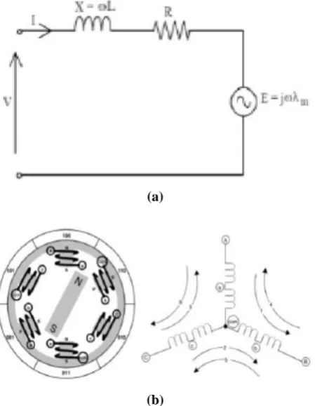
A BLDC motor has three stator phase windings connected in star fashion. Permanent Magnets (PMs) are mounted on the rotor. Fig.1 shows the equivalent circuit of a BLDC motor and Fig. 2 illustrates the relationship between the back EMF waveform of an ideal BLDC motor and the armature current, where E, I denotes the amplitude of back EMF and current respectively. The currents should have a rectangular waveform and must be in phase with the corresponding phase back EMF.
(a)
(b)
Fig. 1: BLDC motor a) equivalent circuit and b) structure and star connected armature
Fig. 2: Waveforms of ideal back EMF and phase current.
3. PROPOSED SENSORLESS CONTROL USING TERMINAL VOLTAGE SENSING:
Brushless dc (BLDC) motors, with their trapezoidal electromotive force (EMF) profile, requires six discrete rotor position information’s for the inverter operation. These are typically generated by Hall- effect switch sensors placed within the motor. However, it is a well-known fact that these sensors have a number of drawbacks. They increase the cost of the motor and need special mechanical arrangements to be mounted. Further, Hall sensors are temperature sensitive, and hence limit the operation of the motor. They could reduce system reliability because of the extra components and wiring. So sensor less method is the reliable method used in harsh environments. There are two independent methods for determining the Hall configuration. The selection of which method to use will depend on the information provided.
A. Terminal Voltage Sensing:
The Hysteresis comparator with zero cross detection technique is achieved by sensing the terminal voltage.
Figure.3 shows the block diagram of a sensorless control by using terminal voltage method. It consists of the Low Pass Filters (LPFs) for suppressing the high switching frequency ripples and comparators for compensating phase lag of terminal voltage if occurred at high speed. Motor neutral point voltage information is not used in this method. After sensing the three-phase terminal voltages, each of the three phase terminal voltages is fed into an LPF to suppress the high switching frequency ripple or noise. As only two phases of the BLDC motor are energized at any time, the back-EMF can be measured from its terminal voltage in the period of an open phase (60°). During the two phase conduction period (120°), the only difference between the back-EMF and its terminal voltage is a stator impedance voltage drop, which may be considerably small as compared with the dc voltage source. Therefore, the waveform of the terminal voltage is nearly the same as that of the back-EMF. The terminal voltages can be used to detect the commutation points of the BLDC motor instead of the back-EMFs.
61 | P a g e
B. Low Pass Filter (LPF):
Each of the three phase terminal voltages is fed into an LPF to suppress the high switching frequency ripple or noise.
Hence there are three low-pass filters (LPFs) are utilized to eliminate higher harmonics in the phase terminal voltages caused by the inverter switching.
C. Hysteresis Comparator with Zero Cross Detection:
The hysteresis comparator is used to compensate for the phase lag of the back-EMFs due to the LPF in order to determine the proper commutation sequence of the inverter according to the rotor position. Also, it can prevent multiple output transitions by high frequency ripples in the terminal voltages. There are three hysteresis comparators are used, each terminal voltage output from LPF are fed into comparator. As the rotor speed increases, the percentage contribution of the phase lag to the overall period increases. The lag will disturb current alignment with the back-EMF and will cause serious problems for commutation at high speed. The phase lag in commutation can produce significant pulsating torques in such drive which may cause oscillations of the rotor
speed, and generate extra copper losses. The output of hysteresis comparator is fed into zero cross detector.
4. SIMULATION RESULTS:
A three BLDC motor is fed to the inverter bridge and it is connected to controlled voltage source. The inverter gates signals are produced by decoding Hall Effect signals. The three phase output of the inverter is applied to the motors stator windings. From the supply voltage divider is connected, with the RC low pass filter and a compare to zero circuit to produce the back emf for three phases. After simulating the circuit on the Matlab/Simulink, Motor rotor speed. Electromotive force, stator current and electromotive torque are shown in fig.
The performance of the drive is further improved by use of LPF and hysteresis comparator, which suppress high frequency switching noise and also prevent output transitions due to harmonics. Let us take the above said values from the Fig. For one cycle.) We get the torque ripple value is 0.078%. Still further reduction in torque ripple can be achieved by selecting optimum value of PI controller constants also stator current ripple value is 0.38%.
62 | P a g e
Improved back Electro motive force detected from proposed method
5. CONCLUSION:
In this paper a review of position control methods for BLDC motors has been presented. The fundamentals of various techniques have been introduced, mainly back-EMF schemes and estimators, as a useful reference for preliminary investigation of conventional methods. Advances in the position control and applications were also discussed. To provide insight in control techniques and their benefits a classification of existing methods and newer methods were presented with their merits and drawbacks. From the above discussion, it is obvious that the control for BLDC motors using position sensors, such as shaft encoders, resolvers or Hall-effect probes, can be improved by means of the elimination of these sensors to further reduce cost and increase reliability. Furthermore, sensorless control is the only choice for some applications where those sensors cannot function reliably due to harsh environmental conditions and a higher performance is required.
REFERENCES:
1. Iizuka, K.; Uzuhashi, H.; Kano, M.; Endo, T.; Mohri, K. Microcomputer Control for Sensorless Brushless Motor. IEEE Trans. Ind. Appl. 1985, IA-21, 595-601
2. Becerra, R.C.; Ehsani, M. High-Speed Torque Control of Brushless Permanent Magnet Motors.
IEEE Trans. Ind. Electron. 1988, 35, 402-406. 3. Hubik, V.; Sveda, M.; Singule, V. On the
Development of BLDC Motor Control Run-Up Algorithms for Aerospace Application. In
Proceedings of the 13th Power Electronics and Motion Control Conference (EPE-PEMC 2008), Poznan, Poland, September 2008; pp. 1620-1624. 4. F. Filicori, C. G. L. Bianco, and A. Tonielli,
“Modeling and control strategies for a variable reluctance direct-drive motor,” IEEE Trans. Ind. Electron., vol. 40, no. 1, pp. 105–115, Jan. 1993. 5. Brushless DC Motor Control using the LPC2141
Application Note; AN10661, NXP Semiconductors: Eindhoven, the Netherlands, October 2007.
6. S. Ogasawara and H. Akagi, “An approach to position sensorless drive for brushless dc motors,”
IEEE Trans. Ind. Applicat., vol. 27, pp.928–933, Sept./Oct. 1991.
63 | P a g e 8. Muhammad H. Rashid, “Power Electronics”, Second
Edition, Pearson Education.
9. C.-G. Kim, J.-H.Lee, H.-W.Kim, and M.-J.Youn, “Study on maximum torque generation for sensor less controlled brushless DC motor with trapezoidal back ELECTRO MOTIVE FORCE,” IEE Proc.-Electro. Power Appl., vol. 152, no. 2, pp. 277–291, Mar. 2005.
10. J. H. Song and I. Choy, “Commutation torque ripple reduction in brushless dc motor drives using a single dc current sensor,” IEEE Trans. Power Electron., vol. 19, no. 2, pp. 312–319, Mar. 2004.
11. S. Wu, Y. Li, X. Miao, “Comparison of Signal Injection Methods for sensor less control of PMSM at Very Low Speeds”, IEEE Power Electronics Specialists Conference, PESC 2007, June 2007 pp. 568 – 573.
12. M. Eskola, H. Tuusa, “Sensor less Control of Salient Pole PMSM Using a Low –Frequency Signal Injection”, European Conference on Power Electronics and Applications, Sept. 2005, pp. 1- 10 13. S. Ogasawara, H. Akagi, “An Approach to
Real-Time Position Estimation at Zero and Low Speed for a PM Motor Based on Saliency”, IEEE Transactions on Industry Applications, Vol. 34, No. 1, Jan./Feb 1998, pp. 163-168
14. JoohnSheok Kim, Seung Ki Sul, “New Stand-Still Position Detection Strategy for PMSM Drive without Rotational Transducers”, Conference Proceedings of the Ninth Annual Applied Power Electronics Conference and Exposition, APEC '94., Vol. 1, 13-17 Feb. 1994, pp.363 – 369
15. US Patent No.4654566, “Control system, method of operating an electronically commutated motor, and laundering apparatus,” granted to GE.
16. T.Endo, F.Tajima, et al., “Microcomputer Controlled Brushless Motor without a Shaft Mounted Position Sensor,” IPEC-Tokyo, 1983.
17. K.Rajashekara, A. Kawamura, and K. Matsuse, “Sensorless Control of AC Motor Drives,” IEEE Press, 1996.
18. S.Ogasawara and H.Akagi, “An Approach tp Position Sensorless Drive for Brushless dc Motors,” IEEE Trans. on IA, Vol.27, No.5, Sept/Oct. 1991.
19. US Patent 5859520, “Control of a Brushless Motor,”granted to STMicroelectronics.
20. STMicroelectronics Application Note AN1130, “An Introduction to Sensorless Brushless DC Motor Drive Applications with the ST72141,” website www.st.com