Available Online at www.ijpret.com 51
INTERNATIONAL JOURNAL OF PURE AND
APPLIED RESEARCH IN ENGINEERING AND
TECHNOLOGY
A PATH FOR HORIZING YOUR INNOVATIVE WORK
DESIGN ANALYSIS OF TOP AND BOTTOM FRAME OF COTTON LINT BAILING
PRESS
ASHWINI R. BURGHATE, PROF. M. V. GUDADHE, TRIVENI R. PETALE
Department of Mechanical Engineering, PRMIT&R Badnera, Amravati, Maharashtra, India
Accepted Date: 03/12/2015; Published Date: 01/01/2016
\
Abstract: -In Ginning Industries, Cotton Lint Bailing Press is used for the purpose of pressing cotton, which makes it easy for further packing and handling. This pressing operation is performed with the help of three Hydraulic Cylinders located in between Top and Bottom Frame. Frame structure must be able to withstand all the forces without damage while machine is in working condition. In order to check the suitability and strength of top n bottom frame for hydraulic forces in cotton lint bailing press machine the static structural analysis is performed. Modelling of the Frame Structure is done in CATIA. Then the static structural analysis was carried out using ANSYS software. Also adopting a technique of optimization provides a better outcome.
Keywords:Finite Element Method, Frame Structure, Modelling, Static Analysis.
Corresponding Author: MR. ASHWINI R. BURGHATE
Access Online On:
www.ijpret.com
How to Cite This Article:
Ashwini R. Burghate, IJPRET, 2015; Volume 4 (5): 51-61
Available Online at www.ijpret.com 52
INTRODUCTION
In India, due to increasing demand of Cotton in textile and pharmaceutical industries, the production of cotton is increased. Cotton have to undergo certain processes to achieve two products i.e. fibres and seed. These processes are performed in Ginning industries. Ginning refers to the process of separating cotton fibres from the seeds. Bale packaging is the final step in processing cotton at the gin. For proper handling and transportation purpose, cotton is used in bale form. In Cotton Ginning Industry, Cotton gets separated from its seeds by using ginning machine and then converted into a compact bale by using Lint Bailing press.
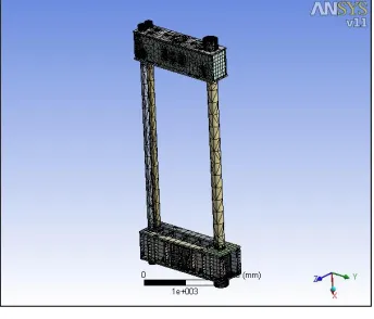
The cotton bailing press consists of Frame structure, three hydraulic cylinders, Door less cylinder, Pusher Assembly, Chambers, etc. The basic function of the Press machine is to compress the seedless cotton into a compact bale size. The Frame structure is an important part of the Press Machine. It consists of Top and Bottom Frames which are connected with the help of three tie bars. With the help of Pusher Assembly, cotton enters in one chamber. This chamber is then rotated by 180 deg. with the help of rotating disc. Hence cotton filled chamber enters in the frame structure and vacant chamber ready to get filled. In Press machine, there are three cylinders which are hydraulically operated passes through bottom frame in upward direction. On the other hand, one door less cylinder passes through the top frame in the downward direction. Then the actual pressing operation is completed. It is clear from the working of the Press machine; Frame structure plays vital role. This paper deals with the static structural analysis of top and bottom frame of cotton bailing press. This is accomplished by modelling and analysing the existing Frame structure and accordingly optimized the structure using CATIA and ANSYS Software.
Available Online at www.ijpret.com 53
15mm. According to the design and analysis results the thickness of the plate is reduced in frame.
A. G. Naik [2], addresses the analysis and optimization of hydraulic cotton lint bailing press. He observed that capacity of ginning plant is such that the cotton bale handled by their press system gives rise to very large forces and also explains the Frame structure like all the other equipment has to be able to withstand these forces without damage. Structures are becoming lighter, stronger, and cheaper as industry adopts higher forms of optimization. FEM analysis which simulated loads and the stress field which correspond to measured and calculated displacements in the crack zone, before and after the redesign, revealed a significant drop in stress in the crack zone. He concluded that the value of tensile stresses developed in the system is greater than the permissible limit. Selection of good shape provides strength to the system as the system is only undergoing through bending according to the FEA Analysis the best solution is obtained by changing the shape and design of the top and bottom frame structure.
Satish G Sonwane [3] in this paper, he took the ‘hooping platen’ of 400-ton cotton baling press as research object, established its 3D model through CATIA software. Then carried out finite element analysis for it by using FE software ANSYS 13.0 to gain the stress and strain distribution of the platen. At the end, shape optimized design model is compared with the actual part that is being manufactured for the press. It also serve as guidance to further improve its performance with less cost; at the same time provide a theoretical basis for the structural design of the same type of platens. He concluded that the maximum von-mises stress of the platen are far less than the materials yield limits at major locations in working condition, and there is a lot of optimization design space, can consider reducing materials and reduce costs. As per the results, it can be concluded that the weight of optimized design is up to 20% lighter and maximum stress also predicted lower than the initial design of platen. The figure shows that max von mises stress of the platen is far less than the materials yield limits in the working condition.
Available Online at www.ijpret.com 54
optimization is done for frame and upper head. From results we can say that as the thickness is reduced the maximum stress in the frame is increased but still it is well below the yield stress of the mild steel.
Analysis Procedure:
CATIA is used for modelling the frame structure which is a multiplatform CAD/CAM/CAE commercial software suite. This model is then used for the static analysis, to study the loading conditions and stress distribution on the frame. For this purpose, ANSYS Workbench is better option among the other analysis software. Hence, to achieve the objectives following procedure is used:
Firstly, the frame structure including tie bars, Top and Bottom Frame is modelled according to the dimensions in CAD Software i.e. CATIA v5R17.
This model is then converted into IGES format for importing it to analysis software.
This model is then analysed in ANSYS Software to study the stresses and loading conditions on the Frame.
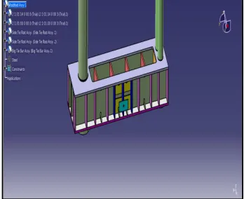
In ANSYS Workbench, first we need to select convenient unit system for the analysis. Then importing the geometry which was modelled in CATIA and saved as IGES file format.
Then the Meshing is performed on the model. It is better to use Tetrahedron triangular type for meshing complex geometry to get accurate results.
Available Online at www.ijpret.com 55
Select the type of analysis as Static Structural for the evaluation of the solution.
Now, the next step is to apply the loading conditions on the frame structure. So, the types of loading that can be applied in a static analysis includes externally applied forces and pressures, steady state internal forces like gravity and fixed support.
Fig 2 Model with Boundary Conditions
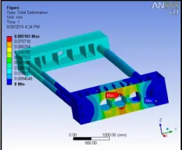
After discretization of the frame and providing the necessary boundary conditions, as a result the stress distribution and deformation value on the frame is observed.
Fig 3 ANSYS Result for Von Mises Stress of Existing Frame
Available Online at www.ijpret.com 56
Optimization of Top & Bottom Frame:
Optimization is an act, process, or methodology of making something (as a design, system, or decision) as fully perfect, functional, or effective as possible. In this Frame structure, there are two frames that is top and bottom. Both the frames have one plate which is made of four different parts. These parts are attached with the help of bolts to other parts of top and bottom frames. After studying the availability of the same material in required thickness, the above four parts can be replaced by a single plate. One of the purposes of optimization in first modification is the uniform stress distribution.
Fig 5. Frame structure of Existing Model
Fig 6. Frame structure after 1st modification
Available Online at www.ijpret.com 57
Fig 7 Frame Structure after 2ndmodification
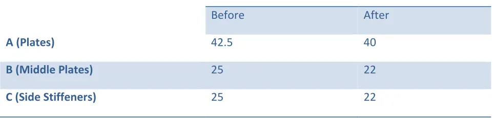
Table 1 shows dimensional change in frame structure
RESULT AND DISCUSSION:
As per the requirements, the analysis for the original frame structure is performed and the required modifications are carried out. After the first modification is performed, cost and time required for machining can be reduced. Also, the stress distribution is uniform and considerably reduced than obtained for original frame. Hence, the following figure shows the von-misses stress and deformation for the modified frames.
For both the frames Thickness, mm
Before After
A (Plates) 42.5 40
B (Middle Plates) 25 22
C (Side Stiffeners) 25 22
A B
Available Online at www.ijpret.com 58
Fig 8 ANSYS Result for Von Mises Stress of 1st Modified Frames
Fig 9 ANSYS Result for Total deformation of 1st Modified Frame
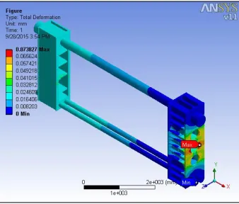
It can be observed that after the modification, the stress distribution is uniform throughout the plate of the frames than the original frame. Hence, the amount of stress is minimized. In general, deformation refers to any changes in the shape or size of an object due to an applied force. Hence, as the stress is decreased, the deformation is also reduced.
After the analysis of the modified frame, it is observed that the weight of the frame is increased. Hence to compensate and save the material, the thickness is reduced in second modified model of the frame structure. So, following are the results obtained by the analysis after the modification.
Available Online at www.ijpret.com 59
Fig 10 ANSYS Result for Von Mises Stress of 2nd Modified Frames
Fig 11 ANSYS Result for Total deformation of 2nd Modified Frame
The above result shows minor difference of stress and deformation values than first modified model. Hence, we can state that the loading condition does not affect the frame structure due to reduction in thicknesses. Following table shows the comparison of the analysis results obtained considering the important parameters after performing all the modifications.
Table 2 Comparison of results for Weight, Von-misses stress and Total deformation
Results Existing Modifications
Modification 1 Modification 2
Weight (Kg) 9423.3 9570 9395.4
Available Online at www.ijpret.com 60
CONCLUSION:
An attempt was made to analyse and optimize the frame structure of cotton lint bailing press machine using ANSYS software.
Firstly, the original frame structure is analysed and then the results are obtained.
After the first modification that is using a single complete plate instead of joining the parts, the results conclude that the stresses and deformation are within the limit which means the modification is safe to apply and the machining time and cost required can be reduced.
But it was observed that the weight of the frame is increased. So, to avoid it second modification was performed. In this, the material used for the plates in the frame is reduced by decreasing the thickness.
After the second modification, the values obtained related to the Stress and Deformation are within the limit. Hence, we can say that the model is safe.
Therefore, it can be concluded that by performing relevant modifications in the frame structure we can improve the performance of the structure.
REFERENCES:
1. B. Parthiban, “Design and Analysis of C Type Hydraulic Press Structure and Cylinder”, IJRAME
2014, ISSN (ONLINE): 2321-3051, Vol.2 Issue.3.
2. A. G. Naik, “Review On Analysis and Optimization of Hydraulic Cotton Lint Bailing Press”, ARPN Journal of Engineering and Applied Sciences 2012, ISSN 1819-6608, Vol 7.
3. Satish G Sonwane, “Structural Optimization of Hooping Platen of 400ton Cotton Baling Press
for Cost Reduction”, IJPRET 2014, ISSN: 2319-507X, volume 2 (9): 379-389.
4. S. M. Bapat, “Design and Optimization of A 30 Ton Hydraulic Forming Press Machine”, IJRASET 2014.
5. Madhu P.S, “Static Analysis, Design Modification and Modal Analysis of Structural Chassis Frame”, IJERA 2014, ISSN: 2248-9622, Vol. 4, Issue 5(Version 3).
Available Online at www.ijpret.com 61
6. J. F. Agrawal, “Design of Medium Duty Mechanical Press for Ginnery”, Journal of Industrial Engineering.
7. Ketan Gajanan Nalawade, “Dynamic (Vibrational) And Static Structural Analysis of Ladder Frame”, IJETT 2014, Volume 11 Number 2.