Available Online at www.ijpret.com
146
INTERNATIONAL JOURNAL OF PURE AND
APPLIED RESEARCH IN ENGINEERING AND
TECHNOLOGY
A PATH FOR HORIZING YOUR INNOVATIVE WORK
PERFORMANCE AND ANALYSIS OF FOUR SWITCH THREE PHASE INVERTER
CONTROL FOR BLDC MOTOR USING MATLAB
PRASHANT R. CHAHANDE1, DR. (MRS.) S. P. MULEY2, PROF. S. C. SUKE2
1. M. Tech, Industrial Drives and Control, Priyadarshini College of Engineering, Nagpur, Maharashtra, India.
2. Department of Electrical Engg., Priyadarshini College of Engineering, Nagpur, Maharashtra, India.
Accepted Date: 24/04/2014 ; Published Date: 01/06/2014
Abstract:The main objective of this paper is to describe a low cost four-switch brushless dc
(BLDC) motor drive for commercial applications. Speed control of three phase BLDC motor using four switch inverter is proposed to simplify the structure of the conventional six switch inverter. For effective utilization of the developed system, a novel direct current controlled PWM scheme is designed and implemented to produce the desired dynamic and static speed–torque characteristics. PI controller is used by the outer loop to develop the performance of speed control. The operational principle of the four-switch BLDC motor drive and the developed control scheme are theoretically analyzed and the performance is demonstrated by both simulation and experimental results in MATLAB.
Keywords: BLDC motor, Four-switch three phase inverter
Corresponding Author: MR. PRASHANT R. CHAHANDE
Access Online On:
www.ijpret.com
How to Cite This Article:
Prashant Chahande, S. P. Muley, S. C. Suke; IJPRET, 2014; Volume 2 (10): 146-159
Available Online at www.ijpret.com
147 INTRODUCTION
Available Online at www.ijpret.com
148 much more complicated. Moreover, in order to handle the complicated calculations in one sampling period, a high-speed digital processor is also necessary, which increases the manufacturing cost. Therefore, for the low cost BLDC motor applications, voltage vector PWM schemes cannot be regarded as a good solution for cost effective purpose. Modeling and simulation of electromechanical systems with BLDC drives are essential steps at the design stage of such systems. For the purposes of stability analysis and controller design it is often desirable to investigate the large-signal transients and small-signal characteristics of the system. Simulation studies are also often performed many times to achieve the required design goals. In this study, the nonlinear simulation model of the BLDC motors drive system with proportional-integral (PI) control based on MATLAB/Simulink platform is presented.
CONVENTIONAL METHOD FOR SPEED CONTROL OF BLDC MOTOR
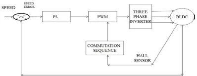
Commutation ensures proper rotor rotation of the BLDC motor, while the motor speed depends only on the amplitude of the applied voltage. The amplitude of the applied voltage is adjusted by using the PWM technique. The required speed is controlled by a speed controller. The speed controller is implemented as a conventional PI controller. The difference between the actual and required speed is input to the PI controller and based on this difference, the PI controller controls the duty cycle of PWM pulses, which corresponds to the voltage amplitude required to keep the required speed.
Fig 1. Conventional block diagram for Speed control of BLDC motor
The speed controller calculates a Proportional-Integral algorithm according to the following equation is u(t) = kce(t) + ∫ ( ) (9)
Available Online at www.ijpret.com
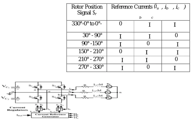
149 illustrated in fig 2. The power stage utilizes six power transistors with switching in either the independent mode or complementary mode. In both mode, the 3-phase power stage energizes two motor phases concurrently. The third phase is unpowered. Thus, six possible voltage vectors are applied to the BLDC motor using a PWM technique. There are two basic types of power transistor switching, independent switching and complementary switching, which are discussed in the following sections. Fig. 3 shows the configuration of a four-switch inverter for the three-phase BLDC motor. It has two common capacitors, instead of a pair of bridges are used and phase c is out of control because it is connected to the midpoint of the series capacitors. From fig. 2, the phase current cannot hold at zero and it causes an additional and unexpected current, resulting in current distortion in phases a and b and even in the breakdown of the system. The same problem is inherited by the four-switch mode and it causes the produced voltage vectors to be limited and asymmetric, which were well known as asymmetric voltage vectors. In Table 1 show the basic operating principle of BLDC.
II. DESCRIPTION OF PMBLDCM DRIVE
Commutation ensures proper rotor rotation of the BLDC motor, while the motor speed depends only on the amplitude of the applied voltage. Fig.2 describes the basic building blocks of the PM BLDC motor drive. The drive consists of speed controller, reference current generator, pulse width modulation (PWM) current controller, position sensor, the motor and a IGBT based voltage source inverter (CC-VSI). The speed of the motor is compared with its reference value and the speed error is processed in PI speed controller. The output of this controller is considered as the reference torque. A limit is put on the speed controller output depending on permissible maximum winding currents. The reference current generator block generates the three phase reference currents (ia*, ib*, ic*) using the limited peak current.
Available Online at www.ijpret.com
150 Fig.4 PI-Speed Controller
The PI controller is widely used in industry due to its ease in design and simple structure. The rotor speed ωr(n) is compared with the reference speed ωr(n)* and the resulting error is estimated at the nth sampling instant as:
ω ( n ) = ω ( n ) * − ω ( n ) (1)
The new value of torque reference is given by
T (n)=T (n-1) + KPωe (n) − ωe (n-1) + K1ωe (n) (2)
Where ‘ωe(n − 1)’ is the speed error of previous interval, and ‘ωe(n)’ is the speed error of the working interval. KP and KI are the gains of proportional and integral controllers respectively. By using Ziegler Nichols method the KP and KI values are determined [10]
REFERENCE CURRENT GENERATOR:
Unlike a brushed DC motor, the commutation of a BLDC motor is controlled electronically. To rotate the BLDC motor, the stator windings should be energized in a sequence. Most of BLDC motors have three Hall sensors embedded into the stator on the non-driving end of the motor. Rotor position is sensed by Hall Effect sensors embedded into the stator which gives the sequence of phases. Whenever the rotor magnetic poles pass near the Hall sensors, they give a high/low signal, indicating the N or S pole is passing near the sensors. Based on the combination of these three Hall sensor signals, the exact sequence of commutation can be determined. The magnitude of the reference current (I∗) is determined by using reference torque (T∗) and the back emf constant (Kb) ∗ =
∗
Depending on the rotor position, the reference current generator block generates three-phase reference currents (ia∗, ib∗, ic∗)
Available Online at www.ijpret.com
151 Fig.5 Back EMF, current profile, modes, conducting switches in the four-switch converter for three-phase BLDC motor drives
Fig.6 Inverter circuit with BLDC Motor drive
Terminal voltages of a BLDC motor in the four switch inverter with respect to the mid-point of the dc bus are as follows:
(3)
(4)
(5)
III. OPERATIONAL PRINCIPLE OF
DIRECT CURRENT CONTROLLED PWM
Available Online at www.ijpret.com
152
Rotor Position
Signal θr
Reference Currents (ia∗, ib∗, ic∗)
b c
330°-0° to 0°- 0 −I
∗
I∗
30° - 90° I −I 0
90° -150° I 0 −I
150° - 210° 0 I∗ −I
210° - 270° −I I∗ 0
270° - 330° −I 0 I∗
four-switch phase BLDC motor drives as follows: Under a balanced condition, the three-phase currents always satisfy the following condition.
(6)
Then, (1) can be modified as
(7)
In the case of the ac induction motor drive, at any instant there are always three phase currents flowing through the load, such as
Ia≠0; Ib≠0; Ic≠0 (8)
However, in the case of the BLDC motor drive, (3) is not valid anymore. Note that in Fig. 5. phase A and B currents are only controllable and phase C is uncontrollable. According to the operating modes, one can derive the following current equations: Table I implies that due to the characteristics of the BLDC motor, such as two-phase, only two phases (four switches) needed to be controlled, not three phases. Therefore, based on Table I, one can develop a switching sequence using four switches as follows:
Table 1.Rotor position signal Vs reference current
Available Online at www.ijpret.com
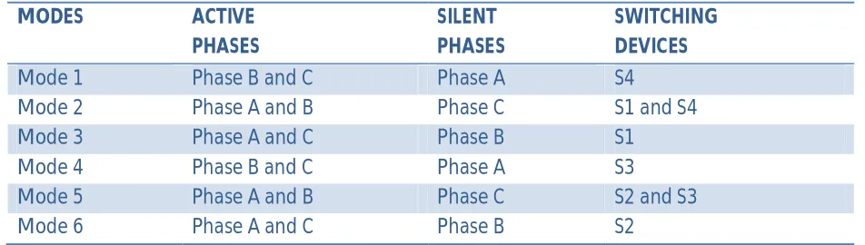
153 As shown in Table II, the two-phase currents need to be directly controlled using the hysteresis current control method by four switches. Hence, it is called the direct current controlled PWM scheme. Based on the direct current controlled PWM, implementation of the switching sequence and current flow are depicted in Fig. 6.
Table 2. Switching Sequence of Four switch BLDC motor
MODES ACTIVE
PHASES
SILENT PHASES
SWITCHING DEVICES
Mode 1 Phase B and C Phase A S4
Mode 2 Phase A and B Phase C S1 and S4
Mode 3 Phase A and C Phase B S1
Mode 4 Phase B and C Phase A S3
Mode 5 Phase A and B Phase C S2 and S3
Mode 6 Phase A and C Phase B S2
As shown in Table II, the two-phase currents need to be directly controlled using the hysteresis current
control method by four switches. Hence, it is called the direct current controlled pwm scheme. Based on the direct current controlled pwm, implementation of the switching sequence and current flow are depicted in Fig. 6.
(a) (b)
Available Online at www.ijpret.com
154 (c) (d)
(e) (f)
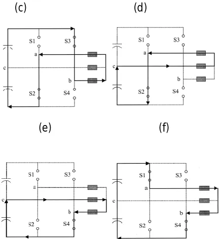
Fig. 7 Implementation of the direct current controlled pwm strategy. (a) ModeI (S4). (b) Mode II (S1 and S4). (c) Mode III (S1). (d) Mode IV (S3). (e) Mode V (S3 and S2). (f) Mode VI (S2).
CURRENT REGULATION
Available Online at www.ijpret.com
155 as shown in Fig. 6(c). However, the same principle as used for mode II is applied to mode III. When Ia increases,S1 is turned on and other case S1 is turned off.
Fig.8 Current regulation and detailed switching sequences.
IV. SIMULATION RESULTS
In this work the drive model with PI speed controller is developed and simulated in order to validate the four switch three phase inverter control of BLDC motor model and the designed controller. For conducting the studies and analysis, this paper considers a typical BLDC motor with importance specification Rated power = 1.03 Kw Pole = 4 Rs= 18.7 Kt = 1.0302 Ki = 0.008
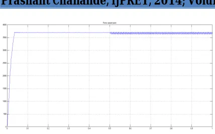
Fig.9-12 shows simulated results with settling time is 0.5 sec.
Available Online at www.ijpret.com
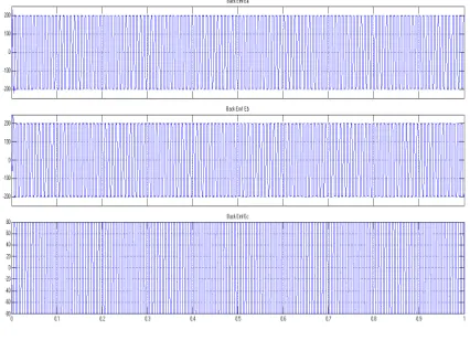
156 Fig 10 (a) Trapezoidal back EMF
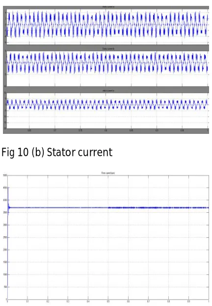
Fig 10 (b) Stator current
Available Online at www.ijpret.com
157 Fig. 10 Simulink model of closed loop BLDC motor feed by three phase Four switch Inverter
Fig 11 (a) Trapezoidal back EMF
Available Online at www.ijpret.com
158 Fig 11 (c) Control rotor speed in rpm
Conclusion: The simulation model of the BLDC motors drive system with PI control based four switch three phase inverter on MATLAB/Simulink platform is presented to provide a possibility for the realization of low cost and high performance three-phase BLDC motor drive system. From the observation, one should note that the development of the proper pwm control strategy should be accompanied with the reduced parts converter. As a solution, we propose the direct current controlled pwm and examine the performance. With the developed control scheme, it is expected that the proposed system can be widely used in commercial applications with a reduced system cost.
REFERENCES:
1. R. G. Shriwastava, M. B. Diagavane, S. R. Vaishnav, “Literature Review of Permanent Magnet AC Motors Drive for Automotive Application”, Buletin TEI March 2012, Vol.1 No.1 pp. 7-14 ISSN: 2089-3191.
2. Pragasan Pillay and R. Krishnan Member IEEE “Modeling of Permanent Magnet Motor Drives” N-1988 Transaction On Industrial Electronics, Vol.35, No.4. pp 537-541.
3. G. Prasad, N. Sree Ramya, P. V. N. Prasad, G. Tulasi Ram Das “Modeling and Simulation Analysis of the Brushless DC Motor by using MATLAB” O-2012 International Journal of Innovative Technology and Exploring Engineering (IJITEE) ISSN: 2278-3075, Volume-1, Issue-5.
4. R. Shanmugasundram, K. Muhammed Zakariah, N. Yadaiah Member IEEE “Low-Cost High Performance Brushless DC Motor Drive for Speed Control Applications” 2009 International Conference on Advances in Recent Technologies in Communication and Computing 978-0-7695-3845.
Available Online at www.ijpret.com
159 of Innovative Technology and Exploring Engineering D-2012 ISSN: 2278-3075, Volume-2, Issue-1.
6. Vinod Kr Singh Patel, A. K. Pandey “Modeling and Simulation of Brushless DC Motor Using PWM Control Technique” International Journal of Engineering Research and Applications May-Jun 2013 ISSN: 2248-9622 Vol. 3, Issue 3 pp.612-620.
7. Purna Chandra Rao , Y. P. Obulesh2 and Ch. Sai Babu “Mathematical Modeling Of Bldc Motor with closed loop Speed Contol Using pid Controller under Various Loading Conditions” ARPN Journal of Engineering and Applied Sciences O- 2012 volume 7, No. 10 ISSN 1819-6608 PP. 1321-1328.
8. Jibin M Varghese, Jaya B and Justin Baby “PI tuning control of Four Switch Three Phase Brushless DC Motor” Jan.2008 IEEE transaction Power Electron, volume 23, no1, pp 438-444.
9. J. Karthikeyan Dr. R. Dhanasekaran “Simulation and Implementation of current control of Brushless Motor based on a common dc signal” International Journal of Engineering Science and Technology S-2010 Vol. 2(6), 1632-1639.
10.M. Vignesh Kumar “Speed controls of three phase BLDC Motor using Four Switch Inverter” May-2013 International Journal of Scientific & Engineering Research ISSN 2229-5518 Volume 4, Issue 5 pp. 351-356.
11.V. Krishnakumar, Dr. S. Jeevanandhan “Four Switch Three Phase Inverter Control of BLDC Motor” International Conference on Electrical Energy Systems 2011 pp. 139-144