1Department of Mechanical Engineering, Korea Maritime and Ocean University, Busan, Korea 2School of Intelligent Mechatronics Engineering, Sejong University, Seoul, Korea
3Chief of Marine Unmanned System Center, Korea Maritime and Ocean University, Busan, Korea
Received 26 April 2019; received in revised form 01 June 2019; accepted 31 August 2019 DOI: https://doi.org/10.46604/ijeti.2020.4158
Abstract
Detecting the relative position of the docking station is a very important issue for the homing of AUVs (Autonomous Unmanned Vehicles). To detect the position of the light source, a pinhole camera model structure was proposed like the camera model. However, due to the sensor resolution and the distortion errors of the pinhole camera system, the application of the camera of docking the under turbid sea environments is almost impossible.
In this paper, a new method detecting the position of the docking station using a light source is presented. Also, a newly developed optical sensor which makes it much easier to sense the light source than the camera system for homing of the AUV under the water is performed. In addition, to improve the system, a neural network (NN) algorithm constructing a model relating the light inputs and optical sensor which are developed in this study is proposed.
To evaluate the performance of the NN algorithm, the experiments were performed in the air beforehand. The result shows that the NN algorithm with AUV docking system using the NN model is better than the pinhole camera model.
Keywords: optical sensor, neural network, pinhole camera, navigation
1.
Introduction
AUV is suitable to perform a variety of underwater missions autonomously [1-7]. However, a docking station where the AUV can recharge the battery, transfer data, and do safe parking is needed due to the limited battery duration of AUVs.
For the AUV docking, a number of studies about the detection position of AUV in short distance have been performed so far [8-11]. Normally, they use cameras with pinhole camera method to determine the position of AUV and station as in [12] and [13]. Nevertheless, the lens of the camera is distorted and the image is imperfect; they need many feature points to estimate the position. In other studies, a camera and three artificial colored spheres are used in [14]. Because of the poor visibility in the underwater environment, colored spheres detection is very difficult to be used, which is a significant constraint for this method. There are also some studies using optical sensors as [15]. However, these methods have a disadvantage that the systems using the camera is only suitable for the distance below 10m, since they did not use a converging lens for focusing the light. Especially, under the water, the sea water is turbid so the visibility of the camera is very limited. Due to this reason, the pinhole camera is not appropriate for detection of something for docking AUV.
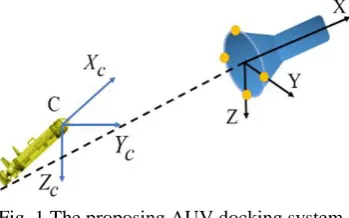
Fig. 1 The proposing AUV docking system
To overcome the restrictions of the past studies, we propose a new system using optical sensors and is able to detect much longer light source. As a docking system, the optical sensors are mounted on the nose of AUV. In addition, a converging lens and four LEDs are used as shown in Fig. 1.
A feed-forward NN model for detecting the docking system position is also proposed. In order to validate the effect of the proposed method, we perform the experiment in the air beforehand, and then compare the result of the NN with the pinhole camera algorithm. This experiment is a pre-test before applying it to an underwater system.
2.
Pinhole Camera Model
In this part, we introduce a pinhole camera model to detect the position of AUV for docking [16]. Firstly, we define the lens coordinate (C, XC, YC, ZC) which is centered at the optical center C and the docking coordinate (D, X, Y, Z) which is at center of docking entrance. In order to reduce the complexity of equations, we choose the docking coordinate as shown in Fig. 2. Two axes CYC and CZC of the lens coordinate (C, XC, YC, ZC) are parallel to the image plane while the third one CXC is the optical axis as shown in Fig. 2. The relationship between the docking coordinate and camera coordinate is simply expressed:
Fig. 2 Definition of coordinate
3
0 1
1 1
C C
T C
X X
R d
Y Y
Z Z
(1)
where (X, Y, Z) is the position of the center of dock in (D, X, Y, Z). (XC, YC, ZC) is the position of the center of dock in (C, XC, YC, ZC). R and d are rotation matrix and translation vector from (D, X, Y, Z) coordinate to (XC, YC, ZC).
0 0
0 0
1 0 0 1 1
c c
c c c c Y X Z X
x f
y f
(2)
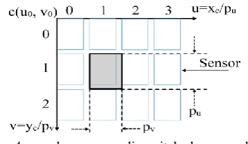
where f is the focal length of the lens. Finally, the sensor coordinate system (s, u, v) can be defined as Fig. 4.
Fig. 3 The projection from object to sensor plane
Fig. 4 pu and pv are sampling pitch along u and v
Next, we denote the sampling pitch at the physical space between (the centers of) adjacent sensor cells as in Fig. 4. Hence, the relationship between sensor coordinate (s, v, u) and the virtual image coordinate (c, xc, yc) can be expressed as:
0
0
1 / 0
0 1 /
1 0 0 1 1
u c
v c
u p u x
v p v y
(3)
3.
Neural Network Algorithm for Detection of AUV Position
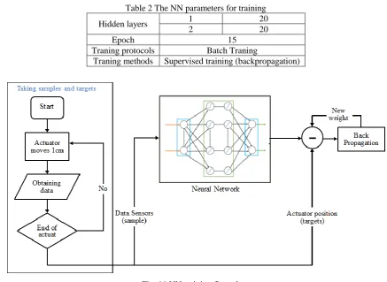
We present a feed-forward NN (in short– NN) to detect the LED position on the object using optical sensor. Fig. 5 shows the framework for training and implementing the NN algorithm. First, the network gets sensors data called as sample data. Next, the external positioning system then measures the true position of the object which is called the target data. Lastly, the back-propagation algorithm is applied to find the weights of NN to match the output of NN with the true position of the object.
Fig. 5 The framework for training and implementing a NN
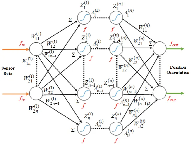
Fig. 6 expresses the structure of the feed-forward NN. Transfer function f is sigmoid function
A
1/ (1
e
Z)
. The outputfunction fout is an identity function.
Fig. 6 The feed-forward NN architecture
4.
Experiment
This section describes the experimental setup and the result of experiments in the air.
4.1. Experimental setup
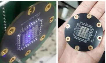
Fig. 7 Picture of the developed light sensor
Table 1 The hardware specification
Name Model Specification
Light sensor - 5x5 ISL76671 sensors
Optical sensor ISL76671
to 100 lux range
Dimension 2x2.1x0.7mm Square root voltage output
Rise time: 445us
Fall time: 405us
Motor A8K - M566
5 phase stepping motor 0.72o/step
43VDC
Fig. 8 The setting up experiment Fig. 9 The actuator bring the light
Fig. 10 The controlling system
In the experiment, two LEDs and one actuator are used to move the light sensor as shown in Figs. (8)-(9). The actuator can be considered as the point mass (so that there is no orientation). The purpose of the setting-up of the system is to determine actuator position in 2-dinmensional space. The specification of motors is shown in Table 1. The motor is controlled by PC shown in Fig. 10 and continuously moves from the start position to the end position by 0.5 cm/s. Figs. (12)-(13) illustrate the motor path for longitudinal and horizontal movements.
4.2. NN modelling experiment
sampling time until the end of movements. Secondly, the data set is used to train the NN model using the back-propagation algorithm. Finally, this trained NN model is used to detect the real position of the target. The NN parameters are expressed in Table 2.
Table 2 The NN parameters for training
Hidden layers 1 20
2 20
Epoch 15
Traning protocols Batch Traning
Traning methods Supervised training (backpropagation)
Fig. 11 NN training flow chart
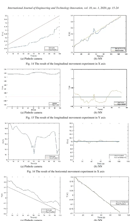
In the first experiment, the light moves along the longitudinal direction from 8m to 8.5m as shown in Fig. 12. In the second experiment, the light moves horizontally as shown in Fig. 13. The result of the first experiment is shown in Figs. 14 and 15. The result of the second experiment is shown in Figs. 16 and 17.
Fig. 12 The longitudinal movement experiment
Fig. 13 The horizontal movement experiment 4.3. Results and discussion
As shown in Fig. 14, the biggest error of the estimated value of the pinhole camera model in X coordinate is about 0.2m; while the error in NN is about 0.1m. The same result at Y coordinate is expressed as Fig. 15. The biggest error of the pinhole camera is about 0.15m and that of the NN model is 0.03m.
(a) Pinhole camera (b) NN Fig. 14 The result of the longitudinal movement experiment in X axis
(a) Pinhole camera (b) NN
Fig. 15 The result of the longitudinal movement experiment in Y axis
(a) Pinhole camera (b) NN
Fig. 16 The result of the horizontal movement experiment in X axis
(a) Pinhole camera (b) NN
In this second experiment, the biggest error value of result of pinhole camera along X coordinate is about 0.7m, which is much bigger than the error of the NN model shown in Fig. 16. But the estimation value of the NN is stable because the NN model can “learn” the parameters of system, including the disturbances such as the reflection and other noises. The result along Y coordinate is the same. The error of Pinhole camera is about 0.1m and the error of the NN model is almost zero shown in Fig. 17.
According to the experimental results, it is shown that the performance of the proposed NN model is much better than that of the pinhole camera model.
5.
Conclusions
In this paper, a new method detecting the position of the docking station for the AUV is presented using a light source and optical sensor under the water. For the docking of the AUV using the light system, a photo diode sensing system which can sense the light more sensitively is studied in this paper.
To detect the position of the light source, a new NN algorithm constructing a model relating the light inputs and optical sensor was studied to find the accurate position of the light sources. The performance of the proposed NN model was compared with the pinhole camera model which has disturbances such as reflection and lens distortion.
To verify the performance of the proposed NN algorithm, a number of experiments including the pinhole model were performed. The experimental results show that compared with the pinhole camera model, the NN model can reduce the position error about 0.1m along vertical direction and about 0.2m along horizontal direction. According to the experimental results, it was verified that the proposed NN model using the NN algorithm is more accurate than the pinhole model. For the further work, we will apply this method to an underwater AUV docking system.
Conflicts of Interest
The authors declare no conflict of interest.
Acknowledgment
This research was partially supported by Civil-Military Dual Use Technology (Grant No. :18-SN-RB-01) and Civil-Military Dual Use Technology (Grant No :17-CM-RB-16). The supports are gratefully acknolwledged.
Appendix
Firstly, we defined the rotation matrix R and translation vector d:
11 12 13
21 22 23
31 32 33
R R R
R R R R
R R R
(a) x y z d d d d (b)
From Eq. (3), we have:
c u
c v
x
p u
y
p v
(c)entrance are on X = 0 of the docking coordinate (D, X, Y, Z). From Eq. (1):
12 13
12 13 22 23
22 23
12 13 32 33
32 33
C x u
x y u C y v x z v C z
X R Y R Z d p u
R Y R Z d R Y R Z d
f p u
X R Y R Z d
p v f
R Y R Z d R Y R Z d
f p v
X R Y R Z d
f (e)
And we denote: r R12 R13 R22 R23 R32 R33 dx dy dzT. Eq. (e) can be rewritten:
0
0
1 0
0
0
0
0 1
u u u
v v v
p u p u p u
f f f
Gr
p v p v p v
f f f
Y
Z Y
Z
r
Y
Z
Y
Z
(f)If an image of the LEDs on docking are observed by stacking n, such equation as Eq. (f), and we have:
0
Gr (g)
where G is a 2n x 9 matrix. We also have:
12
22 13 23 33
32
0 R
R R R R
R (h)
Hence, if n = 4, in general, we have a unique solution of r.
References
[1] M. T. Vu, H. S. Choi, J. I. Kang, D. H. Ji and H. Joong, “Energy efficient trajectory design for the underwater vehicle with bounded inputs using the global optimal sliding mode control,” Journal of Marine Science and Technology, vol. 25, no. 6, pp. 705-714, 2017.
[2] M. T. Vu, H. S. Choi, T. Q. M. Nhat, and D. Q. Jung, “Designing optimal trajectories and tracking controller for unmanned underwater vehicles,” Recent Advances in Electrical Engineering and Related Sciences: Theory and Application, Lecture Notes in Electrical Engineering, vol. 465, pp. 658-668, 2018.
[3] M. T. Vu, H. S. Choi, T. Q. M. Nhat, D. H. Ji and H. J. Son, “Study on the dynamic behaviors of an USV with a ROV,” OCEANS-Anchorage, IEEE Press, pp. 1-7, September 2017.
[4] M. T. Vu, H. S. Choi, J. I. Kang, D. H. Ji and S. K. Jeong, “A study on hovering motion of the underwater vehicle with umbilical cable,” Ocean Engineering, vol. 135, pp. 137-157, 2017.
[5] D. W. Jung, S. M. Hong, J. H. Lee, H. J. Cho, H. S. Choi and M. T, “A study on unmanned surface vehicle combined with remotely operated vehicle system,” Proceedings of Engineering and Technology Innovation, vol. 9, pp. 17-24, 2018. [6] K. S. Nam, D. G. Lee, J. D. Ryu and K. N. Ha, “The basic study of underwater robot control for over actuated systems,”
Proceedings of Engineering and Technology Innovation, vol. 12, pp. 21-25, 2019.
[8] N. Palomeras, G. Vallicrosa, A. Mallios, J. Bosch, E. Vidal, N. Hurtos, M. Carreras, and P. Ridao, “AUV homing and docking for remote operations,” Ocean Engineering, vol. 154, pp. 106-120, 2018.
[9] T. Zhang, D. Li, and C. Yang, “Study on impact process of AUV underwater docking with a cone-shape dock,” Ocean Engineering, vol. 130, pp. 176-187, 2017.
[10] A. S. Muntadas, E. Kelasidi, K. Y. Pettersen, and E. Brekke, “Learning an AUV docking maneuver with a convolutional neural network,” IFAC Journal of Systems and Control, vol. 8, 2019.
[11] Y. Li, Y. Jiang, J. Cao, B. Wang, and Y. Li, “AUV docking experiments based on vision positioning using two cameras,” Ocean Engineering, vol. 110, pp. 163-173, 2015.
[12] T. Palmer, D. Ribas, P. Ridaoy, and A. Malliosy, “Vision based localization system for AUV docking on subsea intervention panels,” OCEANS 2009-EUROPE, IEEE Press, pp. 1-10, October 2009.
[13] J. Park, B. Jun, P. Lee, F. Lee, and J. Oh, “Experiment on underwater docking of an autonomous underwater vehicle ‘ISiMI’ using optical terminal guidance,” OCEANS 2007 - EUROPE, IEEE Press, pp. 1-6, September 2007.
[14] A. B. Figueiredo, B. M. Ferreira, and A. C. Matos, “Vision-based localization and positioning of an AUV,” OCEANS 2016 - Shanghai, pp. 1-7, April 2016.
[15] F. Eren, S. Pe’eri, M. W. Thein, Y. Rzhanov, B. Celikkol, and M. R. Swift, “Position, orientation and velocity detection of unmanned underwater vehicles (UUVs) using an optical detector array,” Sensors, vol.17, no. 8, pp. 17-41, 2017.
[16] W. M. Newman and R. F. Sproull, Principles of Interactive Computer graphics, McGraw-Hill, New York, 1979.
Copyright© by the authors. Licensee TAETI, Taiwan. This article is an open access article distributed under the terms and conditions of the Creative Commons Attribution (CC BY-NC) license