Tribology in Industry
www.tribology.fink.rsEvaluation of Tribological Properties and
Optimization of Electroless Ni-P-W Coating under
Dry Condition using Grey Fuzzy Analysis
A. Mukhopadhyay
a, S. Duari
a, T.K. Barman
a, P. Sahoo
aaDepartment of Mechanical Engineering, Jadavpur University, Kolkata 700032, India.
Keywords:
Electroless nickel Ni – P – W coating Coefficient of Friction Wear Depth
Grey – Fuzzy Logic
A B S T R A C T
Electroless Ni-P-W coating has enhanced tribological properties compared to the conventional binary alloys. Hence, electroless Ni-W-P, which is a ternary alloy, is synthesized on mild steel substrates. The coatings are heat treated at 400 °C for 1 hr to obtain a high hardness. Their tribological behavior is investigated on a pin–on–disc tribo–tester under dry condition. Three test parameters which include the applied normal load (L), sliding speed (S) and sliding time (T) are varied and their effects on wear depth and coefficient of friction are analyzed. An attempt is made to ascertain the optimum combination of the parameters that would minimize the coefficient of friction and wear depth of the deposits simultaneously using Grey Fuzzy logic. Optimum tribological behavior of the deposits is obtained at an applied normal load of 10 N, sliding speed of 80 rpm and sliding duration of 5min. Load and time are seen to be the most significant factors in influencing the friction and wear of the deposits. The variation of coefficient of friction and wear depth considering the combined effect of the aforesaid parameters is analyzed from three dimensional surface plots. The wear mechanism is found to be predominantly abrasive in nature.
© 2017 Published by Faculty of Engineering
Corresponding author:
P. Sahoo
Department of Mechanical Engineering, Jadavpur University, Kolkata 700032, India.
E-mail: [email protected]
1. INTRODUCTION
One of the major concerns associated with any industry is the reduction of friction and wear of mating components, which would otherwise limit their use and render them useless after a certain period. To enhance the tribological properties of interacting surfaces and consequently improve their performance capabilities, hard coatings are applied. Brenner and Riddell [1], in the year 1946 brought about a
revolution in the field of surface coating technology by discovering the electroless method of deposition of coating. With the passage of time, the electroless deposition technique evolved into a mature subject of research and thereby gaining popularity and becoming a substitute to hard chromium plating [2]. Though electroplating is a more straightforward process, electroless has several advantages over the conventional method of plating due to the high hardness, wear
R
ES
EA
R
resistance, corrosion resistance, low friction and improved mechanical and physical properties of the obtained deposit. One of the major advantages of this method is the deposit uniformity, i.e. a sharp edge and a blind hole receives the same amount of deposition and a wide variety of substrates can be coated with ease with proper activation [3] though, the finite bath life is a matter of concern associated with the electroless method. Electroless plating finds its application in several industries such as aerospace, automobile, marine, electrical, electronics and so on [4].
Electroless Ni-P [5-7] and Ni-B [8-12] coatings possess excellent physical, mechanical and tribological properties and finds wide industrial usage. The wear resistance of electroless nickel (EN) coatings shows a remarkable improvement on addition of hard particles such as diamond, Al2O3 and TiO2 [13-15]. The addition of a third
element to the binary Ni-P and Ni-B coating leads to the formation of a ternary alloy such as Ni-P-W and Ni-P-Cu [16-23], which again leads to an enhanced wear resistance. Softer particles incorporated with EN coatings such as PTFE, MoS2, graphite and CNTs [24-27] promote self
lubricity and finds their applications in the reduction of friction. The first instance of electroless Ni-P-W coating was reported by Pearlstein and Weightman [28] in 1963 and many investigations were reported henceforth. Several research works has been carried out by Balaraju and Rajam [29] as well as Balaraju et al. [30-33] to investigate the deposition mechanism, surface morphology, microstructure, phase transformation and corrosion behavior. Electroless Ni-P-W coatings exhibit enhanced tribological behavior. The wear resistance of electroless nickel coating depends largely on its hardness value. The hardness of Ni-P-W coating increases with the increase in tungsten content in the deposit [16]. The same depends invariably on the heat treatment temperature of the coatings and a maximum value of hardness was observed at 500°C for 1 hour. This happens due to the precipitation of phosphides and solid solution strengthening of the nickel matrix due to dissolved tungsten [17]. The wear resistance also depends on the tribological testing conditions such as the applied normal load, test speed, sliding time as well as test environment [18-21]. With the increase in applied normal
load, the specific wear rate of heat treated Ni-P-W coating increases though it is lower than Ni-P deposits or Ni-P-W coating in its as-plated condition [16]. The optimum combination of tribo-testing parameters for minimum friction and wear of Ni-P-W coating using Grey-Taguchi method and WPCA was reported by Roy and Sahoo [18,19]. Laser treatment increases the wear resistance of electroless Ni-P-W coating further, than obtained by furnace annealing [34]. The wear mechanism of the deposits is observed to be adhesive and in some cases to be abrasive depending on the test conditions and sliding environment [16,18-21,34].
between the tribo–testing parameters and coefficient of friction and wear depth of the deposits. Analysis of variance (ANOVA) is carried out on the multiple performance index which is the grey fuzzy grade to assess the contribution of each of the process parameters and their interactions in controlling the friction and wear of Ni-P-W coating. Coating characterization is done using energy dispersive ray analyzer (EDX), X-Ray diffraction analyzer (XRD) and scanning electron microscopy (SEM). Three dimensional surface and contour plots are generated to analyze the trends in variation of coefficient of friction (COF) and wear depth with the process parameters. An attempt is made to relate interaction effect of the process parameters as well as the coating characteristics with the tribological performance of the deposits under dry sliding condition. The synergistic effects of the applied normal load, sliding speed, sliding duration and the coating morphology on the tribological behavior of the coatings would help in assessing their viability for the reduction of friction and wear of tribological contact applications working under dry condition. Finally, worn out Ni-P-W coated specimen is observed under SEM to determine the prevalent wear mechanism.
2. THE INTEGRATED GREY – FUZZY LOGIC
The grey relational analysis was first introduced by Deng [41] in 1982 as a part of the grey system. The grey system can deal with uncertain and imprecise information. In the grey system, white means complete information while black means no information. The grey data resembles information which lies in-between the two. Since the interrelationships between the tribo–testing parameters and the COF and wear depth of Ni-P-W coating is a complex multivariate system; it can be supposed to be a grey system. The grey relational analysis is an approximate measure of correlation between sequences and is very effective in analyzing relationships between sequences with less data [8,18,40]. The capability of grey relational analysis can be further improved by the use of fuzzy reasoning technique which is an artificial intelligence tool efficient in dealing with data represented in terms of “linguistic variables”. The fuzzy logic approach to decision making was introduced by Zadeh [42]. In the conventional theory of sets,
an object can have membership value 0 or 1. But in the fuzzy set theory, an object is mapped onto the unit interval. A fuzzy set contains numerous membership functions which assign membership values to the objects between 0 and 1 [9,10,39,40]. The uncertainties which are introduced into the grey relational grade due to higher–the–better, lower–the–better or nominal–the–best characteristics of multiple responses can be handled by fuzzy logic approach. This integrated approach to solving complex optimization problems is the proposed grey fuzzy logic, and has been used in the present study. A fuzzy system involves fuzzification of the input variables, inference operation which invokes a certain number of rules in the expert system, fuzzy output and finally defuzzification of the output to obtain a crisp value. The input and output space consists of several membership functions which can be triangular, trapezoidal, Gaussian, etc. [43], the choice of which depends on the complexity of the problem in hand. The inference engine consists of a set of pre–defined IF (antecedent) – THEN (consequent) rule base derived from expert knowledge. After a set of fuzzy inputs is received, a certain number of rules are invoked and a set of fuzzy outputs is obtained using Mamdani’s max–min implication. The defuzzification can be done by any of the popular known methods such as max-membership method, centroid method, weighted average method, mean-max membership method, etc [43]. The centroid method is used in this study to obtain the multiple performance index which is referred here as the grey fuzzy grade (GFG). The final algorithm of grey fuzzy logic is summarised as follows:
Normalization of sequences between 0 and 1: This is done to account for the variation in range and units of the sequences. The sequences are normalized based on their characteristics. For “higher–the–better” normalization characteristics the formula is:
* ( ) min ( )
( )
max ( ) min ( )
i i
i
i i
x k x k
x k
x k x k
(1)
For “lower–the–better” characteristics, the formula is:
*( ) max ( ) ( )
max ( ) min ( )
i i
i
i i
x k x k
x k
x k x k
For “nominal–the–best” characteristics, the formula is:
*( ) 1 ( ) ( ) max ( ) min ( )
i t
i
i i
x k x k
x k
x k x k
(3)
where min xi(k) and max xi(k) are respectively the smallest and largest values of xi(k) for the kth response. xt(k) is the target of xi(k).
Calculation of grey relational coefficient (GRC) of the sequences: The GRCs (ξi) compare the relationship between the ideal (best = 1) and the experimental sequences. They are calculated as follows:
max min
( )
( )
max 0
r k
k r
i
i
(4)
where ∆0i = ||x0(k)-xi*(k)|| = difference of the absolute value between x0(k) and xi*(k), ∆min and ∆max are respectively the minimum and maximum values of the absolute differences (∆0i) of all comparing sequences. In Eqn. (4) the term r is the distinguishing coefficient which is used to adjust the difference of the relational coefficient, usually r ϵ {0, 1} [41]. The value of r controls the effect of ∆max. Lower the value of r, higher is the distinguishing ability. The value of r for the present analysis is taken to be 0.5 [9,10]. In this study, the grey relational coefficients for wear depth (ξ1) and COF (ξ2) are calculated.
Fuzzification process: Fuzzification of the GRCs of the sequences, application of the IF – THEN rules and obtaining fuzzy outputs using max – min implication.
Defuzzification process: Deffuzification to obtain a crisp value of the GFG. The centroid method of defuzzification is employed in the present work.
Optimization: Obtain optimal setting of tribo – testing parameters from main effects plot.
3. EXPERIMENTAL DETAILS
3.1 Deposition of electroless Ni-P-W coating
AISI 1040 steel specimen of dimension Ø6 × 30 mm is used as the substrate for the deposition of coating. The specimens are selected very carefully and the ones having average surface roughness
values within a variation of ±1 % are chosen since EN coatings follow the substrate roughness. Prior to deposition, the substrates are freed from any corrosion products or surface layers which may have formed, by wiping in de-ionized water and acid pickling in dilute (50 %) HCl following which methanol cleaning is done. Finally, the specimens are again rinsed in de-ionized water. For the deposition of coating, the chemicals given in Table 1 are mixed appropriately and in proper sequence. The bath composition is decided after a lot of trials and literature review and is kept constant so that all the specimens are uniformly coated [20,21]. The role of each chemical and operating conditions are also enlisted in Table 1.
Table 1. Bath composition and deposition conditions. Bath Constituents Values
Nickel Sulphate (g/l) 20
Sodium Hypophosphite (g/l) 20
Sodium Citrate (g/l) 35
Ammonium Sulphate (g/l) 30
Lactic Acid (g/l) 5
Sodium Tungstate (g/l) 25
pH 7 - 8
Temperature 90 ±2 ˚C
Duration of coating 3 hrs
Bath volume (ml) 200
3.2 Friction and wear tests
The friction and wear tests are carried out on a pin – on – disc arrangement tribotester (TR-20LE-CHM-400, Ducom, India) under non lubricated condition at ambient temperature by varying the applied normal load (N), sliding speed (rpm) and sliding time (min) at three different levels as given in Table 2. The responses viz. COF and wear depth (µm) are recorded in this study. The track diameter is kept fixed at 80 mm and the coated specimen pin of dimension Ø6 × 30 mm is held stationary against a rotating counterface disc of EN 31 specification having a hardness value of 60 HRc. The aforesaid material is chosen to ensure that wear of only the coated pin takes place and not on the counterface disc. The frictional force and wear depth are recorded by a computer attached to the tribo – tester and are displayed on the monitor in real time. Wear is recorded in terms of displacement (µm) by a linear variable differential transformer (Make: Syscon) and the frictional force is measured by a load cell (Make: IPA) from which the values of COF are obtained.
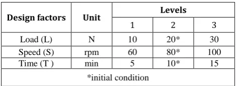
Table 2. Process parameters and their levels.
Design factors Unit Levels
1 2 3
Load (L) N 10 20* 30
Speed (S) rpm 60 80* 100
Time (T ) min 5 10* 15
*initial condition
To perform the experiments, the combinations given in Taguchi’s L27 OA (26 degrees of
freedom) are utilized since the degrees of freedom for the present experimental study is seen to be 18.
3.3 Coating characterization
Coating characterization is very important to ensure the deposit uniformity of the coatings and identify the morphological and microstructural changes occurring due to heat treatment, which in turn influences the tribological behavior of the deposits to a large extent. Composition study in terms of weight percentages of nickel, phosphorus and tungsten is done using energy dispersive X-ray (EDX) analyzer (FEI, FEG Quanta 250) for as-deposited and heat treated coatings. The phase transformation analysis is done using
an X-ray diffraction (XRD) analyzer (Rigaku, Miniflex) using Cu Kα radiation at a scan rate of 1°/min in as-deposited and heat treated condition to identify the compounds before and after heat treatment. Surface morphology of as-deposited as well as heat treated electroless Ni-P-W coating is done using scanning electron microscope (SEM) (JEOL, JSM 6360). SEM of a cross-cut section of heat treated Ni-P-W coating is also done to determine the coating thickness and compared with the highest value of wear depth that a specimen undergoes during the tribological tests. Finally, a worn out Ni-P-W coated surface is observed under SEM to determine the mechanism responsible for the wear of the deposits.
4. RESULTS AND DISCUSSION
4.1 Grey fuzzy reasoning
The values of wear depth and COF as obtained from the tribological tests are shown in Table 3. These values are further used to obtain the multi performance index representing both COF and wear depth which is the GFG in this study. The data obtained for wear depth and COF is first normalized based on lower–the–better criteria (Eqn. 2) since both of them are undesirable and needs to be minimized. From the normalized values, the GRCs for wear depth and COF are calculated using Eqn. 4.
The GRCs for wear depth and COF are fuzzified using triangular membership functions. Five fuzzy subsets, namely very small (VS), small (S), medium (M), large (L) and very large (VL) represent the GRCs for wear depth and COF (Fig. 1(a)). The output space is divided into nine fuzzy subsets i.e. tiny (T), very small (VS), small (S), small medium (SM), medium (M), medium large (M), large (L), very large (VL) and high (H) (Fig. 1(b)).
Table 3. Experimental data and calculation of GRC and GFG.
Exp. No.
Experimental
Data GRC GFG
Wear
(µm) COF Wear COF
1 5.031 0.1659 1 0.517 0.762
2 7.887 0.2221 0.732 0.429 0.57
3 10.196 0.2673 0.601 0.377 0.493
4 7.849 0.0804 0.734 0.75 0.739
5 9.486 0.0894 0.636 0.716 0.668
6 11.203 0.1147 0.558 0.635 0.603
7 12.649 0.0329 0.505 1 0.753
8 14.14 0.0355 0.461 0.982 0.709
9 15.407 0.0494 0.429 0.896 0.651
10 10.283 0.1353 0.597 0.581 0.601
11 11.134 0.1598 0.561 0.528 0.559
12 12.239 0.1653 0.519 0.518 0.532
13 9.55 0.1127 0.633 0.64 0.632
14 11.509 0.1236 0.546 0.611 0.588
15 12.866 0.1366 0.498 0.578 0.542
16 13.481 0.1179 0.48 0.626 0.548
17 16.816 0.1532 0.398 0.542 0.474
18 18.946 0.1655 0.359 0.517 0.444
19 10.979 0.2889 0.567 0.357 0.473
20 13.1 0.3045 0.491 0.344 0.418
21 14.088 0.3172 0.462 0.333 0.396
22 9.825 0.1373 0.619 0.577 0.606
23 13.718 0.1497 0.473 0.549 0.512
24 16.21 0.1559 0.411 0.536 0.476
25 17.318 0.1668 0.388 0.515 0.454
26 19.423 0.173 0.351 0.504 0.431
27 20.602 0.1755 0.333 0.499 0.42
Since the experimental design considered is orthogonal, it is very easy to obtain the mean value of GFG for a particular parameter at any given level. The mean GFG for the applied normal load, sliding speed and sliding time at their designated levels is laid down in Table 4 which is also called the response table. The mean GFG is also calculated. The table also contains ranks based on delta values. A delta value for each of the parameters is obtained by subtracting the lowest value from the highest one in each column. This value indicates the contribution of a
process parameter in controlling the response parameters. It is reflected from the results that load has the highest contribution followed by time and speed. The corresponding main effects plot is shown in Fig. 2. From the response table (Table 4) and main effects plot for GFG (Fig. 2), the optimum combination of parameters is seen to be L1S2T1 i.e. lowest value of applied normal load, mid value of sliding speed and lowest value of sliding time.
(a)
(b)
Fig. 1. Fuzzy subsets for (a) GRCs of wear depth and COF and (b) GFG.
Table 4. Response table for GFG.
Level L S T
1 0.6609 0.5338 0.6187
2 0.5467 0.5962 0.5477
3 0.4651 0.5427 0.5063
Delta 0.1958 0.0624 0.1123
Rank 1 3 2
Average value of GFG = 0.558
4.2 Confirmation test
A confirmation test is carried out to validate the result obtained for the optimization of wear depth and COF. The values of GFG obtained at the initial setting of the tribo – testing parameters i.e. L2S2T2 (mid value of the process parameters) and the one obtained at the optimum setting of the parameters (L1S2T1) are compared with a predicted value of GFG. The GFG at the optimal setting of the process parameters can be predicted using the following formula:
1
ˆ m o i m
i
(5)where
ˆ
is the predicted value of GFG,
m is the mean value of GFG for all the 27 experiments,
i is the mean GFG at the optimal level for each of the process parameters, and o is the number of main design parameters that significantly affect the wear and friction of electroless Ni-P-W coating.Table 5. Result of validation test.
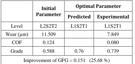
Initial Parameter
Optimal Parameter
Predicted Experimental
Level L2S2T2 L1S2T1 L1S2T1
Wear (µm) 11.509 7.849
COF 0.124 0.080
Grade 0.588 0.76 0.739
Improvement of GFG = 0.151 (25.68 %)
The validation run is carried out to determine if there is any improvement in GFG at the optimal condition compared to the initial setting of the design variables. Results for the confirmation test are shown in Table 5. It is seen that the predicted and experimental GFG are in close agreement. There has been an improvement of 25.68 % in the GFG at the optimum condition compared to the initial test levels. The wear depth and COF are seen to have reduced by a considerable amount. Hence, the optimal parameter settings can be justified as L1S2T1 (applied normal load of 10 N, sliding speed 80 rpm and sliding duration 5 min).
4.3 Analysis of variance (ANOVA)
ANOVA, an important statistical technique helpful in revealing the influence of process
parameters and their interactions in controlling the design variables, is carried out on the GFG. It separates the total variability of the responses into contributions of each of the factors and error [5,8]. The significance of a factor is determined by the F – ratio or the variance ratio. The F – ratio is the ratio of regression mean square to the mean square error. At a particular confidence level, if the obtained F – ratio for a factor is higher than the tabulated value, then it is considered to be significant at the same confidence level. The results of ANOVA performed on the GFG are tabulated in Table 6. It can be seen that at a confidence level of 97.5 % the applied normal load has the highest contribution in controlling the friction and wear of electroless Ni-P-W coating followed by sliding time and sliding speed. The interaction of load and speed is also seen to influence the response variables to some extent. The percentage contribution of each of the factors along with their interactions to the process is also enlisted in Table 6. Applied normal load is again seen to have the highest contribution of 57.67 % followed by sliding duration (19.25 %). The interaction of load and speed is also seen to be statistically significant.
A check of the deviation of data from normality is also done and the plot for the standardized residuals is shown in Fig. 3. It can be seen that the residuals fall on a straight line indicating that the errors are normally distributed. This validates the normality assumption and the independence of data and the adequacy of the ANOVA model is also tested. Thus, the proposed model can be considered to be adequate. In the present study, ANOVA results and residuals plot for GFG are obtained using Minitab software [44].
Table 6. Results of ANOVA.
Source DF SS MS F - Ratio % L 2 0.1741 0.0870 75.15* 57.67
S 2 0.0205 0.0103 8.87* 6.81
T 2 0.0581 0.0291 25.08* 19.25
L*S 4 0.0294 0.0074 6.35* 9.74
L*T 4 0.0074 0.0018 1.59 2.44
S*T 4 0.0031 0.0008 0.67 1.03
Error 8 0.0093 0.0012 3.07
Total 26 0.3019 100
Fig. 3. Normal probability plot for standardized residuals.
4.4 Composition, phase transformation,
surface morphology and microhardness
From EDX analysis, it is observed that as deposited Ni-P-W coated specimen is composed of 82.71 % Ni, 13.56 % P and 3.73 % W by weight. The weight percentage of phosphorus in the coatings indicates that the deposits fall in the high phosphorus category and the deposits are expected to be amorphous.
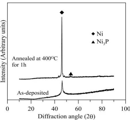
Fig. 4. X-ray diffraction plots for Ni-P-W coating in as-plated and heat treated (1h) condition.
XRD results reveal that as-deposited Ni-P-W coating is amorphous/nanocrystalline in nature (Fig. 4). The incorporation of tungsten improves the crystallinity of the coatings [33]. Hence a broad peak superimposed by a sharp peak of Ni is observed in the XRD plot in Fig. 4. It becomes crystalline on heat treatment due to the precipitation of nickel and its phosphides (Fig. 4). On heat treating the deposits in a furnace at 400 °C for 1 hr, the intensity of the Ni peak increases
and short peaks of stable Ni3P is visible in Fig. 4.
This is the indication of the crystalline and microcrystalline nature of the coatings on heat treatment. The crystallization temperature for binary Ni-P alloy system is 335 °C. Due to the incorporation of W in the alloy, the phase transformation temperature is raised with the precipitation of Ni3P and crystallization of Ni [17].
The phase transformation behavior observed in the present work agrees well with the theories proposed by other researchers [17,33]. A high value of hardness and consequently high wear resistance is observed in heat treated Ni-P-W coated specimens [16-22] due to the precipitation of phosphides and solid solution strengthening by Ni (W) on heat treatment.
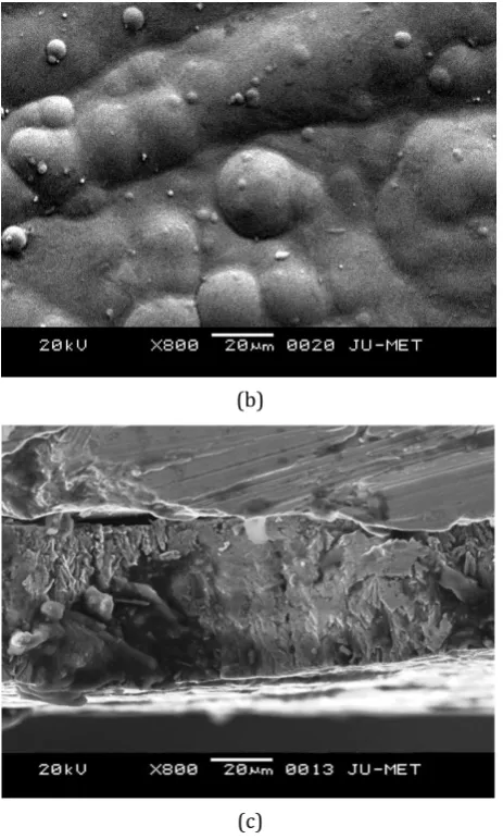
SEM micrographs of some coated specimens are taken in random in as-deposited and heat treated condition to analyze the effect of heat treatment on the surface morphology. Similar qualitative change is observed in all the specimens. SEM micrographs of an as-deposited and a heat treated sample are shown in Fig. 5(a) and Fig. 5(b) respectively. Nodulated structures can be observed on the coated surface in the SEM image of as-deposited coating (Fig. 5(a)). No visible surface damage or porosity can be observed and appears to be dense. The coating seems to become more compact on heat treatment (Fig. 5(b)). On heat treating the deposits at 400 °C, crystallization occurs, leading to the precipitation of Ni3P out of the
supersaturated solid solution of Ni as matrix containing P and W. Thus, volume contraction and a compaction of the EN matrix are observed. The globular surface morphology of the deposits is responsible for the inherent self lubricating nature of EN coatings and low COF [2,3].
(b)
(c)
Fig. 5. SEM image of Ni-P-W coating (a) as-plated, (b) heat treated at 400 °C (1h) and (c) cross-cut section.
A cross-cut section of Ni-P-W coating has been shown in Fig. 5(c). It is evident that the coating thickness is around 30 µm and the thickness is uniform. Since the bath composition is kept constant, the deposit thickness of all the coated specimens can be assumed to have nearly the same value. The highest value of wear encountered by a pin is seen to be 20.602 µm, which is less than the deposit thickness. Hence, it can be inferred that wear of the coatings only has taken place during the tribological tests and not the substrate material.
Microhardness of the as-deposited coatings is seen to be 678HV0.5 while it increases to
994HV0.5 on heat treatment. Microhardness of
EN coatings has a direct relationship with wear resistance. The coatings expectedly exhibit enhanced microhardness on heat treatment due to crystallization and phosphides precipitation. Though, heat treatment to a very high
temperature leads to deterioration of the tribological behavior of the coatings due to grain coarsening and softening of the deposits [16].
4.5 Analysis of wear mechanism
The wear mechanism is also investigated using SEM (Fig. 6). In the surface morphology of a worn surface, micro – cutting and ploughing effects are clearly visible. No pits or prows and detachment of the coating from the substrate are observed. Parallel grooves along the direction of sliding with high degree of plasticity can be seen which is indicative of ductile failure of the coatings and wear debris getting displaced to the sides of the wear track [8,12]. From the results, it can be assimilated that abrasive wear mechanism is predominant.
Fig. 6. SEM image of wear track of Ni-P-W coating.
In general, adhesive wear takes place in as – deposited EN coatings due to high mutual solubility of iron and nickel. But on heat treatment, precipitation of crystalline nickel and its phosphides takes place which can also be observed in the XRD analysis of heat treated Ni-P-W coating (Fig. 4). These phosphides have low mutual solubility with iron and present an incompatible surface to the steel counterface disc [16]. Hence, abrasive wear failure of the coatings is established.
4.6 Effect of process parameters on response
variables
contour plots in Matlab 7. In each of the plots, one parameter is kept constant at its mid level value and the variation is plotted against the other two parameters. The plots for wear depth and COF are depicted in Fig. 7 and Fig. 8 respectively.
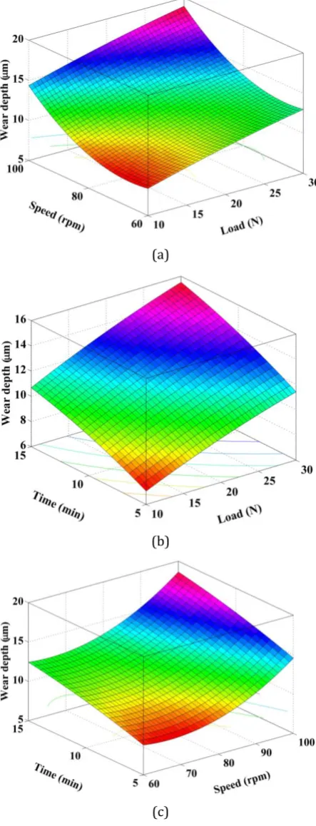
Effect of process parameters on wear depth: The effects of load, speed and time on wear depth are shown in Fig. 7. The plots reveal that the wear depth increases with the increase in load and speed (Fig. 7(a)). The specific wear rate of two mating surfaces depends on the actual contact area of the asperities. With the increase in applied normal load, the asperities on the coated surface and the counterface material advance more towards each other increasing the actual area of contact, thereby increasing the volume of material sheared. Hence, an increase in wear depth is observed. The wear depth is also seen to increase with the load time interaction (Fig. 7(b)). For a constant track diameter, with the increase in sliding speed or the sliding time, the sliding distance increases. This results in an increased wear of the coatings. The increase in wear depth with speed-time interaction (Fig. 7(c)) can also be attributed to the aforesaid reasons. The results obtained for the variation of wear depth with the lower ranges of tribo – testing parameters considered in the present study is in agreement with the ones obtained in previous studies [16] and is also in accordance with the relation given by Archard for the wear volume encountered by a material subjected to abrasive wear condition. Curvatures in the plot for wear depth vs. load, speed (Fig. 7(a)) and wear depth vs. speed, time (Fig. 7(c)) are seen indicating a low value of wear encountered by the coated specimen at mid – value of sliding speed. It can also be deduced from the Fig. 7(a), Fig. 7(b) and Fig. 7(c) that a lower wear of the deposits occurs at lower values of applied normal load and sliding time. Thus, the optimum combination of parameters for enhanced wear behavior i.e. L1S2T1 is justified. Low wear is suffered by the coatings on account of the high hardness obtained on heat treatment due to transformation of phase from amorphous to crystalline Ni and its phosphides (Fig. 4).
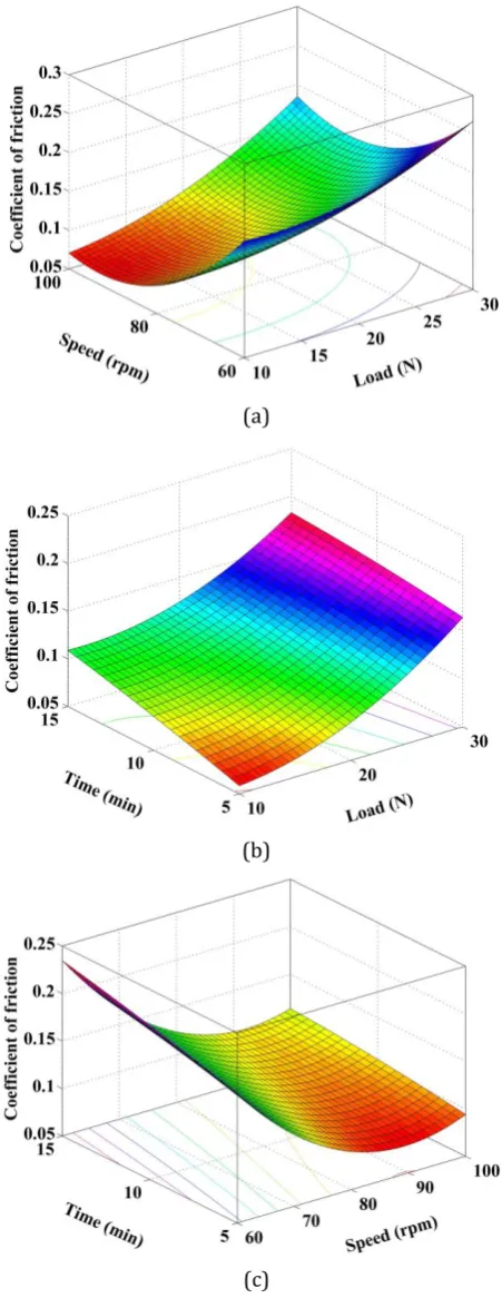
Effect of process parameters on COF: The COF is seen to be increasing with load and speed as well as load and time in Fig. 8(a) and Fig. 8(b) respectively. But with the increase in speed and
time, the COF is seen to decrease in Fig. 8(c). This can be attributed to the fact that EN coatings are self lubricating in nature due to their nodulated structure which is also visible in the SEM image of the as – plated and heat treated coatings (Fig. 5(a) and Fig. 5(b)).
(a)
(b)
(c)
(a)
(b)
(c)
Fig. 8. Surface plots showing the variation of COF vs. (a) load, speed, (b) load, time and (c) speed, time.
The aforesaid statements regarding the decreasing COF are again consolidated by the SEM micrograph of wear track (Fig. 6). It has already been established that abrasive wear condition prevails and adhesion is prevented since low heat is generated within the ranges of
the test parameters selected as well as the low solubility of the precipitated crystalline nickel phosphides with iron. Hence, electroless Ni-P-W coated specimen exhibits low COF. Again in Fig. 8(a) and Fig. 8(b), curvature is observed with low COF at mid – level value of speed. Thus, minimum COF is exhibited by the coated specimens at lower levels of load and time and mid level of speed, justifying the optimum combination of tribological testing parameters obtained using grey – fuzzy reasoning analysis. Thus, selection of operating conditions i.e. tribo testing parameters as well as the surface morphology and microstructure is seen to affect the tribological performance of the coatings.
5. CONCLUSION
The tribological behavior of electroless Ni-P-W coating under dry condition is investigated in the present work by following Taguchi’s L27 OA.
beneficial for selection of a potentially hard surface coating like Ni-P-W in applications requiring the reduction of friction and wear of mating surfaces working under non – lubricated environment.
Acknowledgement
The authors gratefully acknowledge the financial support of University Grants Commission (UGC), Govt. of India through Major Research Project vide Ref. No. F No. 41-984/2012 (SR) dated 25.07.2012.
REFERENCES
[1] A. Brenner and G.E. Riddell, ‘Nickel coating on steel by chemical reduction’, Journal of Research of National Bureau of Standards, vol. 37, no. 1, pp. 31–34, 1946.
[2] J. Sudagar, J. Lian and W. Sha, ‘Electroless nickel, alloy, composite and nano coatings–A critical review’, Journal of Alloys and Compounds, vol. 571, pp. 183-204, 2013.
[3] P. Sahoo and S.K. Das, ‘Tribology of electroless nickel coatings – A review’, Materials and Design, vol. 32, no. 4, pp. 1760-1775, 2011. [4] R.C. Agarwala and V. Agarwala, ‘Electroless
alloy/composite coatings: a review’, Sadhana, vol. 28, no. 3-4, pp.475–493, 2003.
[5] P. Sahoo, ‘Wear behaviour of electroless Ni–P coatings and optimization of process parameters using Taguchi method’, Materials and Design, vol.30, no. 4, pp.1341–1349, 2009. [6] B. Panja, S. K. Das and P. Sahoo, ‘Tribological
behavior of electroless Ni–P coating in brine environment’, Journal of the Institution of Engineers (India): Series D, vol. 95, no. 2, pp. 153-159, 2014.
[7] A. Mukhopadhyay, S. Duari, T.K. Barman and P. Sahoo, ‘Wear analysis of electroless Ni-P coating under lubricated condition using fuzzy logic’, Portugaliae Electrochimica Acta, vol. 34, no. 1, pp. 63-83, 2016.
[8] S.K. Das and P. Sahoo, ‘Tribological characteristics of electroless Ni-B coating and optimization of coating parameters using Taguchi based grey relational analysis’, Materials and Design, vol. 32, pp. 2228-2238, 2011.
[9] A. Mukhopadhyay, S. Duari, T.K. Barman and P. Sahoo, ‘Tribological performance optimization
of electroless Ni-B coating under lubricated condition using hybrid grey fuzzy Logic’, Journal of The Institution of Engineers (India): Series D, vol. 97, no. 2, 215-231, 2016.
[10] A. Mukhopadhyay, S. Duari, T.K. Barman and P. Sahoo, ‘Application of grey fuzzy logic for the optimization of tribological performance of electroless Ni-B coating’, Journal of Manufacturing Technology Research, vol. 7, no. 1-2, pp. 1-24, 2015.
[11] S. Duari, A. Mukhopadhyay, T.K. Barman and P. Sahoo, ‘Optimization of wear performance of electroless Ni-B coating under lubrication’, International Journal of Engineering and Technologies, vol. 7, pp. 94-103, 2016.
[12] K. Krishnaveni, T.S.N. Sankara Narayanan and S.K. Seshadri, ‘Electroless Ni–B coatings: preparation and evaluation of hardness and wear resistance’, Surface and Coatings Technology, vol.190, no.1, pp.115–121, 2005. [13] J.W. Jappes, B. Ramamoorthy and P.K. Nair,
‘Novel approaches on the study of wear performance of electroless Ni–P/diamond composite deposits’, Journal of Materials Processing Technology, vol. 209, no. 2, pp. 1004-1010, 2009.
[14] S. Alirezaei, S. M. Monirvaghefi, M. Salehi and A. Saatchi, ‘Wear behavior of Ni–P and Ni-P-Al2O3 electroless coatings’, Wear, vol. 262, no. 7, pp. 978-985, 2007.
[15] P. Gadhari and P. Sahoo, ‘Effect of TiO2 particles on micro-hardness, corrosion, wear and friction of Ni–P–TiO2 composite coatings at different annealing temperatures’, Surface Review and Letters, vol. 22, 1550082, 15 pages, 2015. [16] M. Palaniappa and S.K. Seshadri, ‘Friction and
wear behavior of electroless Ni–P and Ni–W–P alloy coatings’, Wear, vol. 265, no. 5, pp. 735-740, 2008.
[17] F. B. Wu, S.K. Tien, W. Y. Chen and J. G. Duh, ‘Microstructure evaluation and strengthening mechanism of Ni-P-W alloy coatings’, Surface and Coatings Technology, vol. 177-178, pp. 312– 316, 2004.
[18] S. Roy and P. Sahoo, ‘Optimization of electroless Ni-P-W coatings for minimum friction and wear using Grey-Taguchi method’, Journal of Coatings, vol. 2013, Article ID 608140, 13 pages, 2013. [19] S. Roy and P. Sahoo, ‘Tribological performance
optimization of electroless Ni‐P‐W coating using weighted principal component analysis’, Tribology in Industry, vol. 35, no. 4, pp. 297‐307, 2013. [20] A. Mukhopadhyay, S. Duari, T.K. Barman and P.
electroless Ni-P-W coating under dry and lubricated conditions using RSM and fuzzy logic’, Portugaliae Electrochimica Acta, vol. 34, no. 4, pp. 231-255, 2016.
[21] A. Mukhopadhyay, S. Duari, T.K. Barman and P. Sahoo, ‘Wear behavior of electroless Ni-P-W coating under lubricated condition – a Taguchi based approach’, IOP Conference Series: Materials Science and Engineering, vol. 149, Article ID: 012004, 10 pages, 2016.
[22] S. Roy and P. Sahoo, ‘Optimization of Wear of Electroless Ni-P-Cu Coating Using Artificial Bee Colony Algorithm’, Procedia Technology, vol. 14, pp. 320-327, 2014.
[23] Y. Xu, X. Zheng, X. Hu and T. Lei, ‘Preparation of electroless Ni-P and Ni-Cu-P coatings on engine cylinders and their tribological behaviours under bio-oil lubricated conditions’, Surface and Coatings Technology, vol. 258, pp. 790-796, 2014. [24] A. Ramalho and J.C. Miranda, ‘Friction and wear
of electroless NiP and NiP+PTFE coatings’, Wear, vol. 259, no. 7-12, pp. 824-834, 2005. [25] Z. Li, J. Wang, J. Lu, and J. Meng, ‘Tribological
characteristics of electroless Ni–P–MoS2 composite coatings at elevated temperatures’, Applied Surface Science, vol. 264, pp. 516-521, 2013.
[26] Y. Wu, B. Shen, L. Liu and W. Hu, ‘The tribological behaviour of electroless Ni-P-Gr-Sic composite’, Wear, vol. 261, no. 2, pp. 201-207, 2006.
[27] X.H. Chen, C.S. Chen, H.N. Xiao, H.B. Liu, L.P. Zhou, S.L. Li and G. Zhang, ‘Dry friction and wear characteristics of nickel/carbon nanotube electroless composite deposits’, Tribology International, vol. 39, no. 1, pp. 22-28, 2006. [28] F. Pearlstein, R. Weightman and R. Wick: Metal
Finishing, vol. 61, pp. 77–81, 1963.
[29] J.N. Balaraju and K.S. Rajam, ‘Electroless deposition of Ni-Cu-P, Ni-W-P and Ni-W-Cu-P alloys’, Surface and Coatings Technology, vol. 195, no. 2-3, pp. 154–161, 2005.
[30] J.N. Balaraju, C. Anandan, and K.S. Rajam, ‘Influence of codeposition of copper on the structure and morphology of electroless Ni-W-P alloys from sulphate- and chloride-based baths’, Surface and Coatings Technology, vol. 200, no. 12-13, pp. 3675–3681, 2006.
[31] J.N. Balaraju, S.M. Jahan, and K.S. Rajam, ‘Studies on autocatalytic deposition of ternary Ni-W-P alloys using nickel sulphamate bath’, Surface and Coatings Technology, vol. 201, no. 3-4, pp. 507–512, 2006.
[32] J.N. Balaraju, S.M. Jahan, C. Anandan, and K.S. Rajam, ‘Studies on electroless P and Ni-W-Cu-P alloy coatings using chloride-based bath’, Surface and Coatings Technology, vol. 200, no. 16-17, pp. 4885–4890, 2006.
[33] J.N. Balaraju, Kalavati, N.T. Manikandanath, V.K. William Grips, ‘Phase transformation behavior of nanocrystalline Ni–W–P alloys containing various W and P contents’, Surface and Coatings Technology, vol. 206, pp. 2682–2689, 2012. [34] H. Liu, R. X. Guo, and Z. Liu, ‘Effects of laser
nanocrystallisation on the wear behaviour of electroless Ni-W-P coatings’, Surface and Coatings Technology, vol. 219, pp. 31–41, 2013. [35] S.K. Das and P. Sahoo, ‘Wear performance
optimization of electroless Ni-B coating using Taguchi design of experiments’, Tribology in Industry, vol. 32, no. 4, pp. 17-27, 2010.
[36] S. Roy and P. Sahoo, ‘Multiple roughness characteristics of chemically deposited Ni-P-W coatings’, Tribology in Industry, vol. 34, no. 4, pp. 186-197, 2012.
[37] M. Kandeva, D. Karastoianov, B. Ivanova and V. Pojidaeva, ‘Influence of nano‐diamond particles on the tribological characteristics of nickel chemical coatings’, Tribology in Industry, vol. 36, no. 2, pp. 181‐187, 2014.
[38] O.O. Ajibola, ‘Evaluation of electroless-nickel plated polypropylene under thermal cycling and mechanical tests’, Tribology in Industry, vol. 38, no. 3, pp. 412-424, 2016.
[39] Y.-f. Tzeng and F.-c. Chen, ‘Multi – objective optimisation of high – speed electrical discharge machining process using a Taguchi fuzzy- based approach’, Materials and Design, vol. 28, pp. 1159-1168, 2007.
[40] A. Krishnamoorthy, S. Rajendra Boopathy, K. Palanikumar and J. Paulo Davim, ‘Application of grey fuzzy logic for the optimization of drilling parameters for CFRP composites with multiple performance characteristics’, Measurement, vol. 45, pp. 1286-1296, 2012.
[41] J.L. Deng, ‘Introduction to grey system theory’, Journal of Grey System, vol.1, no.1, pp. 1–24, 1989. [42] L.A. Zadeh, ‘Fuzzy sets’, Information and Control,
vol.8, pp.338–353, 1965.
[43] S.H. Żak: Systems and Control, Oxford University Press, New York, USA, 2003.