Published online April 30, 2014 (http://www.sciencepublishinggroup.com/j/jeee) doi: 10.11648/j.jeee.20140202.11
Optimization of motion adjustment pattern in intelligent
minesweeper robots (experimental research)
Yahya Hassanzadeh-Nazarabadi
1, Sanaz Taheri Boshrooyeh
2, Milad Bahrami
2, Danial Bahrami
3 1Mobile Robots Department, Parse Lab of Robotics, Mashhad, IRAN
2
Department of Computer Engineerign,Ferdowsi University, Park Sq, Mashhad, IRAN
3
Department of Computer Engineering, Semnan University, Semnan, IRAN
Email address:
[email protected](Y. Hassanzadeh-Nazarabadi), [email protected] (S. T. Boshrooyeh), [email protected] (M. Bahrami), [email protected] (D. Bahrami)
To cite this article:
Yahya Hassanzadeh-Nazarabadi, Sanaz Taheri Boshrooyeh, Milad Bahrami, Danial Bahrami. Optimization of Motion Adjustment Pattern in Intelligent Minesweeper Robots (Experimental Research). Journal of Electrical and Electronic Engineering.
Vol. 2, No. 2, 2014, pp. 36-40. doi: 10.11648/j.jeee.20140202.11
Abstract:
Nowadays, intelligent minesweeper robots have important roles in discovering, cleaning and defusing buried mines. Because of special conditions of mine detection operation, these robots should follow a very accurate and specified motion pattern. In this paper, prevalent methods of motion adjustment for minesweeper robots in an operational environment of mine field is studied experimentally and advantages and disadvantages of these methods are overviewed. Eventually, an experimental method, which eliminates problems of previous methods and has a high accuracy in motion adjustment is presented.Keywords:
Digital Compass, Encoders, Ultrasonic Sensors, Cartesian Coordination System1. Introduction
Iran is the third country in terms of buried mines in the world. More than 16 million mines were buried in border areas of west and south West of Iran during the eight year of war between Iran and Iraq. Because of inaccessibility to these places, some areas have non-defused mines and it has caused losses of many people and militaries for many years. Mine detection and defusing operation is very costly and dangerous. We hope that the minesweeper robots are effective in reducing costs, risks and casualties. Mine-sweeper robots must be able to detect, defuse or destroy mines in a specified area. Intelligent minesweeper robot, which is called ‘robot’ from now to end of this paper, operates automatically and without any human intervention on its control and decisions. The robot must detect mines with high speed and accuracy. By passing a mine detection sensor over a minefield, the entire area is scanned. The goal of this research is to develop an intelligent algorithms, which perform the defined tasks for robot precisely. A minesweeper robot must be able to move on an assumptive straight line during an operation. Certainly, due to the constraints of construction and environmental factors
during operation, it cannot be fulfilled. The most important reasons are: • Route friction
• Uneven route surface
• Non-uniform velocity of the robot wheels
To this day, several methods have been proposed to improve movement, such as:
• Motion adjustment by counter (Encoder) • Motion adjustment by compass (Compass)
particular circumstances, which has low probability of occurrence in current operations. So it does not degrade the accuracy of being operational for general purposes.
Thus, this paper, Section 2 describes the problem and assessed environment, then, in Section 3, the most common
approaches of motion adjustment in intelligent
minesweeper robots is described. In Section 4, the method implemented by the authors of this paper is expressed and finally, in Section 5, the results of this experimental research is announced
2. Problem Definition
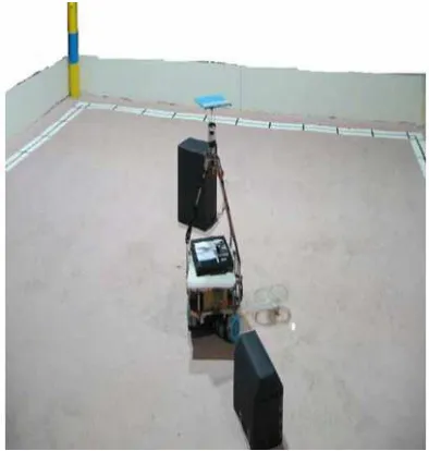
In this study, mine detection operations are performed in an environment described as below and illustrated in Figure1.
A land with dimensions of approximately 6* 8 meters made of gypsum cement and smooth as possible, however, since the conditions are not ideal, there might be slight bulge. Around the floor, there is a MDF (medium-density fiberboard) wall with 70 cm height. Its color is white and the floor is slight brown. From now and after, this operational environment is called Minefield [1].
Figure 1. Operational mind field.
There are two types of mines inside the minefield: buried mines and surface ones. Buried mines have the size and material of a can and are hidden in a depth of 30cm from the surface. Surface mines are covered up in the soil surface and part of their body is visible. The robot is obliged to detect buried mines and identify then displace surface mines [1].
Robot must start mine detection operation from a corner of the field and then continue to examine the whole ground, It also does not have the right to cross the barrier and it can only bypass them and if it reaches the wall (or crosses the white line) it will have to turn around and veer.
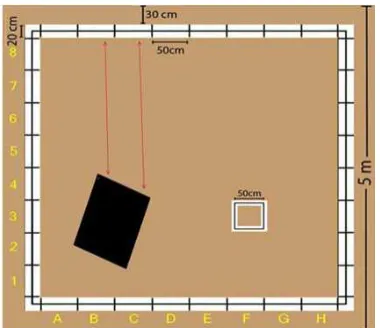
Operational minefield is divided into hypothetical
squares with dimensions of 50*50 Cm 2. According to patterns, there is only one mine in each square. Also minefield, as illustrated in Figure 2, is specified by English capital letters along the horizontal line and by numbers along the vertical line. For example, the small square displayed in Figure 2 is addressed with coordinates (A, 3). To evaluate the accuracy of the motion adjustment of the robot, 5 hypothetical points are placed in minefield and as the robot reaches them, it reports its coordinates. Correctness of a robot in motion adjustment is equal to the number of places where the coordinates calculated by the robot are equal to the original coordinates. By default, if we assume that robot starts to move from (A, 1), the order of the houses is as follows:
(B,8) , (D,8) , (F,8) ,(H,4) , (H,8)
Figure 2. Conventional segmentation of minefield.
3. Review of Common Methods in
Motion Adjustment
3.1. Ultrasonic Distance Assessment
Figure 3. Ultrasonic motion adjustment.
This method has several advantages:
• Reducing the problems of electronic
implementation: Due to adaptation of barrier detection system and motion adjustment system.
• Reducing the cost of robot manufacturing: be-cause
of the dual usage of ultrasonic system.
• No need to separate processing: by reason of the adaptation in previous cases, separate processing of input data or separate input processing area is not be required.
Main disadvantages of this method are:
• Reduction of robot’s accuracy even to 0% in
presence of barriers: When there are barriers in the field, They are placed between the robot and the wall during its movement, and when barrier is placed in front of it in a way that one of the sensors shows distance to the barrier and the other one shows distance to the front wall, The robot gets into trouble for detecting its distance from the walls and motion adjustment.
• Decrease in precision of the robot in case of
oscillation of minefield dimensions: Operational minefields do not have the same distance between the walls. For example, we can say it is shaped like a trapezoid. This thread can reduce the correctness of the robot.
• Inefficiency in cases with minefields having
dimensions greater than the range of ultrasonic sensors: If the operational minefield dimensions are greater than range of the robot sensors, the robot will not be able to detect walls as an index for mapping operation, so this method does not have the sufficient efficiency.
3.2. Motion Adjustment with Encoder
As shown in Figure 4, in this method, number of rounds taken by each wheel is denumerable by using an encoder on robot wheels. Coordinates of each wheel is calculated according to the mileage from the starting point [3, 5]. In order To put the robot in a straight line, the coordinates of
the wheels must be equal at any moment.
For adjusting the movement, two encoder values are compared in certain intervals.
If one of these two values is smaller than the other, it will represent the deviation of the robot to that side.
The processor increases the speed of that side to a certain value and reduces the opposite side’s speed. When values of two encoders become equal, the robot is placed in a straight line. At this time, the speeds become the same again.
One advantage of this method is its high overall accuracy. The precision of this technique is 67.25 percent, except in
special cases, which are described later. The
implementation of this routine is acceptably inexpensive and the robot’s mechanics and hardware are simpler than other existing methods.
One of the disadvantages of this method is progressive reduction of robot’s encoder accuracy in sequential rotations. Because rotations of these robots are in a differential arrangement [4]. As shown in Figure 5, during a spin, one engine’s speed is less than the other one. In this case, calculation of each encoder’s value and retrieval of their values after rotation are difficult and they require high accuracy measurements and large amount of calculations [7].
Figure 4. Encoder.
Figure 5. Differential arrangement.
3.3. Motion Adjustment by Compass
starts to move, the compass is calibrated and considers the robot’s angle with y axis as the origin angle. If the robot got deviated during its movement, the compass would report a nonzero angle between +90 and -90. At this time, the robot’s motion adjustment unit plans a rotation to right or left, based on the sign of the reported angel. This movement continues until the compass reports the angle is zero. The main advantage of this routine is the ease of implementation and high accuracy. In the absence of noise, motion adjustment precision of this method is 85.36%.
This technique has many drawbacks in operational implementation. In case of noise influence, the compass reports wrong angles and motion adjustment system is impaired. Also if the compass gets reset, it will become non-calibrated and the motion adjustment system will be damaged [6].
4. Local Motion Adjustment Technique
(Developed by the Authors)
In this method, there is a free ball on the underside of the robot. This ball is completely suspended and it is in full contact with the ground. The ball is in contact with two rods. As illustrated in Figure 6, these two rods, are assumed to be x and y axis. Each of them is connected to an encoder .Two dimensional coordinates of the robot are reported regularly during the movement.
Figure 6. Free ball and connected encoders.
Depending on the time limits of operation, a certain number of steps are determined for motion adjustment. Each step is equal to the assumed square in the problem description section (Squares with sides of 50 cm). Before each set of steps, the robot considers a point as endpoint. If the robot moves on a straight line, following the set of steps, it will reach to this endpoint. This point is known as the local adjustment point. After the set of steps, if the robot coordinates were not the same as coordinates predicted by the algorithm at the end point, then the robot is deviated. So the operation algorithm stops and the robot should go to predicted end point and adjust its motion. For example, we assume that the robot is at point A1 and the number of steps is 2. If the robot moves in the y axis as shown in Figure 2, it should stop after the second step and check its coordinates with coordinates of the endpoint predicted by
the algorithm (here (A, 3)) . The robot may be deviated. In this case the coordinates are different. To adjust the motion, operational algorithm of the robot stops and the robot goes to the point (A, 3), then operational algorithm continues.
The advantage of this method compared to other conventional approaches, is its high accuracy in operating conditions, this value was 92.33 percent in experiments. According to the technical reports of minesweeper robot teams and surveying the documentation of competitions, this correctness is unprecedented to this day. This technique doesn’t get influenced by noise. It doesn’t depend on the changes of dimensions of the operational field and it is independent to the robot’s motion pattern. Disadvantage of this routine is its monopoly to the presented model. According to this matter that its implementation depends on the length of steps, so for mentioned field, accuracy of this method for motion adjustment is 50 cm meaning that in-stead of considering the exact coordinates of the robot, motion adjustment unit considers its relative coordinates with respect to the difference between the squares. All points located on a square are identical for motion adjustment unit and the purpose of motion adjustment is reaching to the desired point or local adjustment point. While in the other conventional methods, the way of reaching and the way of placing the robot in that coordinates are important.
It is hypothesized that by reducing the length of each step, the accuracy of motion adjustment increases but it is not true, because by reduction of each step, size of local adjustment point decreases. In such conditions, by considering that the robot’s motion is not ideal, it's harder to reach the local motion adjustment point and probability of reaching to adjacent points of local point increases. Therefore, due to motion adjustment operation, the robot will have a long interval and it will prolong the mine detecting operation.
Considering that in mine detection operations,
assumption of dividing the land into the 50 cm squares is used, in comparison to all common methods, this technique has the highest operational accuracy in motion adjustment.
5. Conclusion
ac-curacy of this system is 92.33%. This method eliminates the disadvantages of common approaches. Drawback of this technique is its limitation to minefield’s proposed mod-el, which is described in problem definition section of this paper and its relative meaning of accuracy according to the same field. However, giving to operational conditions of minefields, it is concluded that the disadvantage of this technique compared to its unprecedented accuracy in motion adjustment is negligible.
References
[1] Technical Committee of Minesweeper Robots League, “Rules of the Intelligent Minesweeper Robots league”, 1th Robocup Iran Open Competitions, 2006, Tehran
[2] Y. Hassanzadeh-Nazarabadi, “Technical Document Paper of Parse Team”, 4th Robocup Iran Open competitions, Qazvin, 2009
[3] Y. Hassanzadeh-Nazarabadi, “Technical Document Paper of Parse Team”, 5th Robocup Iran Open competition, Tehran, 2010
[4] M.A. Sharif Shazile,” Technical Document Paper of Parse Team”, the second National Khwarizmi Robotic Competition, Tehran, 2009
[5] Y. Hassanzade-Nazarabadi, Nasim Yazdanpanah,” Intelligent Minesweeper Robot Algorithm design” The 1th National Conference on Software Engineering Applications”, Lahijan, 2008
[6] Y. Hassanzade-Nazarabadi,” Technical Document Paper of Parse Team”, 6th Robocup Iran Open Competitions, Tehran, 2011