Please cite this article as: A. Nandan, G. Singh,Experimental Study of Heat Transfer Rate in a Shell and Tube Heat Exchanger with Air Bubble Injection, International Journal of Engineering (IJE), TRANSACTIONS B: Applications Vol. 29, No. 8, (August 2016) 1160-1166
International Journal of Engineering
J o u r n a l H o m e p a g e : w w w . i j e . i r
Experimental Study of Heat Transfer Rate in a Shell and Tube Heat Exchanger with
Air Bubble Injection
A. Nandan*, G. Singh
Department of Mechanical Engineering, Chandigarh University, Ghauran, Mohali, Punjab, India
P A P E R I N F O
Paper history: Received 11 May 2016
Received in revised form 11 July 2016 Accepted 14 July 2016
Keywords:
Shell and Tube Heat Exchanger Heat Transfer Rate
Overall Heat Transfer Rate Dimensionless Exergy Loss
A B S T R A C T
Shell and tube heat exchangers are widely being used in many of industrial and power engineering applications. Different techniques have been employed in order to enhance the performance of the heat exchanger. Air bubble injection is one method to increase the turbulence of the flowing fluids which in turn enhance the heat transfer performance. Injecting air bubbles is one of the promising techniques which does not require much complex systems. Air can be injected at different points. In this paper, analysis has been carried out for heat transfer performance and exergy analysis with different air injection points. Four different cases with and without air injection in shell or tube side have been taken into consideration and the results are compared. Through the study, it has been observed that injecting air bubbles throughout the tube enhances the heat transfer rate by 25-40% at different range of the Reynolds Number. The effect of air injection at different points also affects the overall heat transfer and the dimensionless exergy loss.
doi: 10.5829/idosi.ije.2016.29.08b.16
NOMENCLATURE Subscripts
Ao Tube area (m2) avg Average
Cp Specific heat (J/kg K) C Cold side
E Exergy loss rate (W) E Environment condition
E Dimensionless exergy loss H Hot side
.
m Water mass flow rate (kg/s) I Inlet
Q Heat transfer rate (W) LMTD Logarithmic mean temperature difference
T Temperature min Minimum
U Overall heat transfer coefficient (W/m2K)
V Velocity (m/sec) Greek Letters
ρ Density (kg/m3)
µ Viscosity (Ns/m2)
1. INTRODUCTION1
The rising demand and limited source of energy extraction has lead the engineer to develop different techniques to enhance the performance of heat exchangers [1]. According to the World Energy Council, the rise in the energy demand due to industrialization and development will be around 50 - 80% by 2020 [2]. Heat exchangers are being widely
11*Corresponding Author’s Email: [email protected] (A.
Nandan)
used to conserve energy and to reuse this conserved energy for different purposes. The improved heat exchangers not only extract maximum possible energy, but also save the investment and the operating cost of the system [3].
Shell and tube heat exchangers are the commonly used heat exchangers due to their ability to withstand high pressure (up to 6000 psi) and temperature range (from -250 to 800oC) of the working fluid. They are being widely used in chemical and petrochemical industries, power plants, food processing industries, manufacturing, etc. The robust design, easy
maintenance and options for possible upgrades are the key features for their wide application.
Different techniques have been employed to enhance the performance of the shell and tube heat exchangers. One of the technique is to stimulate the heat transfer by providing turbulence. Air bubble injection can be considered as one of the techniques to stimulate the turbulence in the flow, and hence can be proved to be an efficient method in improving the performance of the heat exchanger. Different studies on the bubble dynamics suggests that the injection of air bubbles in the flow path reduces the shear stress and enhances the turbulence which enhances the heat carrying capacity of the heat exchanger.
Gabillet et al. [4] reported an enhancement in shear stress and turbulent kinetic energy with injection of air bubbles in turbulent boundary layers. Houshmand and Peles [5] experimentally studied the effect of air bubble flow rate with water flow rate on heat transfer characteristics in a micro channel and reported an enhancement of 16%. Celeta et al. [6] studied the effect of injection of air bubbles at the inlet of a heated channel and reported a 10 times enhancement in the heat transfer. Dizaji and Jafarmadar [7] reported an enhancement of 6-35% in Nusselt Number of a double pipe heat exchanger due to injection of air bubbles. Delaure et al. [8] reported an enhancement in heat flux due to the rising of an ellipsoid air bubble in water. Jacob et al. [9] studied the two phase flow and reported that shear stress and the Reynolds stress near the wall reduced with injection of air bubbles compared to that of single phase flow.
Kern [10] came up with the detailed design procedure of the shell and tube heat exchanger. Till today, various techniques have been employed to enhance the performance of the shell and tube heat exchangers such as providing tubulators, fins, different tube geometry, etc. Studies have been conducted on the effect of baffles spacing, baffle height and flow pattern on the effectiveness of shell and tube heat exchangers [11]. Nano fluids have also been introduced to enhance the performance of the heat exchangers [12].
The objective of this paper is to find out the effect of air bubble injection over the heat transfer characteristics in shell and tube heat exchangers. Earlier studies have been done with either double pipe heat exchangers or with vertically-placed shell and coiled tube heat exchangers. However, in industrial applications, mostly, shell and tube heat exchangers used have straight tubes and are placed horizontally. To the best of authors’ knowledge, studies over shell and tube heat exchanger with straight tubes have not been done. Since this is the most common heat exchanger being used, the effects of air injection is studied.
2. EXPERIMENTAL SETUP AND PROCEDURE OF
WORK
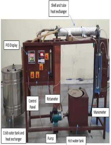
The schematic diagram of the experimental setup is shown in Figure 1, while Figure 2 shows the photographic representation of the experimental setup. The experimental setup consisting of test section, hot water loop, cold water loop and air injection system.
Figure 1. Schematic digram of experimental setup
Specifications of the test section is shown in Table 1. K-type thermocouples with an accuracy of 0.1oC were installed at the inlet and outlet of the shell and tube, and also on its wall surface to obtain the wall temperature.
Water is being heated in the five liter hot water tank. Proportional-integral-derivative (PID) controller is used to control the temperature of hot water. Hot water is pumped to the shell side at different flow rates (1, 1.5, 2, 2.5, 3 lpm) and at different temperatures (30, 40, 50 and 60oC). Cold water is pumped at a constant flow rate of 2 lpm and at a fixed temperature. Two flow meters each having an accuracy of about 1% were installed on the shell and tube side to control the flow rate on the shell side and tube side.
Accuracy and the range of the thermocouples, PID and the flow meter are described in Table 2.
Air was injected using an aquarium pump at the rate of 0.05833 kg/s having a negligible pressure compared to that created by the water flow at the ambient temperature of about 15oC.
The instruments were calibrated before test began. Experiments have been conducted in four different scenarios. The first group of experiments have been performed using hot distilled water on the shell side and cold distilled water on the tube side. Different readings have been noted down at five regular time intervals and average of the readings were taken for analysis.
After that, a plastic tube of very small diameter is inserted throughout the tube. The plastic tube has several very small holes. Hot water is being made to flow through the shell while cold water is made to flow through the tube and simultaneously air is injected in the tube side (see Figure 3). In the third set of tests, the it is injected at the shell entrance with the hot water.
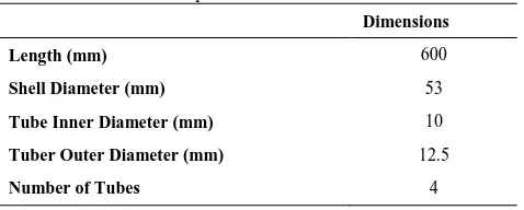
TABLE 1. Specifications of Test Section
Dimensions
Length (mm) 600
Shell Diameter (mm) 53
Tube Inner Diameter (mm) 10
Tuber Outer Diameter (mm) 12.5
Number of Tubes 4
TABLE 2. Accuracy of components Accuracy
Thermocouples 0.1 oC
Flowmeter 1%
PID 0.25%
It is made to mix properly before entering the shell and different readings have been noted down. In the fourth group of experiments, the air is being mixed with the cold water before entering the tube and different readings have been noted for data analysis.
3. DATA PROCESSING
To study the effect of air injection in the shell and tube heat exchangers, parameters such as overall heat transfer coefficient, heat transfer, exergy loss, and dimensionless exergy loss are calculated.
Reynolds Number is calculated using Equation (1).
(1)
The overall heat transfer coefficient is given by Equation (2).
(2)
The logarithmic mean temperature difference (TLMTD) is given by Equation (3).
(3)
The heat transfer rate is calculated using Equations (4)-(6).
(4)
̇ ( ) (5)
̇ ( ) (6)
The exergy loss and the dimensionless exergy loss has been calculated using Akpinar and Bicer [13] methods and Equations (7)-(11).
{ ̇
} (7)
{ ̇
} (8)
(9)
(10)
Cmin = Min {Ch and Cc} (11)
4. RESULTS AND DISCUSSIONS
The accuracy and the reliability of the system is tested with distilled water and different air injection methods, and the results have been compared.
4. 1. Effect on the Heat Transfer Rate The
quantity of heat transferred between hot and the cold fluid depicts the performance of any heat exchanger. The heat transfer rate takes place due to the difference of temperature between hot and cold side. From Equations (4) and (5), it has been observed that the more the temperature difference, the more will the heat transfer. From the experimental analysis, it has been observed that the heat transfer rate increases with the increase in the Reynolds Number. Injecting air at different points shown, enhances the heat transfer rate as compared to the situation without injection of air bubbles. Injecting air bubbles throughout the tube shows more enhancement as compared to the other methods due to the fact that the bubbles while rising up create a void which is filled by the nearby fluid. Earlier studies have proved that with more number of bubbles injected, higher heat transfer is obtained. So, injecting air throughout the tube increases the turbulence and hence carries more heat from the surface. Injecting air bubbles at the tube inlet along with water also enhances the heat transfer, but as compared to the previous case, it shows less enhancement. The reason behind this can be that the bubbles while rising creates more turbulence than the bubbles entering along with the water in the tube and injecting bubbles throughout the tube has more number of air bubbles than injecting at the tube inlet and thus less turbulence is created. Injecting air bubbles at shell inlet creates turbulence in the shell side and this enhances the heat transfer rate compared to the situation where no air is injected to any of the sides. From the results shown in Figure 2, it has been observed that injecting air bubbles throughout the tube enhances the heat transfer rate by 25-40% depending upon the Reynolds Number while injecting air at tube inlet enhances the heat transfer rate by 20-30% and injecting air bubble at the shell inlet enhances the heat transfer rate by 10-15% depending on the Reynolds Number (see Figure 4).
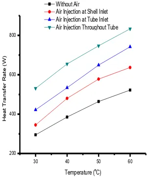
From Figure 5, it has been observed that at a constant flow rate of hot and cold water at 2 lpm, and with the increase in the hot water temperature, heat transfer rate increases. Due to increase in the temperature of the hot water, more will be the difference between hot and cold water and thus more heat will be absorbed by the cold water. The increase in the heat transfer rate is observed more in case of air injection. Air injected throughout the tube shows higher heat transfer rate as compared to other cases. It is followed by air injection at tube inlet and air injected at shell inlet. The case with no air bubble injection shows least enhancement with rise in hot water temperature than others.
4. 2. Effect on Overall Heat Transfer Coefficient
Overall heat transfer coefficient shows the conduction-convection resistance between the fluids.
5000 10000 15000 20000
200 400 600 800
H
e
a
t
T
ra
sf
e
r
R
a
te
(W
)
Reynolds Number Without Air Air Injection at Shell Inlet Air Injection at Tube Inlet Air Injection Throughout Tube
Figure 4. Reynolds Number Vs Heat Transfer Rate
30 40 50 60
200 400 600 800
H
e
a
t
T
ra
n
sf
e
r
R
a
te
(W
)
Temperature (o
C) Without Air Air Injection at Shell Inlet Air Injection at Tube Inlet Air Injection Throughout Tube
Increase in the Reynolds Number and injecting air bubbles enhances the overall heat transfer coefficient. From the results shown in Figure 6, it has been observed that injecting air bubbles throughout the tubes enhances the overall heat transfer coefficient by 30-45% than without air injection at different Reynolds Number as with number of bubbles injected, more turbulence is created and this in turn enhance the heat transfer capacity. The enhancement observed with air injection at tube inlet and shell inlet is 20-30% and 10-15% respectively compared to the without air injection based on different Reynolds Number. Injecting air bubbles at the tube inlet also creates turbulence and while moving forward with the flowing water, it creates a void which is filled by the surrounding water and thus they carry more heat from the surface. However, injecting air bubbles at shell inlet shows an enhancement by 10-15% as compared to without air injection as injecting air to the shell side that is on the hot side leds to transfer of more heat to the tube surface than the normal condition that is without any air injection.
From Figure 7, it has been observed that keeping constant flow rate of hot and cold water on shell side and tube side respectively that is 2 lpm, and increasing the temperature of the hot water, the overall heat transfer coefficient also increases. The rise in temperature leds to more temperature difference in the hot and cold water and thus more heat is transferred to the cold side. With injection of air bubbles the overall heat transfer coefficient has been observed even more compared to other cases. It is followed by air injection at the tube inlet and air injection at the shell inlet. The overall heat transfer coefficient without air injection shows least enhancement with increase in the temperature of the hot water.
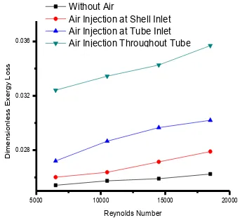
4. 3. Effect on Dimensionless Exergy Loss
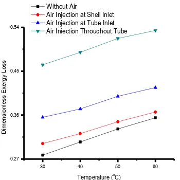
Exergy loss analysis is an important consideration in any heat exchanger. Exergy is the maximum useful work obtained by the system. For a better performance condition, maximum work should be obtained from the system. For a heat exchanger, the difference in the temperature is one of the cause of exergy distruction. Enhancement in dimensionless exergy loss shows that more amount of energy is being utilized from the system. From Figure 8, it has been observed that injecting air bubbles throughout the tube shows an enhancement by 35-45% followed by injecting air at the tube inlet which shows an enhancement by 20-30% and injecting air at the shell inlet which shows an enhancement by 10-15% depending on the range of the Reynolds Number. Injecting air at different points shows enhancement than without air injection and the different reasons behind them have been discussed earlier in section 4. 1 and section 4. 2. So, from Figure 6, it can be said that the air injection throughout the tube leds to maximum utilization of energy and hence the
cold water carries more heat from the surface. Figure 9 shows that with rise in temperature of the hot water and at constant flow rate of 2 lpm of hot and cold water, there is an enhancement in the dimensionless exergy loss. It has been observed that injection of air bubbles shows more enhancement in dimensionless exergy loss than without air injection.
5000 10000 15000 20000
200 400 600 800
O
ve
ra
ll
H
e
a
t
T
ra
n
sf
e
r
C
o
e
ff
ici
e
n
t
(W
/m
2
oC)
Reynolds Number
Without Air
Air Injection at Shell Inlet Air Injection at Tube Inlet Air Injection Throughout Tube
Figure 6. Reynolds Number Vs Overall Heat Transfer Coefficient
30 40 50 60
400 600 800 1000
O
ve
ra
ll
H
e
a
t
T
ra
n
sf
e
r
C
o
e
ff
ici
e
n
t
(W
/m
2K)
Temperature (oC)
Without Air
Air Injection at Shell Inlet Air Injection at Tube Inlet Air Injection Throughout Tube
Figure 7. Temperature Vs Overall Heat Transfer Coefficient
5000 10000 15000 20000
0.028 0.032 0.036
D
ime
n
si
o
n
le
ss
Exerg
y
L
o
ss
Reynolds Number
Without Air
Air Injection at Shell Inlet Air Injection at Tube Inlet Air Injection Throughout Tube
30 40 50 60 0.27
0.36 0.45 0.54
D
ime
n
si
o
n
le
ss
Exerg
y
L
o
ss
Temperature (oC) Without Air
Air Injection at Shell Inlet Air Injection at Tube Inlet Air Injection Throughout Tube
Figure 9. Temperature Vs Dimensionless Exergy Loss
5. CONCLUSIONS
From this study, followings conclusions have been made:
Air injection is one of the promising techniques in improvement of heat transfer performance. The heat transfer rate with air injection throughout
the tube shows an enhancement of 25-40% followed by air injection at the tube inlet which shows enhancement of 20-30% and at shell inlet which shows enhancement of 10-20% as compared to without any air injection at different Reynolds Numbers.
The overall heat transfer coefficient with air injection throughout the tube shows an enhancement by 30-45% followed by air injection at the tube inlet which shows enhancement by 20-30% and at shell inlet which shows enhancement of 10-15% as compared to without any air injection at different Reynolds Number.
The dimensionless exergy loss with air injection throughout the tube shows an enhancement of 35-45% followed by air injection at the tube inlet which shows enhancement by 20-30% and at shell inlet which shows enhancement by 10-15% as compared to without any air injection at different Reynolds Number.
Increase in the hot water temperature shows an enhancement in heat transfer rate, overall heat transfer rate and the dimensionless exergy loss. The enhancement is shown to be even more with
air injection throughout the tubes followed by air injection at the tube inlet and air injection at shell inlet.
6. REFERENCES
1. Kahrom, M., Haghparast, P. and Javadi, S.M., "Optimization of heat transfer enhancemnt of flat plate based on pereto genetic algorithm", International Journal of Engineering, Transaction A: Basics, Vol. 23, No. 2, (2010), 177-190.
2. Ahmadzadehtalatapeh, M. and Yau, Y.H., "Energy conservation potential of heat pipe heat exchanger: Exprimental study and predictions", International Journal of Engineering Transection B: Applications, Vol. 25, No. 3, (2012), 193-199. 3. Cancan, Z., Yafei, L., Li, W., Ke, X. and Jinxing, W., "Review
heat exchanger: Research development of self-rotating inserts in heat exchanger tubes", International Journal of Engineering-Transactions A: Basics, Vol. 27, No. 10, (2014), 15-26. 4. Gabillet, C., Colin, C. and Fabre, J., "Experimental study of
bubble injection in a turbulent boundary layer", International Journal of Multiphase Flow, Vol. 28, No. 4, (2002), 553-578. 5. Houshmand, F. and Peles, Y., "Impact of flow dynamics on the
heat transfer of bubbly flow in a microchannel", Journal of Heat Transfer, Vol. 136, No. 2, (2014).
6. Celata, G., Chiaradia, A., Cumo, M. and D’annibale, F., "Heat transfer enhancement by air injection in upward heated mixed-convection flow of water", International Journal of Multiphase Flow, Vol. 25, No. 6, (1999), 1033-1052.
7. Dizaji, S., "Heat transfer enhancement due to air bubble injection into a horizontal double pipe heat exchanger", International Journal of Automotive Engineering, Vol. 4, No. 4, (2014), 902-910.
8. Delauré, Y., Chan, V. and Murray, D., "A simultaneous piv and heat transfer study of bubble interaction with free convection flow", Experimental Thermal and Fluid Science, Vol. 27, No. 8, (2003), 911-926.
9. Jacob, B., Olivieri, A., Miozzi, M., Campana, E.F. and Piva, R., "Drag reduction by microbubbles in a turbulent boundary layer", Physics of Fluids (1994-present), Vol. 22, No. 11, (2010), 115104.
10. Kern, D.Q., "Process heat transfer, Tata McGraw-Hill Education, (1950).
11. Baghban, S.N., Moghiman, M. and Salehi, E., "Thermal analysisof shell-side flow of shell-and tube heat exchanger using experimental and the oretical methods", International Journal of Engineering, Vol. 13, No. 1, (2000), 15.
12. Aghabozorg, M.H., Rashidi, A. and Mohammadi, S., "Experimental investigation of heat transfer enhancement of fe 2 o 3-cnt/water magnetic nanofluids under laminar, transient and turbulent flow inside a horizontal shell and tube heat exchanger", Experimental Thermal and Fluid Science, Vol. 72, No., (2016), 182-189.
Experimental Study of Heat Transfer Rate in a Shell and Tube Heat
Exchanger with Air Bubble Injection
TECHNICAL NOTE
A. Nandan, G. Singh
Department of Mechanical Engineering, Chandigarh University, Ghauran, Mohali, Punjab, India
P A P E R I N F O
Paper history: Received 11 May 2016
Received in revised form 11 July 2016 Accepted 14 July 2016
Keywords:
Shell and Tube Heat Exchanger Heat Transfer Rate
Overall Heat Transfer Rate Dimensionless Exergy Loss