Data Communication &
Computer Networks
ACKNOWLEDGMENTS
Mostly adopted from lecture slides by Behrouz A. Forouzan.
Week 6: Course Plan
Multiplexing
FDM: Frequency Division Multiplexing
WDM: Wavelength Division Multiplexing TDM: Time Division Multiplexing
Multiplexing
It was impossible to get a conversation going,
everybody was talking too much. (
Yogi Berra)
This quote points to the issue of multiple simultaneous users
on a communications link.
Multiplexing allows several transmission sources to share a
Need for multiplexing
Capacity of transmission medium usually exceeds
capacity required for transmission of a single signal
If the bandwidth of a link is greater than the bandwidth
needs of the devices connected to it, the bandwidth is
wasted
So a medium linking two devices can be shared
Dividing a link into Channels
Multiplexing is a set of techniques that allows the simultaneous transmission of multiple signals across a single data link.
Multiplexer (MUX) combines multiple streams into a single
stream (many to one) and transmits over higher capacity data link
Demultiplexer (DEMUX) separates the stream back into its component transmission (one to many) and directs them to their correct lines.
n inputs to a multiplexer
a single data link
connects multiplexer and de-multiplexer
able to carry n separate channels of data
used to reduce the number of transmission media needed between cities and towns (to share an expensive resource)
Remember: Channel refers to the portion of a link that carries a transmission between a given pair of lines. One link can have many (n) channels
According to the
Encyclopedia of
Networking & Telecommunications
Multiplexing combines multiple channels of
information over a single circuit or
transmission path
In electronics
multiplexing allows several analog signals to be processed
by one analog-to-digital converter (ADC)
In telecommunications
Several phone calls may be transferred using one wire
In communications
the multiplexed signal is transmitted over a communication
Types of Multiplexing
Frequency-Division Multiplexing(FDM),
Wavelength-Division Multiplexing (WDM)
Time-Division Multiplexing(TDM)
Code-Division Multiplexing(CDM)
Frequency-division multiplexing (FDM)
A technique by which the total bandwidth available in a communication medium is divided into a series of non-overlapping frequency sub-bands,
each of which is used to carry a separate signal
Each signal is assigned a different frequency (sub-band) within
the main channel
It takes advantage of the fact that the useful
Frequency-division multiplexing
(FDM)
Channels can be separated by strips of unused bandwidth guard bands to
prevent signals from overlapping
Multiplexing process
a conceptual illustration of the multiplexing process (figure)
Each source generates a signal of a similar frequency range
Inside the multiplexer, these similar signals are modulated
onto different carrier frequencies (f1,f2 and f3)
The resulting modulated signals are then combined into a single composite signal that is sent out over a media link
De-multiplexing process
The de-multiplexer uses a series of filters to decompose the multiplexed signal into its constituent component signals
The individual signals are then passed to a demodulator that separates them from their carriers and passes them to the
waiting receivers (output lines)
FDM: Applications
Radio and television broadcasting
multiple radio signals at different frequencies pass
through the air at the same time
Cable television
many television channels are carried
simultaneously on a single cable
Telephone systems
Examples
Five channels, each with a 100-kHz bandwidth, are to be
multiplexed together. What is the minimum bandwidth of the link provided there is a guard band of 10 kHz between the channels to prevent interference?
For five channels, guard bands needed = 4
So required bandwidth is at least = 5 x 100 + 4 x 10 =540 kHz
Examples
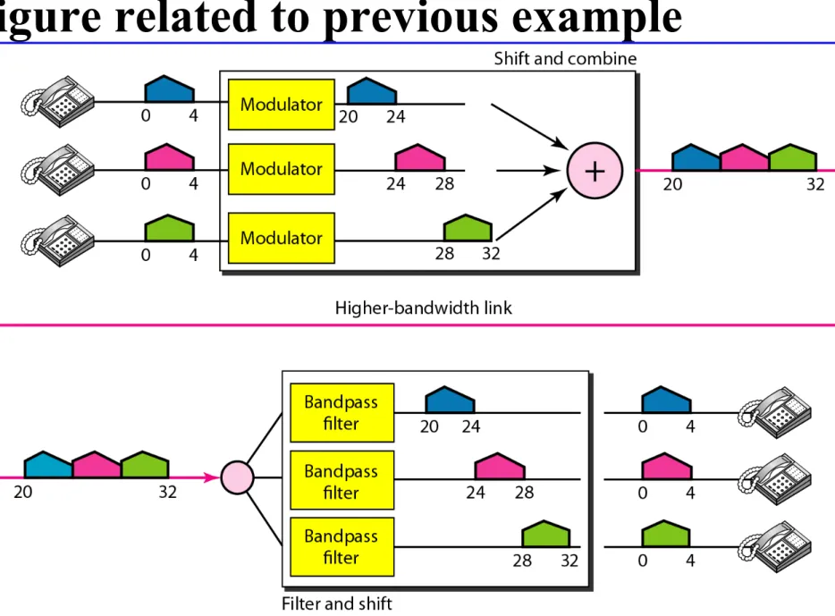
Assume that a voice channel occupies a bandwidth of 4 kHz. We need to combine three voice channels into a link with a bandwidth of 12 kHz, from 20 to 32 kHz. Show the configuration, using the frequency domain. Assume there are no guard bands.
Solution
We shift (modulate) each of the three voice channels to a
different bandwidth, then
Figure related to previous example
Other Applications of FDM
AM and FM radio broadcasting use air as the transmission medium
A special band from 530 to 1700 kHz is assigned to AM radio
each AM station needs 10kHz of bandwidth
FM has a wider band of 88 to 108 MHz because each station
Wavelength-division multiplexing
(WDM)
Designed to use the high-data-rate capability of fiber-optic cable
Which is higher than the data rate of metallic transmission cable
WDM is conceptually the same as FDM, except that
the multiplexing and de-multiplexing involve optical signals transmitted through fiber-optic channels
• The same idea: combining different signals of different frequencies
• The difference: the frequencies are very high
Wavelength-division multiplexing (WDM)
Basic idea: to combine multiple beams of light into one single light at the multiplexer (to make a wider band of light) and do the reverse at the de-multiplexer
Each colour of light (wavelength) carries separate data channel
The combining and splitting of light sources are easily handled
by a prism
Time-division Multiplexing
22
TDM is a digital multiplexing technique for combining several low-rate channels into one high-low-rate one.
In TDM, Instead of sharing a portion of the bandwidth as in FDM,
time is shared. Each connection occupies a portion of time in the link.
In the figure, portions of signals 1, 2, 3, and 4 occupy the link sequentially
Time-division multiplexing (TDM)
In TDM
each signal appears on the line only a fraction of
time in an alternating pattern
Each individual data stream is reassembled at the
receiving end based on the timing
TDM takes advantage of the fact that the
Time-division multiplexing (TDM)
In synchronous TDM
,
each input connection has an allotment in the output even if it is not sending data (time slot).
the data rate of the link that carries data from n connections
must be n times the data rate of a connection to guarantee the flow of data.
Time Slots and Frames:
In synchronous TDM, the data
flow of each input connection is divided into units, where
each input occupies one input time slot.
A unit can be 1 bit, one character, or one block of data. Each input unit becomes one output unit and occupies one output time slot.
However, the duration of an output time slot is n times shorter than the duration of an input time slot. If an input time slot is T s, the output time slot is T/n s, where n is the number of connections.
This implies that a unit in the output connection has a shorter
Interleaving
TDM can be visualized as two fast-rotating switches, one on the
multiplexing side and the other on the de-multiplexing side.
The switches are synchronized and rotate at the same speed, but in opposite directions.
Multiplexer/De-multiplexer process a terminal/host’s unit in turn. On the multiplexing side, as the switch opens in front of a
Interleaving
Character (byte) Interleaving: Multiplexing perform one/more character(s) or byte(s) at a time (one byte per unit)
Bit Interleaving: Multiplexing perform on one bit at a time (one bit per unit)
Empty Slots
Four channels are multiplexed using TDM. If each channel sends 100 bytes /s and we multiplex 1 byte per channel, show the frame traveling on the link, the size of the frame, the duration of a frame, the frame rate, and the bit rate for the link.
Solution
Each frame carries 1 byte from each channel; the size of each frame, therefore, is 4 bytes, or 32 bits. Because each channel is sending 100 bytes/s and a frame carries 1 byte from each channel, the frame rate must be 100 frames per second. The bit rate is 100 × 32, or 3200 bps.
A multiplexer combines four 100-kbps channels using a time slot of 2 bits. Show the output with four arbitrary inputs. What is the frame rate? What is the frame duration? What is the bit rate? What is the bit duration?
Solution
The link carries 50,000 frames per second. The frame duration is therefore 1/50,000 s or 20 μs. The frame rate is 50,000 frames per second, and each frame carries 8 bits; the bit rate is 50,000 × 8 = 400,000 bits or 400 kbps. The bit duration is 1/400,000 s, or 2.5 μs.
Data Rate Management
One problem with TDM is how to handle a disparity in the input data rates.
So far, we assumed that the data rates of all input lines were the same. However, if data rates are not the same, three strategies, or a combination of them, can be used. These three strategies
1. Multilevel multiplexing is a technique used when the data rate of an input line is a multiple of others. For example, here, we have two inputs of 20 kbps and three inputs of 40 kbps. The first two input lines can be multiplexed together to provide a data rate equal to the last three.
2. Multiple-Slot Allocation: Sometimes it is more efficient to allot more than one slot in a frame to a single input line.
3. Pulse Stuffing
Sometimes the bit rates of sources are not multiple integers of each other.
Therefore, neither of the above two techniques can be applied. One solution is to make the highest input data rate the
dominant data rate and then add dummy bits to the input lines with lower rates.
This will increase their rates.
This technique is called pulse stuffing, bit padding, or bit
stuffing.
The input with a data rate of 46 is pulse-stuffed to increase the rate to 50 kbps.
Frame Synchronizing :
Synchronization between theStatistical Time-Division Multiplexing
In synchronous TDM, each input has a reserved slot in the
output frame. This can be inefficient if some input lines have no data to send.
In statistical TDM, slots are dynamically allocated to improve bandwidth efficiency. Only when an input line has a slot's worth of data to send is it given a slot in the output frame.
In statistical multiplexing, the number of slots in each frame is normally less than the number of input lines.
The multiplexer checks each input line in round- robin fashion;
Statistical Time-Division Multiplexing
AddressingAn output slot in synchronous TDM is totally occupied by data; in statistical TDM, a slot needs to carry data as well as the
address of the destination.
In synchronous TDM, there is no need for addressing;
synchronization and pre-assigned relationships between the inputs and outputs serve as an address.
In statistical multiplexing, there is no fixed relationship between the inputs and outputs because there are no pre-assigned or
reserved slots.
No Synchronization Bit
Statistical Time-Division Multiplexing
Slot Size
Since a slot carries both data and an address in statistical
TDM, the ratio of the data size to address size must be
reasonable to make transmission efficient.
For example, it would be inefficient to send 1 bit per slot
as data when the address is 3 bits.
Statistical Time-Division Multiplexing
Bandwidth
In statistical TDM, the capacity of the link is normally less than the sum of the capacities of each channel.
The designers of statistical TDM define the capacity of the
link based on the statistics of the load for each channel.
If on average only x percent of the input slots are filled, the capacity of the link reflects this.
In TDM, a user sends at higher rate a fraction of
the time
In FDM, a user sends at low rate all the time
In analog transmission, signals are commonly multiplexed using FDM, in which
the carrier bandwidth is divided into sub-channels of different frequency widths, each carrying a signal at the same time in parallel
In digital transmission, signals are commonly multiplexed using TDM, in which
the multiple signals are carried over the same channel in alternating time slots.
In some optical fiber networks, multiple signals are carried
Code Division Multiplexing (CDM)
A narrowband signal is spread out over a wider frequency band
make it more tolerant of interference,
allowing multiple signals from different users to share the same frequency band (Code Division Multiple Access: CDMA)
CDMA allows each station to transmit over the entire
frequency spectrum all the time.
Code Division Multiplexing (CDM)
In CDMA, each bit time is subdivided into m short intervals called chips.
Typically, there are 64 or 128 chips per bit
Each station is assigned a unique m-bit code called a chip
sequence (sequences of −1 and +1in parentheses)
To transmit a 1 bit, a station sends its chip sequence.
To transmit a 0 bit, it sends the negation of its chip sequence.
Code Division Multiplexing (CDM)
For simplicity, consider 8 chips/bit as an example,
m =8
if station A is assigned the chip sequence
(−1 −1 −1 +1 +1 −1 +1 +1)
it can send a 1 bit by transmitting the chip sequence
and
a 0 bit by transmitting the negation of chip sequence (+1 +1 +1 −1 −1 +1 −1 −1).
Code Division Multiplexing (CDM)
Amount of information to be sent from
b
bits/sec
to
mb
chips/sec for each station
bandwidth needed for CDMA is greater by a
Code Division Multiplexing (CDM)
All chip sequences are pairwise orthogonal,
the normalized inner product of any two distinct chip sequences,
S and T (written as S .T), is 0.
Walsh codes are used to generate such orthogonal chip sequences.
Orthogonality of the chip sequences
S .T = 0, then is also 0
Code Division Multiplexing (CDM)
To recover the bit stream of an individual station
,
the receiver must know that station’s chip
sequence in advance.
Computes the normalized inner product of the
received chip sequence (
S
) and the chip sequence
of the station whose bit stream it is trying to
recover (
C
).
CDM Example