Effect of Tool Materials on Dynamic Friction Characteristics
and Microstructural Evolution at Elevated Temperature
in Extruded AZ31 Magnesium Alloy
Li-Fu Chiang
1;*, Noriaki Nishioka
1;*, Jian-Yih Wang
2, Hiroyuki Hosokawa
3,
Tokuteru Uesugi
1, Yorinobu Takigawa
1and Kenji Higashi
11Department of Materials Science, Graduate School of Engineering, Osaka Prefecture University, Sakai 599-8531, Japan 2Department of Materials Science and Engineering, National Dong Hwa University,
2-1, Da Hsueh Rd., Shoufeng, Hualien 97401, Taowan, R. O. China
3Materials Research Institute for Sustainable Development, National Institute of Advanced Industrial Science and Technology,
Nagoya 463-8560, Japan
The effect of the coating materials of the tools on the dynamic friction characteristics and microstructural evolution with straining was investigated by the ring-typed compressive test at a temperature of 473 K and at a strain rate of102s1in the extruded AZ31 magnesium alloy with an average grain size of 15mm. The values of the dynamically recrystallized grain size in the samples compressed up to about 45% by using the WC-Co tools with and without the DLC coating were 3.8mmand 4.8mm, respectively. The dominant deformation mechanism under all the testing condition for the present alloy was the climb-controlled dislocation creep. The dynamic friction coefficient,mvalue, for the sample compressed by the WC-Co tool was higher than that done by the DLC tool, even if though there was identical tendency in stress level. The integration degree of the grains within 10 degree fromh0001idirection to compressive axis in the sample compressed by the WC-Co tool was larger than that done by the DLC tool. It was concluded that the highermvalue could enhance an alignment of the planes perpendicular to the compressive direction to the basal plane even if under same testing condition. [doi:10.2320/matertrans.MBW200914]
(Received October 6, 2009; Accepted December 24, 2009; Published February 3, 2010)
Keywords: friction, magnesium alloy, compressive test, deformation mechanisms, dynamic recrystallization, crystal direction
1. Introduction
Plastic forming technologies for magnesium alloys have been developed, for example, the components with thin wall have been achieved without defect at the elevated temper-atures.1,2) The lower forming temperature has been much-needed in the engineering application field, as these forming temperatures are currently above 523 K.2–4) It is necessary to accumulate the sufficient data about magnesium forming technologies at the temperatures below 523 K.
Friction characteristics between the deformed materials and the tools are some of the essential factors for the plastic forming technologies. Koga and Paisarn5)indicated that the formability for AZ31 magnesium alloy was almost same to those for steel and aluminum alloy as a result of low friction coefficient. Takara et al.4) indicated that the low friction might cause surface defect by material overflow from an opposite side of rib in rib forging. The data of the friction characteristics by using the ring-typed compressive test have been reported for magnesium alloys4,6–8)and indicated that lubricant drastically influence to friction characteristics and lubricant was required for lower friction at 473–623 K.
Very recently, authors8)investigated comprehensively the friction characteristics of the magnesium alloy above 523 K and suggested that not only external factors, that was, lubricant and surface materials of the tool, but also internal factors, that was, grain size and crystal orientation, influenced to the dynamic friction coefficient. It is necessary for achievement of the plastic forming technologies at the lower region in high temperatures to investigate them below the
temperatures in the previous work. A purpose of this study is to investigate them at 473 K from the view of the better industry applications.
2. Experimental Procedures
The material used in this work is an extruded AZ31 magnesium alloy. The microstructures before/after testing were observed by optical microscope, scanning electron microscope (SEM) with electron backscatter diffraction (EBSD), besides, the microstructures after testing were observed transmission electron microscopy (TEM). The grain size,d, was determined byd¼1:74L, whereLis the linear intercept size. The boundaries with misorientation angle more than 5 degree were regarded as grain boundaries on the EBSD maps. Though the observed areas were in proximity the surface on cross section area perpendicular to extruded direction or compressive axis, the EBSD maps show the crystallographic orientation analyzed from the direction parallel to extruded direction or compressive axis.
The dynamic friction coefficient (mvalue) was determined by employing the ring-typed compressive test on ZENFormer servo press machine with furnace. The m value was determined by comparison of the experimental results and Male’s calibration curve.9)The mvalues are determined by between compressibility ratio,Re, and reduction rate of inner diameter,E, which are given by:
Re¼Hh
H ð1Þ
E¼Didi
Di
ð2Þ *Graduate Student, Osaka Prefecture University
whereHis the initial height of specimen,his the height of specimen after ring compression test, Di is the initial inner diameter of specimen and di is the inner diameter of specimen.
The ring specimens with 4 mm in height, 6 mm in inner diameter and 12 mm in outside diameter were machined from the extruded bars by the electro-discharge method, where the angle between the compressive direction and the extruded direction was 0 degree.
The two kinds of the materials for surfaces of the tools were prepared; WC-Co cemented carbide and the diamond like carbon (DLC) (hereafter referred to as WC-Co and DLC tools, in addition, the samples compressed by WC-Co and DLC tools are called the samples by WC-Co and by DLC, respectively). The mean surface roughness,Ra, was measured by color laser 3D profile microscope.Raof WC-Co and DLC tools were 0.03mmand 0.04mm. The commercial oil-based lubricant (S-5996) was used in this work. The samples were deformed up to given strains around 45% at a temperature of 473 K and at a strain rate of102s1.
3. Deformation Mechanisms
Authors indicated that the deformation mechanisms of the magnesium alloy influenced to the dynamic friction coef-ficient at elevated temperatures, and magnesium alloys had possibility to change the deformation mechanisms during high temperature deformation due to the dynamic recrystal-lization (DRX).8)Therefore, the estimation of the deforma-tion mechanisms all the while testing should be required.
In general, the constitutive equation for deformation at elevated temperature is expressed as:10)
_ "
"¼A Gb kT b d p th G n
D ð3Þ
where ""_ is the strain rate, A is a constant, G is the shear modulus {¼E=ð2 ð1þÞÞ, E is the Young’s modulus
[¼4:3104 ð15:3104 ðT300ÞÞ],is Poisson’s ratio and T is the absolute temperature}, b is the Burgers vector, k is the Boltzmann’s constant, d is the grain size,
p is the grain size exponent, is the flow stress, th is the threshold stress,nis the stress exponent andDis the diffusion coefficient {¼D0expðQ=RTÞ: D0 is the pre-exponential factor for diffusion,Ris the gas constant,Qis the activation energy}.
The magnesium alloys have three modes of the deforma-tion for the possible mechanisms in the strain rate range for plastic forming: (a) slip accommodated grain boundary sliding process, which is accepted as the dominant deforma-tion mechanism for superplastic flow,11–13) (b) glide con-trolled dislocation creep14)and (c) climb controlled disloca-tion creep.15)The constitutive equations for each deformation are expressed as:
_ "
"¼1:8106 Gb
kT b d 2 th G 2
DLþ1:7102
d Dgb
ð4aÞ
_ "
"¼3:0102 Gb
kT
th
G
3
Ds ð4bÞ
_ "
"¼8:0104 Gb
kT
th
G
5
DLþ2:0109
G
2
Dgb !
ð4cÞ
where DL is the diffusion coefficient for the lattice (¼1:0104expð135000=RTÞ), is the grain boundary width ( was taken to be2b in the present analysis),Dgb is the diffusion coefficient for the grain boundary (¼5:0
1012expð92000=RTÞ) and D
s is the diffusion coefficient for the solute atom (¼1:2103expð143000=RTÞ).
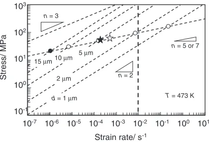
The relationship between the flow stress and the strain rate for magnesium alloys at 473 K is shown in Fig. 1, where the diffusion coefficient and shear modulus of AZ31 magnesium alloy were taken to be those of pure magnesium. Due to independence for each mechanism, the fastest mechanism appears deformation behavior for the materials. It is noted that grain size less than 2mm is required to behave
super-plastic deformation at 473 K and 102s1 for AZ31 magnesium alloy.
4. Results and Discussion
An optical microphotograph and the EBSD map of the extruded AZ31 magnesium alloy are shown in Fig. 2. The material has almost equiaxed grains but a few elongated grains paralleled to extruded direction. The fraction of the boundaries with rotation angle more than 15 degree is 0.7, then an average grain size is 15mm. It is interesting to note that the deformation mechanism at 473 K and102s1in the present alloy with the grain size is corresponded to a region
10-7 10-6 10-5 10-4 10-3 10-2 10-1 100 101 Strain rate/ s-1
Stress/ MPa
n = 3
T = 473 K
n = 2
n = 5 or 7
10-1 100 101 102 10
d = 1 µm 5 µm 15 µm 10 µm
2 µm
Fig. 1 The relationship between flow stress and strain rate for slip accommodated grain boundary sliding process (n¼2), glide-controlled dislocation creep (n¼3), and climb controlled dislocation creep (n¼5or 7) at 473 K, where the open and close circles indicate the transition point of the deformation mechanisms for various grain sizes, the open and the close star marks indicate those for the DRX grain sizes of the samples tested by WC-Co and DLC tools. The dash line perpendicular to X-axis indicates
[image:2.595.322.532.72.215.2]characterized by the climb-controlled dislocation creep (see the close circle in Fig. 1). It is also noted that the (10-10) plane is perpendicular to the extruded direction and the compressive axis.
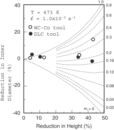
The comparison between the measured data and the calibration curves for friction coefficient (mvalue) is shown in Fig. 3. The measured data for the samples by WC-Co and DLC were approximately fitted the curves of 0.3 and 0.2, respectively, that is, the m value for sample by WC-Co is higher than that for sample by DLC. This trend is same as the
previous work above 523 K.8)The stress for the sample by WC-Co (166 MPa) was slightly higher than that for the sample by DLC (156 MPa).
Optical microscopes of the samples after testing at 473 K and102s1 are shown in Fig. 4. It is found that both the samples after testing have the fine grain size little less than the initial grain size at 15mm, namely, DRX caused during the compressive flow. The average grain sizes after DRX are 3.8mmand 4.8mmfor the samples by WC-Co and by DLC respectively. These grain sizes are disagreement with the expected DRX grain size of 0.7mmfrom the equation derived by Watanabeet al.,16)taking an effect by the initial grain size into the consideration. However, these values are good agreement with the estimation reported very recently by Takigawa et al.17) The transition points of the deformation mechanisms for the DRX grain sizes are also superimposed on Fig. 1 as the star marks. It is noted that the AZ31 magnesium alloy unalterably indicates the climb controlled dislocation creep during compressive testing at 473 K and
102s1.
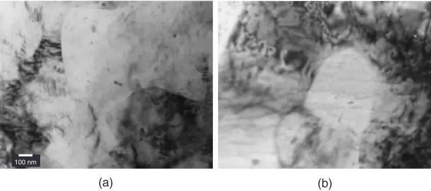
TEM micrographs of the samples operated by both tools of WC-Co and DLC at 473 K and102s1are shown in Fig. 5. There were observed a lot of the dislocations in both samples. In addition, there are fine particles in both the samples, speculating that these are Mg17Al12.18,19) It might be considered that these particles play an effective role as pinning to stabilize the structures after DRX even if at an elevated temperature of 473 K.
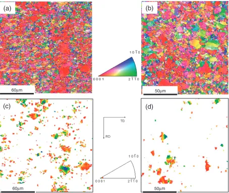
The EBSD maps are shown in Fig. 6 for the samples operated to the strain around 45 % at 473 K and102s1by the tools of WC-Co and DLC. It is clearly found from Fig. 6(a) and (b) that the crystal plane perpendicular to compressive axis varies from (10-10) plane to (0001) plane during compressive testing. Its tendency in the sample by
20
µµ
m
(a)
100
µ
m
(b)
Fig. 2 An optical microphotograph (a) and the EBSD map (b) of the extruded AZ31 magnesium alloy. The extruded direction is vertical.
Reduction in Height (%) Reduction in Inner Diameter (%)
0.4
0.3
0.16 0.2
0.12
0.08
0.04 0.02 m = 0
0.6
40
20
0
-20
-40
50 40 30 20 10 0
WC-Co tool DLC tool
1.0 0.8
T = 473 K ε. = 1.0x10⁻² s-1
Fig. 3 Calibration curves including experimental results at 473 K and
[image:3.595.82.514.69.341.2] [image:3.595.70.268.387.614.2]WC-Co is stronger than that in the sample by DLC. In the focus of the crystal direction (see Fig. 6(c) and (d)), the ratio of theh0001idirection oriented parallel to the compressive axis for the sample by WC-Co is higher than that for the sample by DLC, indicating that the materials flow of the sample by the WC-Co is harder than that of the sample by DLC at an elevated temperature of 473 K. It might be considered that this trend results in the higher interactive restraining-force (or binding-force) between the interfaces of the materials and the tools to the materials flow attributed to highermvalue for the sample by WC-Co.
5. Conclusions
The dynamic friction characteristics by the ring-typed compressive test with two different materials of the tool surface (i.e., WC-Co and DLC) were investigated for the extruded AZ31 magnesium alloy and also the observation of the microstructural evolution with compressive straining to around 45% was carried out at an elevated temperature of 473 K and a strain rate of 102s1. The grain was refined from an initial size of 15mmto the dynamically recrystallized
grain size of less than 5mm in both the samples tested by WC-Co and DLC tools. From the judgment by grain size dependency on deformation mechanisms, the dominant deformation mechanism of the current magnesium alloys was the climb controlled dislocation creep under the condition with102s1 and 473 K. As far asmvalues were concerned, the value obtained from the sample by WC-Co was higher than that from the sample by DLC. There was identical tendency in stress level even if the stress of the sample by WC-Co was slightly higher than that of the sample by DLC. The crystal planes perpendicular to compressive direction aligned to the basal plane through compressive testing for both the samples. The number of the grains within maximum 10 degree from h0001i direction to compressive axis for the sample by WC-Co was larger than that for the sample by DLC.
Acknowledgements
This work was partly supported by the Chian Hsing Forging Industrial Co., LTD (Taichung). The authors thank to Kasatani Corp. for supplying lubricant.
(a)
(b)
10 µm 10 µm
Fig. 4 Optical microstructures of the samples tested at 473 K and102s1by WC-Co tool (a) and DLC tool (b).
(b)
(a)
100 nm
[image:4.595.85.511.72.250.2] [image:4.595.86.509.297.485.2]REFERENCES
1) T. Shimizu: Alutopia31(2001) 41–44.
2) H. Okahara, M. Ohara, Y. Takigawa and K. Higashi: Mater. Trans.47
(2006) 954–958.
3) A. Takara, Y. Nishikawa, H. Watanabe, H. Somekawa, T. Mukai and K. Higashi: Mater. Trans.45(2004) 2531–2536.
4) A. Takara, Li-Fu Chian, S. W. Chung, H. Somekawa, H. Watanabe, Y. Takigawa and K. Higashi: Mater. Trans.49(2008) 898–902. 5) N. Koga and R. Paisarn: J. Jpn. Soc. Technol. Plast.42(2001) 145–149. 6) T. Male and M. G. Cockcroft: J. Inst. Metals93(1964-65) 489–494. 7) K. Chen, T. B. Huang and S. G. Chen: Int. J. Adv. Manuf. Technol.32
(2007) 272–279.
8) L.-F. Chiang, H. Hosokawa, J.-Y. Wang, T. Uesugi, Y. Takigawa and K. Higashi: J. Jpn. Soc. Technol. Plast.49(2008) 901–905. 9) A. T. Male and M. G. Cockcroft: J. Inst. Metals93(1964–1965) 38–46. 10) H. J. Frost and M. F. Ashby: Deformation-mechanism Maps,
(Pergamon Press, 1982) 44–45.
11) H. Watanabe, T. Mukai, M. Kohzu, S. Tanabe and K. Higashi: Acta Mater.47(1999) 3753–3758.
12) H. Watanabe, T. Mukai, M. Ishikawa, M. Mabuchi and K. Higashi: Mater. Sci. Eng. A307(2001) 119–128.
13) H. Watanabe, T. Mukai, M. Mabuchi and K. Higashi: Acta Mater.49
(2001) 2027–2037.
14) H. Watanabe, H. Hosokawa, T. Mukai and T. Aizawa: Materia Japan
39(2000) 347–354.
15) H. Somekawa, H. Watanabe, T. Mukai and K. Higashi: Mater. Sci. Forum426–432(2003) 605–610.
16) H. Watanabe, H. Tsutsui, T. Mukai, K. Ishikawa, Y. Okanda, M. Kohzu and K. Higashi: Mater. Trans.42(2001) 1200–1205.
17) Y. Takigawa, M. Honda, T. Uesugi and K. Higashi: Mater. Trans.49
(2008) 1979–1982.
18) J. P. Zhou, D. S. Zhao, R. H. Wang, Z. F. Sun, J. B. Wang, J. N. Gui and O. Zheng: Mater. Lett.61(2007) 4707–4710.
19) K. Ma´this, J. Gubicza and N. H. Nam: J. Alloy. Compd.394(2005) 194–199.
(b)
(c)
50µm
60µm
(a)
60µm
(d)
50µm
[image:5.595.72.526.71.455.2]