Dynamic Friction Properties and Microstructural Evolution
in AZ31 Magnesium Alloy at Elevated Temperature
during Ring Compression Test
Noriaki Nishioka
*, Li-Fu Chiang
*, Tokuteru Uesugi, Yorinobu Takigawa and Kenji Higashi
Department of Materials Science, Osaka Prefecture University, Sakai 599-8531, Japan
The dynamic friction properties of the extruded AZ31 magnesium alloy with the initial average grain size of 15mmwere investigated by
the ring compression test at 473 and 523 K and in a strain rate range from1:0102to 3.0 s1. Two types of the tool, WC-Co tool (WC) and
WC-Co coated with diamond like carbon tool (DLC) were used. At 523 K, few differences in terms of the friction coefficient were observed due to the difference with or without DLC. At 473 K, the friction coefficient for the sample deformed by DLC tool was smaller than that done by WC tool. The investigation of the texture near the surface of the tested work pieces with different tools reveals that the integration degree of the grains
within 10 degree fromh0001idirection to compressive axis in the sample deformed by the DLC tool was smaller than that done by WC tool. It
was concluded that the larger friction could enhance alignment of the planes perpendicular to the compressive direction to the basal plane even if
under same testing condition. [doi:10.2320/matertrans.MC201013]
(Received December 28, 2010; Accepted May 2, 2011; Published June 22, 2011)
Keywords: magnesium, friction, forging, tool materials, ring compression test
1. Introduction
Magnesium alloys are used for many components of mobile electric appliances such as cellular phones and notebook computers. This is because magnesium alloys have high specific strength and high specific rigidity. On the other hand, magnesium alloys have low formability due to limited slip systems at room temperature. Thus, hot or warm deformation processes are necessary to increase the form-ability of the alloys. Recently, plastic forming technologies for magnesium alloys have been developed, for example, the components with thin wall have been achieved without defect.1)
For plastic forming process, interactive friction property between the deformed materials and the tools is one of the important factors, because formability is strongly affected by it. In order to solve the lubricant-related problems, it is very important to understand the friction between die and work piece and to control it. Koga and Paisarn2)have reported that the formability of AZ31 magnesium alloy is almost the same to those for steel and aluminum alloys as a result of low friction coefficient. Takara et al.3) indicated that the low
friction might cause surface defect in rib forging by material overflow from the opposite side of the rib. The data of the friction characteristics by using the ring-typed compressive test have been reported for magnesium alloys in a temper-ature range of 473–623 K3–7) and have indicated that
lubricant drastically influences to the friction characteristics. However, the relationship between the friction characteristics and the microstructural evolution has not been investigated so much.
In the previous work in our group,8) we investigated comprehensively the friction characteristics of the magne-sium alloy above 523 K and suggested that not only external factors, that was, lubricant and surface materials of the tool,
but also internal factors, that was, grain size and crystal orientation, influenced to the dynamic friction coefficient. It is necessary for the achievement of the plastic forming technologies at lower temperatures to investigate the friction characteristics below the temperatures in the previous work. Recently, authors reported the effect of the coating materials of the tools on the dynamic friction characteristics and the microstructural evolution with straining by the ring-typed compressive test at a temperature of 473 K and at a strain rate of 102s1 in an extruded AZ31 magnesium alloy.9)
However, the test condition is limited and it is necessary to investigate them at several conditions especially at higher strain rate from the view of the better industry applications. In the present study, we investigated the dynamic friction properties of AZ31 magnesium alloy in a wide range at temperatures of 473 and 523 K and strain rates of102,101,
1 and 3 s1.
2. Experimental Procedure
2.1 Measurement of the friction coefficient by ring compression test
Among all common methods for measuring the friction coefficient, the ring compression test has gained wide acceptance. This technique utilizes the dimensional changes of a test specimen. For given percentage of height reduction during compression test, corresponding measurement of inside diameter of the test specimen provides a quantitative knowledge of the magnitude of the prevailing friction coefficient at the die/work piece interface. When the inside diameter of the specimen increase during the deformation, friction is low. When the inside diameter of the specimen decrease during the deformation, friction is high. Using the change in the relationship between the reduction in the inside diameter and the reduction in height of the test specimen for varying degrees of friction coefficient, friction calibration curves were generated by Male and Cockcroft. Friction
*Graduate Student, Osaka Prefecture University
coefficient was determined by comparison of the experimen-tal results and Male’s calibration curve.10) Friction coeffi-cients are determined by the relationship between the reduction ratio of height,Re, and the reduction ratio of inner
diameter,E, which are given by:
Re¼
Hh
H ð1Þ
E¼Didi
Di
ð2Þ
whereHis the initial height of specimen,his the height of specimen after ring compression test, Di is the initial inner
diameter of specimen and di is the inner diameter of
specimen.
2.2 Test specimens
Commercial AZ31 magnesium alloy was used in this work
with the chemical composition of Mg-2.8
mass%Al-0.82 mass%Zn-0.87 mass%Mn. The specimen was cut for the compression direction to be parallel to the extrusion direction. The dimensions of the specimen used in this study were 12 mm in outside diameter, 6 mm in inside diameter and 4 mm in height, respectively. The surface condition of the test specimens was as mechanically finished. The microstructures were mixed grain size structure with the longed grain to the extrusion direction. The average grain size obtained form the electron backscattered diffraction pattern (EBSD) analysis was 15mm. In this analysis, misorientation angle more than 15is defined as grain boundary. The texture shows a typical extruded material texture.
2.3 Test condition
The dynamic friction coefficient was determined by utilizing the ring compression test on ZEN Former servo press machine with furnace at temperatures of 473 and 523 K
and at strain rates of102,101, 1 and 3 s1. The heating-up period is about 40 min and the specimen was kept for 10 min before the test at the testing temperature. After hot compression, the specimens were immediately quenched into water within 5 s. Deformed microstructures were examined on sections parallel to the compressive direction. Microstructures were observed by an optical microscope. EBSD analysis was carried out using a JEOL JSM-7001F field-emission scanning electron microscope (SEM) operat-ing at 15 kV and equipped with OIM 5.2 software from TSL MSC-2200.
In this work, we used two tools for the compression test; a WC-Co cemented carbide tool and a diamond like carbon (DLC) coated WC-Co tool (hereafter referred to as WC-Co tool and DLC tool, in addition, the samples compressed by WC-Co tool and DLC tool are called ‘‘the sample by WC’’ and ‘‘the sample by DLC’’, respectively). The mean surface roughness, Ra, was measured by color laser 3D profile
microscope.Raof WC-Co tool and DLC tool were 0.03mm
and 0.04mm, respectively. We used oil-based lubricant to make the workability more efficient. The commercial oil-based lubricant (S-5996) was used in this work.
3. Results and Discussion
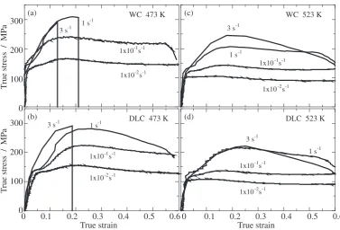
The stress-strain curves of AZ31 magnesium alloy at 473 and 523 K are shown in Fig. 1. The deformation stress for the sample by WC was slightly higher than that for the sample by DLC at 473 K. These results show that the DLC tool effectively lower the stress in comparison with the WC tool at 473 K. At 473 K, the samples by DLC deformed without cracks up to a strain rate of 1 s1, while the samples by WC up to 101s1. In contrast, at 523 K, the specimens were deformed without cracking whether the DLC tool or the WC tool was used at all the strain rates examined. There were few 0
100 200
300 WC 473 K
3 s-1
1x10⁻¹s-1
1x10⁻²s-1 1 s-1
T
rue stress / MP
a
(a) WC 523 K
1 s-1 3 s-1
1x10⁻¹s-1
1x10⁻²s-1 (c)
0 0.1 0.2 0.3 0.4 0.5 0.6
0 100 200
300 3 s-1 DLC 473 K
1x10⁻¹s-1
1x10⁻²s-1 1 s-1
T
rue stress / MP
a
True strain
(b)
0 0.1 0.2 0.3 0.4 0.5 0.6
DLC 523 K
1 s-1 3 s-1
1x10⁻¹s-1
1x10⁻²s-1
True strain
(d)
Fig. 1 True stress and true strain curves of the samples: (a) by WC at 473 K, (b) by DLC at 473 K, (c) by WC at 523 K and (d) by DLC at
[image:2.595.107.485.68.324.2]differences in stress level at 523 K between the specimen by WC and DLC.
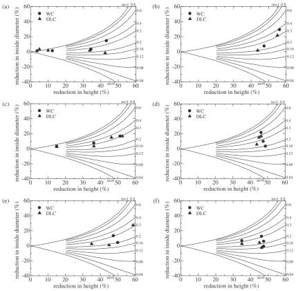
The comparison between the measured data and the calibration curves for friction coefficient is shown in Fig. 2. In the plot, the data for the specimens with cracks were removed. The measured data for the samples by WC and DLC were approximately fitted on the curves, respectively. Measured friction coefficients are shown in Table 1. At 473 K, the friction coefficient for the sample by WC is higher
than that for the sample by DLC at each strain rate. These results show that the DLC tool keeps the friction lower than the WC tool at 473 K. In contrast, at 523 K, there were no differences of friction coefficient between the samples by DLC and WC. It is considered that the difference of friction coefficient between WC and DLC is small due to instability of the interface between the tool and the specimen at 523 K. Chiang et al.8) have indicated that the deformation
mechanisms of the magnesium alloy influences to the dynamic friction coefficient at elevated temperatures, and magnesium alloys possibly change the deformation mecha-nisms during high temperature deformation due to the dynamic recrystallization (DRX). Therefore, the estimation of the deformation mechanisms all the while testing should be required.
In general, the constitutive equation for deformation at elevated temperature is expressed as:11)
_
"
"¼A Gb kT b d p th G n
D ð3Þ
0 10 20 30 40 50 60
-40 -20 0 20 40 60 WC DLC m=0 0.04 0.08 0.12 0.16 0.2 0.3 0.4 0.6 0.8 m=1
reduction in inside diameter (%)
reduction in height (%)
0 10 20 30 40 50 60
-40 -20 0 20 40 60 WC DLC m=0 0.04 0.08 0.12 0.16 0.2 0.3 0.4 0.6 0.8 m=1
reduction in inside diameter (%) -400 10 20 30 40 50 60
-20 0 20 40 60 WC DLC m=0 0.04 0.08 0.12 0.16 0.2 0.3 0.4 0.6 0.8 m=1
reduction in inside diameter (%)
reduction in height (%)
0 10 20 30 40 50 60
-40 -20 0 20 40 60 WC DLC m=0 0.04 0.08 0.12 0.16 0.2 0.3 0.4 0.6 0.8 m=1
reduction in inside diameter (%)
reduction in height (%) reduction in height (%)
0 10 20 30 40 50 60
-40 -20 0 20 40 60 WC DLC m=0 0.04 0.08 0.12 0.16 0.2 0.3 0.4 0.6 0.8 m=1
reduction in inside diameter (%)
reduction in height (%)
0 10 20 30 40 50 60
-40 -20 0 20 40 60 WC DLC m=0 0.04 0.08 0.12 0.16 0.2 0.3 0.4 0.6 0.8 m=1
reduction in inside diameter (%)
reduction in height (%)
(a) (b)
(c) (d)
(e) (f)
Fig. 2 Calibration curves including experimental results: (a) at 473 K and1:0102s1, (b) at 473 K and1:0101s1, (c) at 523 K
[image:3.595.83.512.70.491.2]and1:0102s1, (d) at 523 K and1:0101s1, (e) at 523 K and 1 s1, and (f) at 523 K and 3 s1.
Table 1 Friction coefficient measured by the calibration curves in Fig. 2 of
the sample by WC and DLC at 473 and 523 K and at strain rates of102,
101, 1 and 3 s1.
Strain rate 102s1 101s1 1 s1 3 s1
473 K WC 0.30 0.35 — —
DLC 0.20 0.25 0.20 —
523 K WC 0.30 0.35 0.25 0.25
[image:3.595.46.292.584.655.2]where ""_ is the strain rate, A is a constant, G is the shear modulus {¼E=ð2 ð1þÞÞ, E is the Young’s modulus [¼4:3104 ð15:3104 ðT300ÞÞ],
is Poisson’s ratio andT is the absolute temperature},bis the Burgers vector,kis the Boltzmann’s constant,dis the grain size,pis the grain size exponent,is the flow stress,this the
threshold stress,nis the stress exponent andDis the diffusion coefficient {¼DoexpðQ=RTÞ: Do is the pre-exponential
factor for diffusion,Ris the gas constant,Qis the activation energy}. There are three deformation modes for the possible mechanisms in the strain rate range for plastic forming in magnesium alloys: (a) slip accommodated grain boundary sliding process, which is accepted as the dominant deforma-tion mechanism for superplastic flow,12–14) (b) glide
con-trolled dislocation creep15)and (c) climb controlled
disloca-tion creep.16)The constitutive equations for each deformation
are expressed as:
_
"
"¼1:8106 Gb
kT b d 2 th G 2
DLþ1:7102
d Dgb
ð4aÞ
_
"
"¼3:0102 Gb
kT
th
G
3
Ds ð4bÞ
_
"
"¼3:61011
Gb 3 Gb kT G 5
DLþ3
G
2
Dp
ð4cÞ
where DL is the diffusion coefficient for the lattice
(¼1:0104expð135000=RTÞ), is the grain boundary
width (taken to be 2b in the present analysis), Dgb is the
diffusion coefficient for the grain boundary (¼5:0
1012expð92000=RTÞ) D
s is the diffusion coefficient for
the solute atom (¼1:2103expð143000=RTÞ), is the
stacking fault energy (27.8 mJ/m2 for Mg-3 mass%Al), and
Dp is the pipe diffusion content.
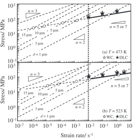
The relationship between the flow stress and the strain rate for magnesium alloys at 473 and 523 K is shown in Fig. 3, where the diffusion coefficient and shear modulus of AZ31 magnesium alloy were taken to be those of pure magnesium. Due to independence for each mechanism, the fastest mechanism appears deformation behavior for the materials. The transition points of the deformation mechanisms are superimposed as the open circle. It is noted that grain size less than 2mmis required to behave superplastic deformation at 473 K and in a strain rate range of 102 to 3 s1 for AZ31
magnesium alloy. It is also noted that grain size less than 3mm is required to behave superplastic deformation at 523 K and in a strain rate range of 102 to 3 s1 for AZ31
[image:4.595.314.538.68.301.2]magnesium alloy.
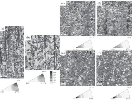
Figure 4 shows the EBSD maps and the inverse pole figures of the specimens before and after deformation from the direction of the compressive axis: (a) as extruded AZ31 alloy, (b) pre-heated alloy at 473 k for 10 min, (c) deformed at
102s1 by WC tool and (d) by DLC tool, (e) deformed at 1 s1 by WC tool and (f) by DLC tool. In the figure, misorientation angle more than 15 is represented as solid line, which is defined as grain boundaries, and that between 2
to 15 is represented as dotted line, respectively. In as extruded AZ31 alloy, the average grain size is 15mmand the deformation mechanism at the present testing conditions is corresponded to a region characterized by the climb-controlled dislocation creep (Fig. 3). It is found that both the samples after testing have the fine grain size little less than the initial grain size at 15mm, namely, DRX caused during the compressive flow. The grain was refined in the deformation at any testing conditions, and the grain size decreases with increasing strain rate and decreasing testing temperature. Average grain sizes after deformation were 3.3– 9.1mmin the present testing conditions. These values are in good agreement with the estimated values from the pervious report.17)
The date of the flow stress and the strain rate in this testing condition are plotted in Fig. 3. The open stars are the date for the sample by WC and the close stars are that by DLC, respectively. It is noted that the AZ31 magnesium alloy unalterably indicates the climb controlled dislocation creep during compressive testing in the present testing conditions, although the grain refinement has occurred by DRX. Then, the deformation mechanism did not affect the dynamic friction properties in the present testing conditions.
In Fig. 4, it is also noted that the (10-10) plane is perpendicular to the extruded direction and the compressive axis in the deformed specimens. The basal plane aligned to the plane perpendicular to the compressive direction during the compressive tests. We have found that the crystal orientation dependence of the sample by DLC tool was smaller than that of the sample by WC tool and the difference
10-7 n = 3
(a) T = 473 K
WC, DLC n = 2
n = 5 or 7
10-1 100 101 102 103
10-6 10-5 10-4 10-3 10-2 10-1 100 101
Strain rate/ s-1
Stress/ MP
a
(b) T = 523 K
WC, DLC n = 2
10-1 100 101 102 103 Stress/ MP a
d = 1 µm 3 µm
5 µm 15 µm 10 µm
d = 1 µm 3 µm
5 µm 15 µm 10 µm
n = 3
n = 5 or 7
Fig. 3 The relationship between flow stress and strain rate for slip
accommodated grain boundary sliding process (n¼2), glide-controlled
dislocation creep (n¼3), and climb controlled dislocation creep (n¼5or
7) at 473 K and 523 K, where the open circles indicate the transition point of deformation mechanism for various grain sizes, the open and the close star marks indicate the flow stress and the strain rate of the samples by WC tool and DLC tool in this test condition. The dash line perpendicular to
x-axis indicates 1:0102s1. Indicated heavy solid line is the testing
[image:4.595.92.276.277.424.2]of friction coefficient affected the texture after deformation at 473 K and at a strain rate of102s1in the previous paper.9)
In order to evaluate the change in the texture quantitatively in the wide testing conditions, the ratio of the grains within 10 degree from h0001i direction to compressive axis was measured. Table 2 shows the result. At 473 K, the ratio of the grains within 10 degree from h0001i direction to compressive axis for the sample by WC was larger than that for the sample by DLC, which is in good agreement with the change in friction coefficient as shown in Table 1. This result indicates that higher friction coefficient in the sample by WC would cause the increase in the compressive stress compo-nent by the higher interactive restraining-force (or binding-force) between the interfaces of the materials and the tools, resulting in the development of basal texture.
4. Conclusion
We obtained the following conclusions about dynamic friction properties for AZ31 magnesium alloy during defor-mation.
The grain size was refined from an initial grain size of 15mmto the dynamically recrystallized grain size of less than 5mmin both the samples deformed by WC and DLC tools. From the judgment of the grain size dependency on deformation mechanisms, the dominant deformation mech-anism of the current magnesium alloy under the present testing conditions was the climb controlled dislocation creep. At 523 K, the friction coefficient was not changed very much between WC tool and DLC tool. At 473 K, the friction coefficient for the sample deformed by DLC tool was smaller than that deformed by WC tool. DLC tool enables lower friction coefficient than WC tool. In addition, the difference of the microstructure by tools especially appeared to the texture. The intensity of the basal plane within 10 degree fromh0001ifor the sample by DLC is lower than that for the sample by WC at 473 K. The correlation was admitted in friction coefficient and the intensity of the basal plane.
Acknowledgements
This work was partly supported by the Chian Hsing (a)
(b)
(c) (d)
(e) (f)
Fig. 4 The EBSD maps and inverse pole figures of the samples of (a) as extruded AZ31 alloy, (b) pre-heated alloy at 473 k for 10 min,
(c) deformed at102s1by WC tool and (d) by DLC tool, (e) deformed at 1 s1by WC tool and (f) by DLC tool. The analysis direction is
[image:5.595.72.525.71.414.2]parallel to the compressive axis.
Table 2 The ratio of the grains within 10 degree fromh0001idirection to
compressive axis of the sample by WC and DLC at 473 and 523 K and at
strain rates of102,101, 1 and 3 s1.
Strain rate (s1) 1102 1101 1100 3100
473 K WC 13.2 21.3 — —
DLC 5.6 9.9 27.0 —
523 K WC 0.4 9.5 9.7 7.6
[image:5.595.46.291.513.583.2]Forging Industrial Co., LTD (Taichung). The authors thank Kasatani Corp. for supplying lubricant.
REFERENCES
1) H. Okahara, M. Ohara, Y. Takigawa and K. Higashi: Mater. Trans.47
(2006) 954–958.
2) N. Koga and R. Paisarn: J. Jpn. Soc. Technol. Plast.42(2001) 145–149.
3) A. Takara, Li-Fu Chian, S. W. Chung, H. Somekawa, H. Watanabe, Y.
Takigawa and K. Higashi: Mater. Trans.49(2008) 898–902.
4) T. Male and M. G. Cockcroft: J. Inst. Metals93(1964–65) 489–494.
5) T. Roghu, O. Sivakesavam and G. G. Saha: J. Master. Process. Technol.
42(1994) 349–360.
6) R. Matsumoto and K. Osakada: CIRP Annals Manufact. Technol.51
(1), (2002) 223–226.
7) K. Chen, T. B. Huang and S. G. Chen: Int. J. Adv. Manuf. Technol.32
(2007) 272–279.
8) L. F. Chiang, H. Hosokawa, J. Y. Wang, T. Uesugi, Y. Takigawa and K.
Higashi: Mater. Trans.51(2010) 1249–1254.
9) L. F. Chiang, N. Nishioka, J. Y. Wang, H. Hosokawa, T. Uesugi, Y.
Takigawa and K. Higashi: Mater. Trans.51(2010) 477–481.
10) A. T. Male and M. G. Cockcroft: J. Inst. Metals93(1964–1965) 38–46.
11) H. J. Frost and M. F. Ashby: Deformation-mechanism Maps, (Pergamon Press, 1982) pp. 44–45.
12) H. Watanabe, T. Mukai, M. Kohzu, S. Tanabe and K. Higashi: Acta
Mater.47(1999) 3753–3758.
13) H. Watanabe, T. Mukai, M. Ishikawa, M. Mabuchi and K. Higashi:
Mater. Sci. Eng. A307(2001) 119–128.
14) H. Watanabe, T. Mukai, M. Mabuchi and K. Higashi: Acta Mater.49
(2001) 2027–2037.
15) H. Watanabe, H. Hosokawa, T. Mukai and T. Aizawa: Materia Japan
39(2000) 347–354.
16) H. Somekawa, K. Hirai, H. Watanabe, Y. Takigawa and K. Higashi:
Mater. Sci. Eng. A407(2005) 53–61.
17) Y. Takigawa, M. Honda, T. Uesugi and K. Higashi: Mater. Trans.49