© 2019, IRJET | Impact Factor value: 7.211 | ISO 9001:2008 Certified Journal | Page 6404
Frequency Control of Distributed Generators in Microgrid with
ANFIS Controller
K. Hema
1, P. Maruthupandi
21
M.E II year, Department of EEE, Government College Technology, Coimbatore, India
2
Assistant Professor, Department of EEE, Government College Technology, Coimbatore, India
---***---Abstract -
Frequency deviation is the major problem inmicrogrid due to the varying power output from the renewable energy sources. In this paper, solar and wind are taken as prime source of power. Since the renewables lack inertia diesel-generator is used to provide inertia to the system and energy storage devices are used. The proposed controller has less settling time compared to the conventional controllers. Artificial neuro-fuzzy inference system (ANFIS) controller combines the features of fuzzy and neural and has improved performance where the fuzzy rules modify the network according to the power output. The results are obtained using MATLAB/Simulink model.
Key Words: renewables, frequency deviation, settling
time, fuzzy, ANFIS.
1. INTRODUCTION
A hybrid energy system might consist of various renewable energy conversion component like wind turbine, PV array and hydro turbines as well as conventional non-renewable generators like diesel generators, and storage devices. To overcome the incredible power crisis in the country, the best way is to make use of renewable energy sources. It is inexhaustible and non-polluting. It has the advantages of low running and maintenance cost and also noiseless operation.
The voltage power characteristic of a photovoltaic (PV) array is nonlinear and time varying because of the changes caused by the atmospheric conditions [1]. When the solar radiation and temperature varies, the output power of the PV module is also getting changed. But to get the maximum efficiency of the PV module it must be operated at maximum point,so it is necessary to operate the PV module at its maximum power point for all irradiance and temperature conditions[2]. To obtain maximum power from photovoltaic array, photovoltaic power system usually requires maximum power point tracking controller (MPPT).
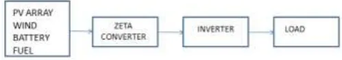
Block diagram of the microgrid is shown in fig.1. Here Solar, wind, diesel are used as prime source of power production and energy storage devices such as battery and fuel cell are used. The power produced from PV array is varying according to irradiance and temperature hence a zeta converter is used to boost the voltage level. Inverter is
used before connecting to the load. Similarly wind, battery and fuel cell are simulated in the same fashion as earlier.
Fig -1: Block diagram of test system
Paper is as follows. In introduction an overview is given. Solar panel is simulated along with converter and inverter. Wind energy conversion system is modelled followed by diesel engine generator and energy storage units such as battery and fuel energy storage systems. Initially PI controller is used to attain stability and the proposed controller is implemented which shows improved performance which are discussed in the results section.
2. MODELLING COMPONENTS
2.1. PV ARRAY
Photovoltaic cells are connected electrically in series and/or parallel circuits to produce higher voltages, currents and power levels. Photovoltaic modules consist of PV cell circuits sealed in an environmentally protective laminate, and are the fundamental building blocks of PV systems. Photovoltaic panels include one or more PV modules assembled as a pre-wired, field-installable unit. A photovoltaic array is the complete power-generating unit, consisting of any number of PV modules and panels.
[image:1.595.322.572.254.298.2]© 2019, IRJET | Impact Factor value: 7.211 | ISO 9001:2008 Certified Journal | Page 6405
Fig -2: Simulink diagram of solar systemAs the amount of sunlight varies, the load characteristic that gives the highest power transfer efficiency changes, so that the efficiency of the system is optimized when the load characteristic changes to keep the power transfer at highest efficiency. This load characteristic is called the maximum power point (MPP) and MPPT is the process of finding this point and keeping the load characteristic there. Electrical circuits can be designed to present arbitrary loads to the photovoltaic cells and then convert the voltage, current, or frequency to suit other devices or systems, and MPPT solves the problem of choosing the best load to be presented to the cells in order to get the most usable power out.
Fig -3:Schematic diagram of Zeta converter
Zeta, or ‘inverse sepic’, is a dc-dc converters, like Cuk and Sepic, that have a capacitor in series with the power path. Both zeta and Sepic have the same transfer function,
Vout=Vin x D/(1-D) ---(1)
Zeta has many advantages, such as input to output DC insulation, buck-boost capability and continuous output current, but it is difficult to control, according to Microchip in its AN1467.
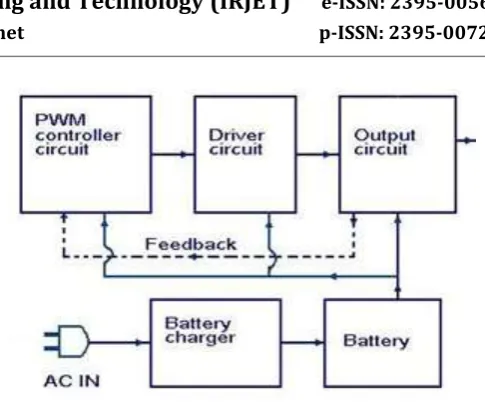
Fig -4: Block diagram of PWM inverter
Pulse Width Modulation or PWM technology is used in Inverters to give a steady output voltage of 230 or 110 V AC irrespective of the load. The Inverters based on the PWM technology are more superior to the conventional inverters. The use of MOSFETs in the output stage and the PWM technology makes these inverters ideal for all types of loads. In addition to the pulse width modulation, the PWM Inverters have additional circuits for protection and voltage control. The quality of the output wave form from the inverter determines its efficiency. The quality of the inverter output wave form is expressed using Fourier analysis data to calculate the Total Harmonic Distortion (THD). THD is the square root of the sum of the squares of the harmonic voltage divided by the fundamental voltage.
THD = √ V2 2 + V3 2 + V4 2…………. Vn 2 / V1 ---(2)
Based on the output waveforms, there are three types of Inverters. These are Sine wave, Modified Sine wave or Quasi sine wave and Square wave inverters.
2.2.
WIND ENERGY CONVERSION SYSTEM
Fig -5:Simulink diagram of wind system
[image:2.595.313.556.55.256.2] [image:2.595.48.291.120.258.2] [image:2.595.36.289.456.562.2] [image:2.595.337.559.558.691.2]© 2019, IRJET | Impact Factor value: 7.211 | ISO 9001:2008 Certified Journal | Page 6406
control exploits the injected power to provide anappropriate frequency response using pitch angle controller as shown in fig.5
2.3 Diesel engine generator
Fig-6: Simulink diagram of diesel engine generator
A diesel generator is the blend of a diesel motor with an electric generator (regularly an alternator) to produce electrical energy. This is a particular instance of motor generator. A diesel pressure start motor frequently is intended to keep running on fuel oil, yet a few sorts are adjusted for other liquid fuels or natural gas. Diesel generating sets are utilized as a part of spots without connection with a power grid, or as emergency powersupply if the grid fails, and also for more complex applications, for example, peak-lopping, grid support and fare to the power grid.
2.4 Battery energy storage system
Fig-7: Simulink diagram of battery energy storage system.
Battery system comprises of cells which have a qualities working voltage and most extreme current potential. Dominant part of battery energy storages system have
control power system that handle electricity from the battery and makes it suitable for AC loads. This including changing the current and voltages to maximize the power output, coordinating the changed over AC power to AC electrical system and goes to the end current flow out of the system into grid during outages. The change from DC to AC power in power conditioning system is finished by an inverter.
2.5 Fuel energy storage system
Fig-8:Simulink diagram of fuel energy storage system
Hydrogen fuel cell (HFC) fascinates academics and industrialists because it is suitable for emission-free electricity generation and can be applicable in distributed generation to the automobile industry. When burned, HFC releases water vapor only into the environment. HFC burns faster and contains considerable chemical energy per mass (142 MJ) compared with other hydrocarbon fuels. HFC has high energy density by weight and low energy density by volume. The environmental impact of hydrogen storage is desirable, which leads governments across the globe to enhance the prospects of the hydrogen economy.
3. Proposed Controller
© 2019, IRJET | Impact Factor value: 7.211 | ISO 9001:2008 Certified Journal | Page 6407
are adaptive parameters of the layer and are calledconsequent parameters.
(a)
(b)
(c)
Fig-9: Membership function of Fuzzy controller, (a)&(b) represents the input function and (c) represents output
function
4
.
Simulation and Results
The simulink models which are modeled separately are given to load through a common bus as shown in fig.10. The frequency is measured at the loading unit by PLL. The frequency deviation and the derivative of frequency deviation are given as the input to the fuzzy and the error signal is given as the input to the neural network. The fuzzy rules are designed as shown in fig.9.
Fig-10: Simulink diagram of standalone microgrid
Fig-11: Architecture of ANFIS
Fig-12: Frequency plot of PI controller without DG
© 2019, IRJET | Impact Factor value: 7.211 | ISO 9001:2008 Certified Journal | Page 6408
Fig-14: Frequency plot using ANFIS controller5. Conclusion
The results are obtained using MATLAB/Simulation. Initially only the sources are connected without any external inertia .PI controller has higher settling time (0.3S) as shown in fig12. Then diesel engine generator is added to the system and shows settling time comparatively less (0.1S).Finally the proposed ANFIS controller is used and frequency stability is achieved at 0.08S and it is superior to other controllers as shown in fig14.The work undertaken is for standalone microgrid and futher it may be modified as an islanded microgrid or grid connected microgrid.
REFERENCES
[1] Ansari, S. Chaterjee, and A. Iqbal, “Fuzzy logic
control scheme for solar photo voltaic system for maximum power point tracker,” Int. J Sustain. Energy, vol. 29, no. 4, pp. 245–255, Apr. 2010.
[2] E. Kremers, P. Viejo, O. Barambones and J. G. d.
Durana, "A Complex Systems Modelling Approach for Decentralised Simulation of Electrical Microgrids," 2010 15th IEEE International Conference on Engineering of Complex Computer
Systems, Oxford, 2010, pp. 302-311.
[3] Bevrani, H., Daneshmand, P.R.: ‘Fuzzy logic-based
load frequency control concerning high penetration of wind turbine’, IEEE Syst. J., 2012, 6, (1), pp.173–180.
[4] Cam, E.: ‘Application of fuzzy logic for load
frequency control of hydro electrical power plants’, Energy Convers. Manage., 2007, 48, pp. 1281–1288.
[5] T. L. Kottas, Y. S. Boutalis, and A. D. Karlis, “New
maximum power tracker for PV arrays using fuzzy controller in close cooperation with fuzzy cognitive networks,” IEEE Trans. Energy Convers., vol. 21.
[6] Hassan Bevrani, Fuzzy Logic-Based
Load-Frequency Control Concerning High Penetration
of Wind Turbines, IEEE SYSTEMS JOURNAL, Vol. 6, no. 1, March 2012.
[7] A.A. Salarn, A. Moharned, and M. A. Hannan, "
Technical challenges on Microgrids,"Asian Research Publishing Network (ARPN), vol. 3, no. 6, pp. 64-69, Dec. 2008.
[8] M. S. Mahmoud, M. Saif Ur Rahman and F. M. A. L.
-Sunni, "Review of microgrid architectures – a system of systems perspective," in IET Renewable
Power Generation, vol. 9, no. 8, pp. 1064-1078, 11
2015.
[9] Ngamroo I, “Robust frequency control of wind–
diesel hybrid power system using superconducting magnetic energy storage”. Int J Emerg Electr Power Syst 2009;10(2).
[10]I.Serban and C. Marinescu, “Aggregate
load-frequency control of a wind-hydro autonomous microgrid,” Renew. Energy, vol. 36, no. 12, pp. 3345–3354, 2011.
[11]H. Bevrani, “Robust load frequency controller in a