© 2019, IRJET | Impact Factor value: 7.211 | ISO 9001:2008 Certified Journal | Page 2346
Hob Grinding Machine Automation using PLC&HMI
Ms. Lavanya D C
1, Mrs. Shakunthala C
2¹M. Tech CAID, Dept. of Electrical & Electronics Engineering, The National Institute of Engineering, Mysuru, Karnataka, India
²Assistant Professor, Dept. of Electrical & Electronics Engineering, The National Institute of Engineering, Mysuru, Karnataka, India.
---***---ABSTRACT:-The Hob Grinder is a vital part in any engineering works. Usually in order to smoothen or flatten any surface we generally prefer grinding process, the grinding process can be done in surface area or metal portion in any possible areas or metal portion in any possible area we want. The grinding process is the most popular finishing process because of its high accuracy, efficiency, and flexibility in work piece modification. After the inspection of the Grinder machine, it was found that machine operating in manual mode has very low grade quality production and less accurate. Using PLC and HMI, the Hob Grinder machine can be automated to reduce manual work with more accurate tuning to increase productivity. The proposed work has taken up, fabrication of an automated Hob Grinder Machine based on PLC and HMI for the design and implementation. The objective of the project is automated control of Hob Grinder machines to produce a finished Product.
Key words:-PLC(Programmable logic control), HMI(Human machine interface)
I. INTRODUCTION
Human requirements are increasing day by day whereas factories are running out of resources. Most of the mechanical industries produce products in bulk. The main idea of mass production is to meet the requirement of the consumer, to maintain consistent quality & make each product cost effective. To meet these demands industries need to enhance the quality and quantity of their production.
Advancements in technology results in revolution of manufacturing industries for increased productivity. Key goal of manufacturing industries is to automate for high performance machining. Automated equipment and good shop layout
normally improves speed, precision and quality regardless of which type of machinery is performed. many industries use PLCs in automation process to diminish production cost and to increase quality and reliability. Earlier digital controllers and PID Controllers are used for speed control of drives. PC+PLC based control systems are widely spreading, not only in the discrete and sequence control processes but also in continuous control processes, because of rapid improvement in performance of PC and PLC, development and introducing of effective PLC-instrumentation control units.
Programmable logic controller(PLCs) have been deployed for many decades for standard control in industrial and factory environmental. PLCs have become efficient and provides robust platform with applications beyond the standard control and industrial automation. Human machine interface (HMI) formerly known as man-machine interface, are usually availed to communicate with PLCs and other computers, such as monitoring temperatures and pressures for further Automated control.
The Hob Grinder machine monitored and is controlled by PLC and HMI unit, the Control scheme of Hob Grinder machine is the inter-connection and information exchange between PLC, HMI, inputs and outputs devices. The designation stage includes software demands, hardware choice, panel wiring and automation for the machine.
© 2019, IRJET | Impact Factor value: 7.211 | ISO 9001:2008 Certified Journal | Page 2347 A. EXISTING SYSTEM
In existing system the Hob Grinding machine is operated based on Relay Logic Control system. Disadvantages of relay logic control system:
Not flexible for larger system.
Using relay system lead to problems like having more number of wirings. Relay system takes more breakdown time.
Costlier frequent maintenance.
Human intervention cannot be avoided. Increases electrical noise and interference. If any fault occurs its difficulty to identify that
problem. II.METHODOLAGY
PLCs implement the control functions using integrated circuits instead of electromechanical devices. They are capable of storing instructions, like arithmetic, counting, data manipulation, sequencing, timing, and communication, to control the machine and process sequence. This reduces machine downtime and provides expandability for the future applications. The process involves different sensors and actuators for proper functioning of the machine described as below. Proximity sensors are placed at core and vertical motor to detect the position of cylinders. This controls the opening and closing time and speed of the cylinders.
Based on the signals obtained from input devices (sensors), actuation of motors and solenoids are carried out as per the requirement. This project is aimed to design application software which collects the input data from the proximity sensors and executes, or performs, the control program stored in the PLC memory and updates the output devices such as hydraulic motor, solenoids, motor starters etc. B. PROPOSED SYSTEM
The proposed system involves replaced with PLC which combines each individual systems into a single system for controlling, monitoring and data logging as shown in Fig.1.1 It is easier to troubleshoot the problem with the use of alarms and diagnostics data on HMI. This provides safer and remote operation for user. Breakdown time of the system is
[image:2.612.338.558.206.439.2]limited to 30-60 minutes which results in increase in productivity and considerably minimizes the maintenance cost. Setup time is also minimized & needless to change log sheet every day, since data can be taken anytime in pen drive up to one week. To provide better solutions for critical applications the accuracy of the system is greatly improved down to or below 0.03%.
fig. 1.1 Hob grinding machine set in to automation
PLC HMI PUSH BUTTON
AND SELECTOR SWITCH
INDICATOR
MOTOR SENSORS
SOLENOIDS
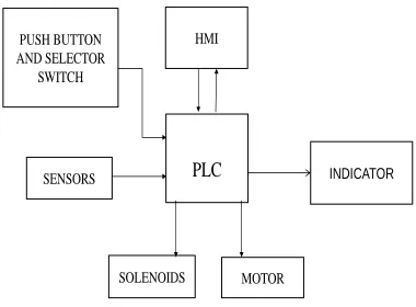
[image:2.612.355.545.489.629.2]© 2019, IRJET | Impact Factor value: 7.211 | ISO 9001:2008 Certified Journal | Page 2348 Fig 1.2 shows a block diagram for automation of hob
grinding using PLC and HMI. The basic components of Hob grinding are
PLC- Programmable Logic Controller. HMI- Human machine interface
For forward and backward movement motor Grinding wheel induction motor
Induction motor on job head for the continuous rotation of work piece.
Hydraulic motor. Dust collector motor.
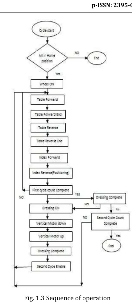
B.OPERATIONAL SEQUENCE
Fig 1.3 shows the sequence of operation for the operation for the Hob Grinding machine.
Start the motor using MPCB and push button. Manually set the first cycle teeth count, second cycle teeth count, Index forward count and index dwell.
Initially all motors are will be in home position, Using sensors PLC check the all motors and spindles are in home position if yes the wheel starts to rotate , if not then wheel does not start to rotate.
Now wheel ON condition, With help of Hydraulic motor the spindle move forward end to reverse end.
[image:3.612.341.555.63.555.2] After index take position , with the help of hob blade work piece will be cut and sharpening required first cycle teeth count, if not complete the first cycle then repeat the initial condition.
Fig. 1.3 Sequence of operation
After completion of first cycle dressing mode on. Now vertical motor move towards downward. The dust collector motor collect the dust and small unwanted metal pieces, then vertical motor move to up then finish the dressing.
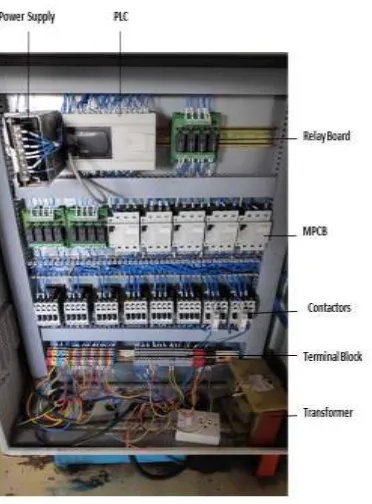
© 2019, IRJET | Impact Factor value: 7.211 | ISO 9001:2008 Certified Journal | Page 2349 III. DESIGN OF CONTROL PANEL
Fig 1.4. control panel
Control panel is a cabinet that contains electrical elements to regulate the motor and equipment. They're found in factories to watch and control machines or production lines and in places like ships, aircraft, atomic energy plants, and mainframe computers. Earlier control panels are most often equipped with analog instruments and push buttons, whereas nowadays in many cases touch screens are used for monitoring and control purposes. Control panel being manufactured for the Hob Grinding machine mainly consists of Programmable Logic Controller (PLC), Human Machine Interface (HMI), relay boards, etc. These components are wired and connected to the Hob grinding machine.
A. SPECIFICATION OF THE CONTROL PANEL COMPONENTS
Components that are to be fixed in to control panel to automate Bladder Curing Press machine is as shown in the table below
# Qt y
Item
1 1 600x800x250 Panel Board
2 1 SMPS
3 1 MCB
4 1 4P 25A Rotary Switch
5 1 4-6A, MPCB
6 2 3.2-5A, MPCB
7 2 2.5-4A, MPCB
8 8 38A, Contactor
9 3 Relay Logic Board
10 1 4" Exhaust Fan
11 2 4" Dust Cover
12 1 WTBD
13 1 HMI
14 1 PLC, FX5U, 40I/40O,64K program capacity
Table 1: Control panel components
IV. RESULTS AND DISCUSSION
A.IMPLEMENTATION RESULTS
[image:4.612.74.260.117.369.2]© 2019, IRJET | Impact Factor value: 7.211 | ISO 9001:2008 Certified Journal | Page 2350 Fig. 1.5(a) Initialization of the program
As per the methodology explained earlier Hob grinding machine is automated using PLC & HMI. Fig 5.1 (a) shows the online execution of initialization part of the program. The Fig: 5.1(b) below show hob grinding machine automated using PLC&HMI. Fig 5.1 (a) shows the entire working of the Hob grinder is controlled. We used both hardware and software package techniques in controlling the entire operation of the machine. During manual operation of Hob grinder, workers, working on the machines face difficulty in synchronizing the speed between grinding wheel and the job head. Both are continuously rotating at some speed. There is also a problem in the movement of slide which brings the grinding wheel near to the work piece for appropriate cutting of the extra material from the work piece. So in order to overcome all these difficulties, we use PLC GX Developer. It gives command to various drives and limit switches. In other words it controls entire working of the machine. The various dimension of the work piece i.e. number of cycles, number of teeth etc. are entered through GT Designer (HMI).
If we wish to control the machine manually, we can select that mode through HMI. This HMI is connected to PLC and PLC programming is done in LD language using software.
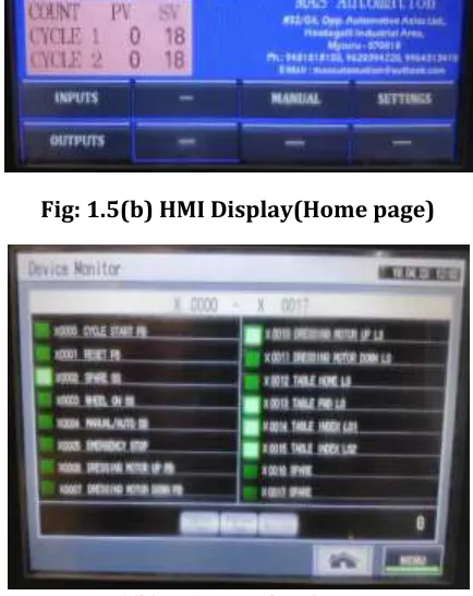
B. DEVELOPED HMI DISPLAY
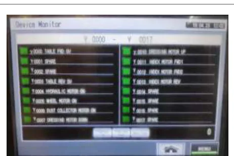
On selecting I/O list on HMI screen 1, the HMI screens of input and output being given to PLC is also visible which helps the user to track the program.
Fig: 1.5(b) HMI Display(Home page)
Fig1.5(b) HMI Display for inputs
[image:5.612.47.271.55.266.2] [image:5.612.341.558.234.507.2]© 2019, IRJET | Impact Factor value: 7.211 | ISO 9001:2008 Certified Journal | Page 2351 Fig. 1.5(c) HMI Display for Outputs
Fig 1.5(c) shows the HMI display for outputs. The icon named MAIN leads the screen from present page to home page when clicked; similarly the NEXT icon goes to the next page. PREV icon goes to the previous page.
V.CONCLUSION AND FUTURE WORK
A. CONCLUSION
Hob grinding machine with obsolete PLC was time consuming and requires maintenance. Thus Automation of the machine with latest PLC has enhanced the performance of the machine, by increasing the productivity and accuracy. HMI enables non-skilled labors also for easy operation of machine. Also with the inclusion of hob grinding machine operation requires less labor power with good quality of product. This will fulfill all the requirements of the industry with good levels of accuracy and repeatability thereby yielding a more robust system.
B. FUTURE WORK
Though the automation of the machine was found to be successful, energy saving can be enhanced by adding variable frequency drives(VFD) for hob grinding machine
REFERENCE
[1] Pei Ruilin n Fang Ying, “Variable Structure Speed Regulation of induction motor in Steel Manufactures”, IEEE international Conference, Vol. 1, pp.710-714, 2005.
[2] Wilson, J.E.; Bried, F.; “Application of programmable logic controllers for pipeline local and remote control", IEEE Transactions, Vol. 24, Issue 6, pp.1082-1088, 1988.
[3] QiaoDongkai; Yang Xiang-yu; Jia Jinxin “The Application of PLC in grinding mechanism” Second International Conference on Digi-tal Manufacturing and Automation (ICDMA), pp.1213-1216, 2011.
[4] Ronald Schoop, Ralf Neubert, Boris Suessmann, “Flexible grinding Control with PLC, and Software Agents”, Proceedings of 5th Inter-national Symposium on Autonomous Decentralised system, 2001, pp. 365-371.
[5] Shivanagoud Biradar, S Puneeth, “Automationof Tube Cutting Machine Using PLC and HMI”, International Journal of Advances in science and technology, Volume 15, Issue July 2017 ISSN 5216. [6] Masao Ogawa and Yutaka Henmi,” Recent Developments on PC+PLC based Control Systems for Beer Brewery Process Automation Applications” SICE-ICASE International Joint Conference 2006 Oct. 18-21, 2006 in Bexco, Busan.
[image:6.612.47.278.79.233.2]