IP-Layer Soft Handoff Implementation in ILNP
Ditchaphong Phoomikiattisak
School of Computer Science University of St Andrews, UK[email protected]
Saleem N. Bhatti
School of Computer Science University of St Andrews, UK[email protected]
ABSTRACT
We present the first results of an implementation of IP-layer soft handoff, based on the Identifier Locator Network Pro-tocol (ILNP). In our testbed experiments, we show minimal gratuitous packet loss in vertical handoff scenarios (WiFi-3G). Unlike the IETF Mobile IP proposals, the ILNP uses a purely end-to-end architecture, and does not require proxies, middleboxes or tunnelling to support mobility. Our testbed is based on an in-kernel implementation using a modified Linux IP stack.
Categories and Subject Descriptors
C.2.1 [Computer-Communication Networks]: Network
Architecture and Design—Wireless communication; C.2.2 [Computer-Communication Networks]: Network Pro-tocols
Keywords
Mobility Management; Vertical Handoff; Identifier-Locator Separation; Linux Kernel
1.
INTRODUCTION
Seamless mobility is increasingly desired today. Lower level network technologies, such as 3G/4G networks or wire-less LAN (WLAN or WiFi) networks already enable mobil-ity support, by allowing mobilmobil-ity within the same underlying technology,horizontal handoff. However, effective solutions to enable seamlessvertical handoffacross different wireless technologies are still developing. In this paper, the term
handoffalways means avertical handoff.
The problem of mobility in an IP network can be described with the help of Table 1. As shown in the second column, an IP address is used to bind state in the transport layer, but is assigned to a specific physical interface – it acts as
anidentifier at the transport and physical layer. However,
the IP address is also used at the network layer for routing – it acts as a locator. As a locator could change when a
Permission to make digital or hard copies of all or part of this work for personal or classroom use is granted without fee provided that copies are not made or distributed for profit or commercial advantage and that copies bear this notice and the full cita-tion on the first page. Copyrights for components of this work owned by others than ACM must be honored. Abstracting with credit is permitted. To copy otherwise, or re-publish, to post on servers or to redistribute to lists, requires prior specific permission and/or a fee. Request permissions from [email protected].
MobiArch’14,September 11, 2014, Maui, Hawaii, USA. Copyright 2014 ACM 978-1-4503-3074-9/14/09 ...$15.00. http://dx.doi.org/10.1145/2645892.2645895.
node moves to a new IP network, changing an IP address would alter the end-to-end transport layer state. However, an identifier should remain stable during handoff. This se-mantic overloading of the IP address requires special treat-ment enable mobility in IP today. This use of IP addresses also impacts many other IP operations such as multihom-ing, failover, concurrent sessions via multiple interfaces, and roaming [11].
Table 1: Use of names in IP and ILNP.
Protocol layer IPv4 and IPv6 ILNP (ILNPv6)
Application FQDN, IP address FQDN or app.-specific
Transport IP address Node Identifier (NID)
Network IP address Locator (L64)
(interface) IP address dynamic binding
1.1
Naming in ILNP
The third column of Table 1 shows the use of names in ILNPv6 (theIdentifier-Locator Network Protocol (ILNP) [2, 3, 5] implemented as a superset of IPv6 [4, 6–8]). ILNPv6
uses distinct namespaces with dynamic bindings to
imple-ment mobility. Application level protocols can use their own namespace, but default to using fully-qualified domain names (FQDNs), consistent with an Internet Architecture Board (IAB) Recommendation from 1996 [10]. Transport-layer protocols should use only a Node Identifier (NID), which has no topological significance. TheNIDalways rep-resents a (logical, virtual or physical)noderather than a spe-cific interface on a node. Another topologically-significant namespace called theLocator (L64), is used at the network layer for routing and forwarding. In addition (not visible in Table 1), there are one-to-many dynamic bindings between NIDandL64values, as well as a separate dynamic bindings between physical interfaces and L64 values. So, mobility in ILNP is simply implemented by changing these dynamic
bindings between NID and L64 values, and between L64
values and interfaces. When the node is mobile, the L64 values can change without impacting end-to-end state in-variance, as theNIDvalue does not change once a session is in progress. Mobile nodes can have multipleNID andL64 values and use multiple interfaces simultaneously, by adjust-ing dynamic bindadjust-ings between them as required. From an engineering viewpoint, anNID value can be derived in the same way as IPv6 host-ID, and the L64 value is an IPv6 routing prefix [16].
1.2
Structure of this paper
of the ILNPv6 mobility in the Linux kernel. After overview of some related work in Section 2, we briefly describe an implementation of our ILNPv6 prototype in Section 3. We then present our evaluation and results in Section 4, followed by a conclusion in Section 5.
2.
RELATED WORK
To the best of our knowledge, there is no other end-to-end (host-to-host) IP-layer soft handoff mechanism available at the time of writing. Our previous overlay-emulation results show the potential for good performance from ILNP [26]. However, we present a summary of some related work, fo-cussing on those solutions that have been reviewed by the IETF or the IRTF. A more comprehensive list of IP mobility solutions can be found in [30].
2.1
Network-based Mobility Solutions
This type of solution uses new network entities, e.g. prox-ies or middleboxes, to help manage mobility. Sometimes tunnelling is also used for communication between those proxies, increasing packet overhead and potentially impact-ing the MTU size that is available to the application.
Use of Middleboxes. This could become a single point
of failure and performance bottlenecks, and also poses an attractive target for for a malicious user to perturb the op-eration of the mobility mechanism. End-to-end integrity for the transport layer connections is lost, and so other func-tions, such as IPsec, may not be possible without further modifications.
• IETF Mobile IPv4 (MIPv4) [24] use a Home Agent
(HA) and Foreign Agent (FA) to map between a Home Address (an identifier for the node) and Care-of-Address (locator for the node), while Mobile IPv6 (MIPv6) [25] require only a HA. MIPv4 and MIPv6 have the prob-lem of high packet loss during handoff because they use thehard handoffmodel, and handoff delay is high.
• Hierarchical Mobile IPv6 (HMIPv6) [29] uses a proxy
called a Mobility Anchor Point (MAP) to manage local mobility in addition to an HA to reduce handoff delay.
• Proxy Mobile IPv6 (PMIPv6) [15] use Mobile Access
Gateway (MAG) and Local Mobility Anchor (LMA) for mobility management hiding the mobility process from mobile nodes.
• Locator Identifier Separation Protocol (LISP) [14] and
its extension for mobility support, LISP mobile node (LISP-MN) [28], use amapping systemto map IP ad-dresses into different schemas: Endpoint Identifier (EID) and Routing Locator (RLOC).
Use of Tunnelling. This impacts per-packet performance,
and could create sub-optimal routing. The additional packet overhead will also reduce the MTU seen by the application. There will be extra signalling needed to manage the tunnels.
• MIPv4 use tunnelling between HA and FA, while MIPv6
eliminates tunnelling by Route Optimisation using a
Binding Update.
• Fast Handover for Mobile IPv6 (FMIPv6) [18] use
tun-nelling between the Previous Access Router (PAR) and
the New Access Router (NAR) to forward packets ar-riving at the previous location to minimise gratuitous packet loss during handoff [17].
• PMIPv6 use tunnelling between MAG and LMA.
• LISP, including LISP-MN, use tunnelling to
encapsu-late packets between LISP routing nodes.
2.2
Host-based Mobility Solutions
The mobility management of this type of solution is han-dled by end hosts, without requiring additional middleboxes. So, the end-system protocol stack requires updates.
• Level 3 Multihoming Shim Protocol for IPv6 (SHIM6)
[23] separates identifier and locator from a single IP address by introducing a new ‘shim’ layer between the network and the transport layer. Mobility using SHIM6 has a problem of high handoff latency [13]; op-timisation is in-progress [20]. Mobility support for a multihomed mobile node is also possible [1].
• Host Identity Protocol (HIP) [19, 22] uses public and
private key pairs to manage identifier and locator of a mobile host. An optional, additional middlebox, a ren-dezvous server (RVS), is recommended to be deployed for better performance of session initiation.
3.
ILNPV6 PROTOTYPE IN LINUX
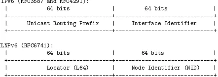
We have implemented a prototype of ILNPv6 (ILNP as a superset of IPv6) in Linux kernel v3.9.0. L64andNIDvalues are encoded into the IPv6 address space – see Figure 1 [6]. The top 64 bits,L64, have the same syntax and semantics as a routing prefix in IPv6. Its value is obtained from a normal IPv6 Router Advertisement (RA). The lower 64 bits, NID , has the same syntax as the IPv6 Interface Identifier, but different semantics i.e. it represents a whole node, not a specific interface of the node, and is not used for routing in the core network. For convenience, our implementation
uses an NID value derived from the MAC address of the
first active interface. To improve security and privacy, the NIDvalues could be randomly generated similar to a privacy extensions for IPv6 addresses [21].
IPv6 (RFC3587 and RFC4291):
| 64 bits | 64 bits |
+---+---+
| Unicast Routing Prefix | Interface Identifier |
+---+---+
ILNPv6 (RFC6741):
| 64 bits | 64 bits |
+---+---+
| Locator (L64) | Node Identifier (NID) |
[image:2.612.319.540.526.604.2]+---+---+
Figure 1: Encoding of NID and L64 values into the IPv6 address bits. An ILNPv6 L64 value has the same syntax and semantics as an IPv6 routing pre-fix. An ILNPv6 NID value has the same syntax as an IPv6 Interface Identifier, but differentsemantics
as it represents thenode not aninterface.
The Linux system library (eglibcfor handling names from
/etc/hosts) and kernel code were modified to enable mobility
3.1
Name resolution
Rendezvous concerns how correspondent nodes initiate connections to a mobile host. ILNP can use DNS [5, 8] just like IPv6 and MIPv6. However, our focus here is to study the handoff performance, so we ignore DNS and use a mod-ified version of/etc/hostsfor mapping names to initialNID andL64values.
The list of ILNPv6 hosts along with theirNID and L64 value is presented in the/etc/hostsfile with a new syntax:
L64|preference,NID hostname
The getaddrinfo() networking API is modified to
inter-pret this new entry in the file. Whengetaddrinfo()detects a “,” in an address field, it extracts an Identifier, Locator and preference value (ignored for now) and passes them to the kernel via the Netlink Socketto store in an Identifier-Locator Vector (I-LV) cache. Then, an ILNPv6 ‘address’, which looks similar to a traditional IPv6 address, is built from those NID and L64 value and is returned to the caller. This allows the current socket() API to be re-used. Hence, well-behaved legacy applications (those that use the socket descriptor only, and do not use address bits for application state) should work with ILNPv6 just like they would with IPv6. By checking the I-LV cache, the kernel can identify if the providedsockaddrstructure contains an IPv6 address or ILNPv6 address. Internally, a new ‘is ilnp’ flag is used in the socket data structure (struct sock) so that the kernel can distinguish ILNPv6 sockets from IPv6 sockets.
3.2
ILNPv6 packets
For each incoming and outgoing packet, the kernel must be able to detect if it is an ordinary IPv6 packet or an ILNPv6 packet. For outgoing packets, the destination IP address is checked against the I-LV cache. If the address is found in the cache, the destination is an ILNP node. The sender then adds a nonce value [7] and, for convenience in our prototype implementation only, sets the flowlabel in the IPv6 header to 0x0800. For each incoming packet, the flowlabel is checked. If the flag is set to 0x0800, then this is an ILNP packet, and additional operations for ILNPv6 are performed including validation of theNIDand L64of the sender, checking the nonce value, and updating information in the ILNP
Com-munication Cache (ILCC) which is, effectively, a table of
ILNP sessions.
3.3
ILNP Communication Cache (ILCC)
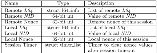
The ILCC stores information of all active ILNPv6 com-munication sessions of the mobile host. It is implemented in the kernel as a combination of a hash table and linked list. Important members of each ILCC element are shown in Table 2. Each element contains remote and localL64 val-ues implemented as a linked list ofstruct l64 info, which has important members shown in Table 3. The nonce value rep-resent a unique communication session. In this initial eval-uation, we use thebidirectionalnonce value – both commu-nication ends use the same nonce value. The sender would use the nonce value presented in the ILCC or generate a new one, if the value is not set (i.e. a new session is initiated). For a new session, the receiver would obtain the nonce value from the nonce option in the first received packet. For each session, there is only one ‘active’ localL64and one ‘active’ remoteL64at the same time. The ‘active’ local/remoteL64 is changed when handoff, see Section 3.4 for more details.
Table 2: Important members of an ILCC entry.
Name Type Description
RemoteL64 struct l64 info List of remoteL64
RemoteNID 64-bit int Value of remoteNID
Remote Nonce 32-bit int Remote nonce of this session
LocalL64 struct l64 info List of localL64
LocalNID 64-bit int Value of localNID
Local Nonce 32-bit int Local nonce of this session
Session Timer struct timer list Timer to clear nonce values
[image:3.612.315.570.79.166.2]after session timeout
Table 3: Important members of struct l64 info.
Name Type Description
L64value 64-bit int Value ofL64
flag 32-bit int status of this L64 (active,
valid, aged, or expired)
lifetime 32-bit int Duration that thisL64 stay
valid
Timer struct timer list Timer to set flag to ‘expired’
for staleL64
3.4
Handoff Management
In ILNP, handoff is implemented by manipulating the dy-namic bindings betweenNIDandL64values. A mobile host detects a location change when receiving a new prefix i.e. it moves to a new network and picks up a new prefix from the IPv6 RA sent by a new access router. Once a new prefix is received, a new ILNPv6 address is configured. For IL-NPv6, the new address is built from a new prefix (L64) and theNID, not the interface identifier like ordinary IPv6 ad-dresses. The mobile node would then notify a change ofL64 value using Locator Update (LU) message [4] to all active correspondent nodes listed in the ILCC.
There are two types of handoff in ILNP: hard handoff and soft handoff. For hard handoff, the mobile host always uses onlyone L64value at a time. Soft handoff allows the mobile host to use more than oneL64values (e.g. an ‘active’ one and a ‘valid’ one), which means that a mobile host can belong to two IP networks simultaneously.
In Figure 2, once the mobile host, X, obtains a newL64 value (L2X), it updates the current ‘active’ localL64value
in ILCC and could (i) set the flag of previously activeL64 (L1X) to ‘aged’ – hard handoff; or (ii) maintain bindings
with bothL1X andL2X when it stays in an overlap region
between the two networks (e.g. through radio-cell coverage) i.e. the flag of the previously activeL64(L1X) is changed to
‘valid’ – soft handoff. With hard handoff packet loss could occur because the correspondent node, Y, still using the old L64value, where the packets sent to the ‘aged’ destination L64value. With soft handoff, the packet loss during handoff is minimised, and may be close to zero because the previous L64 value is still ‘valid’ for the mobile node, as long as it stays in the overlap area. For Y, once a LU is received, the ‘active’ destinationL64would be updated to the new value and the LU-ACK would be sent back to the sender.
3.5
Modification of UDP
X Y
<IP: L1X, LY> <IP: LY, L1X>
<IP: L2X, LY>
locator change
triggered LU (L2
X)
<IP: LY, L2X>
LU-ACK (L
2X)
Hard handoff
X Y
<IP: L1X, LY> <IP: LY, L1X>
<IP: L1X, LY> <IP: L2X, LY>
locator change
triggered LU (L2
X)
<IP: LY, L2X>
<IP: L2X, LY>
LU-ACK (L
2X)
Soft handoff Handoff
Delay
Handoff Delay
P
os
si
b
le
p
ac
ke
t l
os
[image:4.612.100.509.51.182.2]s
Figure 2: A comparison of hard handoff and soft handoff. Once a mobile node X enters a new network, it receives a new L64 value:L2X. In hard handoff (left), X simply switch to use the new L64 (L2X) and
stops using the old one (L1X). Packet loss (red/dotted arrows) could occur until the correspondent node Y
learns the updated L64 value, from the Locator Update (LU) sent by X, subsequent packets will be accepted (green/dashed arrows). In soft handoff (right), X uses bothL1X and L2X simultaneously until it receives the
LU-ACK sent by Y, minimising packet loss during the handoff.
be used for building an IP header are up-to-date (i.e. stale values after a location change are not used). The kernel al-ways selects the current ‘active’L64value from the ILCC to derive the source/destination IPv6 address instead of using the values provided from user space (passed to the socket() call after using getaddrinfo()), which may now be stale.
4.
EVALUATION
We examine the handoff performance comparing hard hand-off and soft handhand-off, by considering: (i) the impact on UDP application flows; and (ii) the handoff mechanism based on the LU/LU-ACK exchange.
4.1
Experiment Configuration
Our testbed is configured as in Figure 3. All connections
are wired Ethernet 1Gbps connections: we emulate WiFi
network and 3G network behaviour in terms of loss and delay by usingnetem1
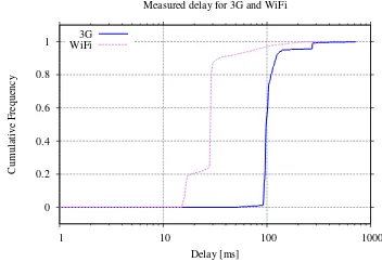
[image:4.612.316.562.272.384.2], a popular Linux network emulation tool. Table 4 summarises the characteristic of the WiFi network and the 3G network, and Figure 4 presents the cumulative frequency distribution of the one-way delay. These profiles were obtained from realpingmeasurements of our local office WiFi network and a 3G network from an Apple iPhone 5, over a 40 minute period for each network.
Table 4: Network characteristics of WiFi and 3G.
Connection Packet One-way Delay [ms]
Loss [%] mean stdev 95% 99%
WiFi 0.26 33 26 76 180
3G 10.10 112 50 140 276
The routers, R1 and R2, are unmodified Linux machines running radvd2
to announce prefixes for the site networks
L1, L2 and L3. To allow the mobile host to pick up new prefixes quickly once it enters a new network, we configure radvd to generate RAs every 1s-2s.
We used a simple UDP/IPv6 application to generate two kinds of traffic between H1 and H2: Voice over IP (VoIP) 1
http://www.linuxfoundation.org/collaborate/ workgroups/networking/netem/
2
http://http://www.litech.org/radvd/
R1
H1 site network L1
site network L2
H2 site network L
3
H2
R2
R router
H physical device / host
H2 Emulated Loss and
Delay for WiFi
Emulated Loss and Delay for 3G
Figure 3: The topology for the experiment. The
hosts H1 and H2 reside in different networks, with Locator values ofL1andL2, respectively. The green / dashed arrows identify movements of H2 between site networks generating a handoff.
0 0.2 0.4 0.6 0.8 1
1 10 100 1000
Cumulative Frequency
Delay [ms] Measured delay for 3G and WiFi
3G WiFi
Figure 4: The cumulative frequency distribution of one-way delay of WiFi network and 3G network.
flows and streamed video flows. The VoIP flows are gener-ated based on characteristics of Skype traffics [9, 12], using a packet size of 300 bytes to generate a 64kbps flow. We use 1 Kbyte packets to generate 250 kbps video (ViIP) flows, as an emulation of mobile YouTube traffic [27]. For both flows, an acknowledgement is sent for each packet, so, the sender can evaluate loss.
[image:4.612.345.521.463.584.2]was emulated by turning interfaces on and off between the emulated WiFi network and the emulated 3G network. The handoff is triggered when a new interface of H2 comes up and receives a new L64 from an IPv6 RA. The handoff is completed by an LU/LU-ACK handshake as: (i) H2 updates
new L64 value to H1 by sending a LU messages, (ii) H1
responds with an LU-ACK to H2. If H1 did not receive the LU-ACK within in 1 second, the LU was retransmitted. The retransmissions stop after 5 attempts. The handoffs were made every 9 seconds, with 5 seconds in the overlap area (i.e. both interfaces of H2 were on).
Each flow was 75 seconds long. We performed 10 repeti-tions for each of the scenarios above using hard handoff and soft handoff.
4.2
Results
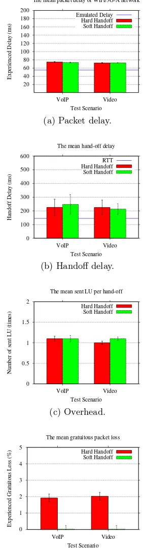
Packet delay is the application level packet delay. This
is the time taken to deliver a packet to another end host. The values are measured using half of the round-trip time (RTT/2) of each acknowledged packet, as the path was sym-metric. The closer this is to the natural value, the better. (Figure 5a.)
Handoff delayis the time taken for a mobile host to
com-pletely switch to use a new L64, i.e. the duration of the LU/LU-ACK handshake. The closer this value is to the RTT, the better. (Figure 5b.)
Overheadis the number of LU / LU-ACK handshakes that
are required in order to complete a handoff process. The closer the number is to 1, the better. (Figure 5c.)
Gratuitous packet lossis the application level packet loss
additional to the natural network loss, i.e. loss caused by the handoff mechanism. The values are the differences of overall loss (calculated from the number of sent packets and the number of acknowledged packets) and natural loss (see below). The closer this is to zero, the better. (Figure 5d.)
The main finding is that, for our experimental configu-ration, soft handoff minimises gratuitous loss (Figure 5d), while having similar performance to hard handoff in terms of packet delay (Figure 5a), handoff delay (Figure 5c), and signalling overhead (Figure 5c).
Figure 5d shows that gratuitous packet loss was min-imised, and was almost zero. Hard handoff incurred gratu-itous packet loss, as expected from our discussion in Section 3.4 and Figure 2, as some packets were transmitted with the incorrect L64 value while the LU/U-ACK handshake was in-complete. As the mobile host started in the WiFi network and handed-off every 9 seconds, it spent 36 seconds (48%) in the 3G network and 39 seconds (52%) in the WiFi network. Hence, the ‘natural’ loss is calculated from the Eqn. (1), use
LossW iF i= 10.10 andLoss3G= 0.26 (from Table 4), giving
a value of 4.98%.
Loss= (52LossW iF i/100) + (48Loss3G)/100) (1)
The measured delay, for both hard handoff and soft hand-off, is slightly higher than the emulated values in every case by (∼20ms) (see Figure 5a) due to the cumulative processing
delays in the end systems and netem. The ‘natural’ delay can also be calculated from Eqn. (1): by replacingLossW iF i
withDelayW iF i(33ms) andLoss3GwithDelay3G(112ms),
the natural delay is 70.92ms.
The minimum value of the mean handoff delay (Figure 5b) would be the RTT – 66ms when handing off to WiFi (4 times) and 224ms when handing off to 3G (4 times). So,
20 40 60 80 100 120 140 160 180 200
VoIP Video
Experienced Delay (ms)
Test Scenario
The mean packet delay of WiFi/3G-A network
Emulated Delay Hard Handoff Soft Handoff
(a) Packet delay.
0 100 200 300 400 500 600
VoIP Video
Handoff Delay (ms)
Test Scenario The mean hand-off delay
RTT Hard Handoff Soft Handoff
(b) Handoff delay.
0 0.5 1 1.5 2
VoIP Video
Number of sent LU (times)
Test Scenario The mean sent LU per hand-off
Hard Handoff Soft Handoff
(c) Overhead.
0 1 2 3 4 5
VoIP Video
Experienced Gratuitous Loss (%)
Test Scenario The mean gratuitous packet loss
Hard Handoff Soft Handoff
[image:5.612.360.501.62.599.2](d) Gratuitous packet loss (Overall loss – Natural loss).
Figure 5: Performance of hard and soft handoff. Er-ror bars at 95% confidence from 10 runs. Horizon-tal/bue lines are ‘natural’ values (see Section 4.2).
RTT), and we can see that the mean number of LUs sent (i.e. handovers attempted) is low (Figure 5c).
5.
CONCLUSION
Our in-kernel Linux implementation of ILNPv6 shows that soft handoff with ILNP minimises gratutous packet loss dur-ing handoff, while maintindur-ing similar performance to hard handoff in terms of handoff delay, application level packet delay and signalling overhead. We believe that ILNPv6, with soft handoff, could work well in a range of wireless net-work scenarios including WiFi netnet-works and 3G netnet-works (see our previous work [26]).
The ILNP mobility model is purely end-to-end, not requir-ing middlesboxes, proxies or tunnellrequir-ing, and has low over-head. Not requiring middleboxes or proxies also obviates performance bottlenecks, single points of failure and targets for attack by malicious users.
For the future, we plan to complete the ILNPv6 prototype and test against various existing mobility solutions, includ-ing Mobile IPv6 and, in a range of scenarios and includinclud-ing with the use of real applications.
6.
REFERENCES
[1] A. Achour, B. Kervella, and G. Pujolle. SHIM6-based mobility management for multi-homed terminals in heterogeneous environment. InWOCN 2011 - 8th Intl. Conf. Wireless and Optical Communications
Networks, pages 1–5, May 2011.
[2] R. Atkinson, S. Bhatti, and S. Hailes. ILNP: Mobility, Multi-homing, Localised Addressing and Security Through Naming.Telecommunication Systems, 42(3):273–291, Dec 2009.
[3] R. Atkinson, S. Bhatti, and S. Hailes. Evolving the Internet Architecture Through Naming.IEEE JSAC, 28(8):1319–1325, Oct 2010.
[4] R. Atkinson and S. N. Bhatti. ICMP Locator Update Message for the Identifier-Locator Network Protocol for IPv6 (ILNPv6). RFC 6743, IRTF, Nov 2012. [5] R. Atkinson and S. N. Bhatti. Identifier-Locator
Network Protocol (ILNP) Architectural Description. RFC 6740, IRTF, Nov 2012.
[6] R. Atkinson and S. N. Bhatti. Identifier-Locator Network Protocol (ILNP) Engineering Considerations. RFC 6741, IRTF, Nov 2012.
[7] R. Atkinson and S. N. Bhatti. IPv6 Nonce Destination Option for the Identifier-Locator Network Protocol for IPv6 (ILNPv6). RFC 6744, IRTF, Nov 2012.
[8] R. Atkinson, S. N. Bhatti, and S. Rose. DNS Resource Records for the Identifier-Locator Network Protocol (ILNP). RFC 6742, IRTF, Nov 2012.
[9] D. Bonfiglio, M. Mellia, M. Meo, D. Rossi, and P. Tofanelli. Revealing Skype traffic: when
randomness plays with you. InProc. SIGCOMM 2007,
pages 37–48, New York, NY, USA, 2007. ACM. [10] B. Carpenter. Architectural Principles of the Internet.
RFC 1958, IAB, Jun 1996.
[11] B. E. Carpenter. IP Addresses Considered Harmful.
SIGCOMM Comput. Commun. Rev., 44(2):65–69,
Apr. 2014.
[12] K. Chen, C. Huang, and C. Huang, P.and Lei. Quantifying Skype user satisfaction. InProc.
SIGCOMM 2006, pages 399–410, New York, NY,
USA, 2006. ACM.
[13] A. Dhraief and N. Montavont. Toward Mobility and Multihoming Unification - The SHIM6 Protocol: A
Case Study. InIEEE WCNC 2008 - Wireless Comms.
and Networking Conf., pages 2840–2845, March 2008.
[14] D. Farinacci, V. Fuller, D. Meyer, and D. Lewis. The Locator/ID Separation Protocol (LISP). RFC 6830, IETF, Jan 2013.
[15] S. Gundavelli, K. Leung, V. Devarapalli,
K. Chowdhury, and B. Patil. Proxy Mobile IPv6. RFC 5213, IETF, Aug 2008.
[16] R. Hinden and S. Deering. IP Version 6 Addressing Architecture. RFC 4291, IETF, Feb 2006.
[17] E. Ivov and T. Noel. An experimental performance evaluation of the IETF FMIPv6 protocol over IEEE
802.11 WLANs. InProc IEEE WCNC 200, volume 1,
pages 568–574, April 2006.
[18] R. Koodli. Mobile IPv6 Fast Handovers. RFC 5568, IETF, July 2009.
[19] R. Moskowitz, P. Nikander, P. Jokela, and T. Henderson. Host Identity Protocol. RFC 5201, IETF, Apr 2008.
[20] M. Mudassir Feroz and A. Kiani. SHIM6 Assisted Mobility Scheme, an intelligent approach. InIEEE CCNC 2013 - Consumer Comms. and Networking
Conf., pages 725–728, Jan 2013.
[21] T. Narten, R. Draves, and S. Krishnan. Privacy Extensions for Stateless Address Autoconfiguration in IPv6. RFC 4941, IETF, Sep 2007.
[22] P. Nikander, T. H. (Ed), C. Vogt, and J. Arkko. End-host mobility and multihoming with the host identity protocol. RFC 5206, IETF, Apr 2008. [23] E. Nordmark and M. Bagnulo. Shim6: Level 3
Multihoming Shim Protocol for IPv6. RFC 5533, IETF, Jun 2009.
[24] C. Perkins. IP Mobility Support for IPv4, Revised. RFC 5944, IETF, Nov 2010.
[25] C. Perkins, D. Johnson, and J. Arkko. Mobility Support in IPv6. RFC 6275, IETF, Jul 2011. [26] D. Phoomikiattisak and S. N. Bhatti. Network Layer
Soft Handoff for IP Mobility. InProc. PM2WH2N
2013 - 8th ACM Wrkshp. Perf. Monitoring and Measurement of Heterogeneous Wireless and Wired
Networks, pages 13–20, Nov 2013.
[27] J. Ramos-munoz, J. Prados-Garzon, P. Ameigeiras, J. Navarro-Ortiz, and J. Lopez-soler. Characteristics of mobile youtube traffic.Wireless Communications, IEEE, 21(1):18–25, February 2014.
[28] A. Rodriguez Natal, L. Jakab, M. Portoles,
V. Ermagan, P. Natarajan, F. Maino, D. Meyer, and A. Cabellos Aparicio. LISP-MN: Mobile Networking Through LISP.Wireless Personal Communications, 70(1):253–266, 2013.
[29] H. Soliman, C. Castelluccia, K. ElMalki, and L. Bellier. Hierarchical Mobile IPv6 (HMIPv6) Mobility Management. RFC 5380, IETF, Oct 2008. [30] Z. Zhu, R. Wkaikawa, and L. Zhang. A Survey of