Abstract— This paper deals with the algorithm for seismic resistant design according to configuration of shear wall of Hanok. Hanok is traditional Korean building style, which consists of timber frame structure. In recently, Hanok has been developed as a new-styled structure to accommodate the modern style of urban life. However, a structural analysis for seismic resistant design of Hanok needed to be proposed after a series of earthquakes in Korea, that is, 2016 and 2017 earthquakes in southeast area of Korean peninsula. The most important thing in seismic design is to ascertain the torsional movement which is generated by the eccentricity, caused by the difference between the center of mass and the center of rigidity. For this reason, the authors suggest the method that the eccentricity can be calculated easily by defining the center of rigidity of Hanok according to shear wall configurations. These processes are converted into Excel charts to make an automated structural design tool.
Index Terms—Hanok, center of mass, center of rigidity, seismic design, eccentricity.
I. INTRODUCTION
ANOK is well-known for traditional Korean building style remaining architecture more than 2,000 years in Korea. The traditional Hanok, which is shown in Fig. 1(a) is built on a scale of no more 5~6(m) per frame interval. The structure of Hanok has been secured structurally safety and stability by having the construction of columns, beam, Dori and the bracket design for a long time. Nowadays, Hanok has been studied a various of structure type such as a long spanning and multi-storied type to accommodate using of public program for offices, city hall as well as the traditional house as shown in Fig. 1(b) However, the problem that has conducted to the development of Hanok is that it must consider seismic resistant design like modern architecture due to enact building Act for safety after a series of magnitude 5.0 or greater earthquakes in 2016 and 2017.
Structure design for traditional timber frame has performed mainly the method evaluating section size under the vertical load until now. If the information of span and vertical loads even though they are not a structural expert, all of section sizes for Hanok can be easy to calculate by using the automated design tool, which suggested by Kim [4].
On the other hand, the seismic design method for the
Manuscript received January 4, 2019; revised January 17, 2019. This work was supported by a grant (19AUDP-B128638-03) from Urban and Architecture Research Program funded by Ministry of Land, Infrastructure and Transport Affairs of Korean Government and Myongji University.
Yeong-Min Kim is an Professor, College of Architecture, Myongji University, Yongin, Republic of Korea (corresponding author to provide phone: 82-31-330-6490; fax: 82-31-330-6487; e-mail: ymkim@ mju.ac.kr). Bum-Soo Park is an graduate Student, Department of Architecture, Myongji University, Yongin, Republic of Korea (e-mail: bum9824@ naver.com).
traditional wooden structure is difficult to evaluate under the lateral loads and it is not easy for architect who designs Hanok because only the structural expert can do it. If the structural process can develop easily not only calculating under the vertical loads but also evaluating under the lateral loads, the development of traditional timber frame can be much more useful, convenient and structural stable.
(a) Traditional Hanok
[image:1.595.321.533.254.514.2](b) New-Styled Hanok
Fig. 1. Traditional Hanok and new-styled Hanok
Many researches for evaluating the timber frame structure under the vertical and lateral loads have been carried out. Researches are divided into several categories.
First, Kim [1] suggested an interpretation method through analysis of structural characteristics of Hanok. Kim et al. [2], [3], [4] studies the member size evaluation under the vertical loads. Specifically, Kim [3], [4] invented a structural tool for calculating the main member of timber frame that includes column, beam, girder by converting the calculation process into an automated step. Furthermore, after an automated step invented, it suggested a section table. Those studies are closely related to this process for structure design tool.
To investigate structural behavior of timber frame under the lateral loads, various researches conducted. Most studies carried out evaluation the method and procedure from the frame modeling test and derived the initial stiffness values. The stiffness values in beam and girder direction means the restoring value. Many frame model experiments have been conducted to evaluate stiffness of each direction. Lee et al. [5] showed lateral capacity of one direction through static loads test. Also, Lee et al. [6] studies the beam-direction capacity and Lee [7] carried out the static test for analysis of the dori direction, which is girder direction, and investigated the
The Algorithm for the Development of
Seismic Resistant Design Tool for Hanok
Yeong-Min Kim, Bum-Soo Park, Member, IAENG
stiffness of frame. In Japan, Suzuki et al. [8] analyzed restoring force characteristics by changing rotation angle through the frame model test.
To develop seismic performance of Hanok, shear wall stiffness value is required because seismic performance of timber frame can be enhanced by installing shear walls on the frame. Hong et al. [9] distinguished between a single frame model from one installing shear wall. And then, he compared the stiffness value from results. In addition, Kim et al. [10] used seismic capacity evaluation index to confirm performance of existing traditional timber buildings. They surveyed buildings and configuration of shear wall.
As a specific study for shear wall of Hanok, Disaster laboratory [11], [12] developed seismic capacity evaluation manual for traditional frame structure and tried to various experiments. Also, for investigating the behavior of torsional movement due to the eccentricity, Cho et al. [13] studies relationship and mechanism between designed eccentricities with torsion.
In this study, the algorithm for seismic resistant design tool has been studied. The main concept of algorithm is to design configuration of shear wall and it aims to evaluate the safety of torsional movement for Hanok.
II. THE PROCESS OF ALGORITHM
As mentioned above, the seismic resistant design has to consider the configuration of lateral resistance elements such as shear wall or brace, which is shown in Fig. 2. As the seismic capacity of building is depending on the placement of shear wall, the placement method is the most important process.
In this regard, the algorithm shows the procedure for seismic design by calculating and deriving the most suitable configuration of shear wall according to plan shape. And then, it evaluates the seismic capacity of building designed through calculating the eccentricity according to configuration.
The step of algorithm is as follows, which is shown in Fig. 3.
1) Select a plan type of Hanok to be designed by architect, which is classified into five categories.
2) To calculate the center of mass of selected plan type, enter dimensions of the beam and dori direction, which is X and Y directions.
3) Define the lateral resistance elements. The proposed items are frame type and shear wall type, and additional stiffness values can be adjusted according to user design option and coefficient information.
4) Deploy the shear wall with defined lateral resistant element, it can be placed for each bay in the X and Y directions and the center of rigidity is calculated by the input information.
5) Check the eccentricity through the process from step (1) to (4). The eccentricity will be calculated by the difference between the center of mass, which is center of the plan shape and the center of rigidity, which is derived from the configuration of the lateral resistant element. If the each of centers isdifferent, the torsional movement that caused by the eccentricity will be increased. Therefore, to prevent the torsional movement, it is necessary to make each center as close as possible. 6) If the calculated eccentricity is not satisfied at step (6) in
flowchart of algorithm, it can be modified as suitable as possible after going back to step (3) through modifying the placement of shear wall or changing the definition of
[image:2.595.346.506.71.184.2]elements.
Fig. 2. Hanok styled shear wall. Shear wall consists of soil wall with horizontal intermediate member called Inbang and has door opening.
Fig. 3. The algorithm for seismic resistant design of Hanok
III. CALCULATION OF THE CENTER OF MASS
The seismic force of building is converted into weight and acceleration, the center of mass is the point where seismic force is applied. The points of each floor is calculated by the dimension of X and Y directions.
In order to develop the calculation process of center of mass that is suitable Hanok, we defined five representative plan shapes as L type, linear type, C type, T type, closed type, and then, made the equation for center of mass. Equation (1) and (2) require the dimensions and areas in the X and Y directions. In (1) and (2), is the area of plan and is the median of the X direction dimension. is the median of the Y direction dimension.
Fig. 4. The process of center of mass calculation in L type plan
IV. CALCULATION OF THE CENTER OF RIGIDITY
The center of rigidity is an important point where the structure resists against seismic force. As noted before, the lateral resistant element that makes center of rigidity can be classified shear wall with brace and column. The center of rigidity that calculated only by columns is not different the center of mass because the arrangement of column is predetermined in plan type.
On the other hand, the shear wall is most crucial element for resisting against seismic force and it can move the center of rigidity according to the placed position. In addition, it can change the stiffness depending on material and shear wall types. The table as follows indicates the option for which the stiffness element can be selected.
A. Beam direction frame type
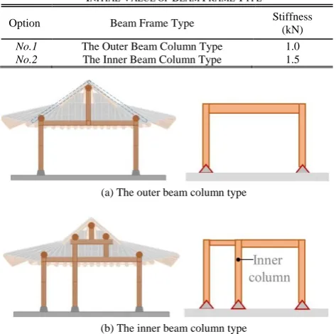
The beam direction of timber frame structure has different stiffness depending on the type of outer and inner column as shown in Fig. 5(a), (b). According to Hong et al. [9], the inner beam column type is evaluated to have about 1.5 times the seismic resistant performance than the outer beam column type due to additional buttress. Using the correlation, we set the initial value for the frame type in Table I.
TABLEI
INITIAL VALUE OF BEAM FRAME TYPE
Option Beam Frame Type Stiffness (kN)
No.1 The Outer Beam Column Type 1.0
No.2 The Inner Beam Column Type 1.5
(a) The outer beam column type
(b) The inner beam column type Fig. 5. Frame type of beam direction
B. Shear wall type
The shear wall of traditional timber structure is generally constructed using soil and tree branches. In addition, when braces are installed, the stiffness of wall can be increased compared to the shear wall without brace, it also can be adjusted according to the opening portion in one frame. The
stiffness values required for the experiment are given in Disaster laboratory [11], [12]. Considering those information, we set the initial value for the shear wall type in Table Ⅱ.
TABLEⅡ
INITIAL VALUE OF SHEAR WALL TYPE
Option Shear wall Type Stiffness (kN)
No.1 Full-filled wall 6.6
No.2 Half-filled wall 3.6
No.3 The Inbang styled wall 4.4
C. Materials of Shear Wall
As mentioned previously, the stiffness of wall depends on the filled wall material. Traditional Hanok consists of soil wall, but new-styled Hanok can be used various materials such as concrete, glass, board and brick. According to this change, the shear wall can be adjusted by multiplying the wall stiffness value by a factor that depends on the material shown in Table Ⅲ.
TABLEⅢ
MATERIAL TYPE OF SHEAR WALL
Material Wall Type Modification Factor
Soil Infilled Soil wall 1.0
Wood Wood panel 1.2
Board Hardboard panel 1.5
Concrete Concrete wall 2.0
The center of rigidity of X and Y directions and each center were calculated by using (3) and (4). is total stiffness of shear wall placed in X direction and is total stiffness of shear wall placed in Y direction, which is shown in Table Ⅱ. and are the distance from the origin in the X and Y direction. For example, in order to calculate the center of X direction rigidity, that is, the distance value from origin is required and it is multiplied by that is the stiffness value placed on the Y direction. And it divides into the sum of stiffness, which is shown in Fig. 6.
V. EVALUATE ECCENTRICITY
The eccentricity of building is calculated by using (5), which subtract and that is the center of rigidity from and that is the center of mass. As shown in Fig. 7(b), when the shear wall is placed, the center of rigidity will move toward walls. that is, it can be different from the center of mass. As a result, eccentricities occur as shown in Fig. 7(c).
As the seismic force generates randomly among X and Y directions, the eccentricity must be considered in both directions. It should be calculated as small as possible. Also, the allowable condition is limited to less than or equal to 5% of the dimension, which is direction applied seismic force. This is because torsional moment is generated by the amount of eccentricity as shown in Fig. 7(d). The less eccentricity is the better.
(a) Coincidence of center of mass with the center of rigidity
(b) Movement of center of rigidity from the center of mass by installation of shear wall
(c) Resultant eccentricity due to difference between center of mass and center of rigidity
[image:4.595.305.546.233.466.2](d) Torsional movement generated by the eccentricity under seismic force Fig. 7. Eccentricity through shear wall arrangement
VI. CONCLUSION
In this study, the algorithm for seismic resistant design of Hanok was suggested. The process of algorithm was planned focusing on elements of seismic force.
The main concept is the seismic resistant design using the eccentricity, which is based on the difference between the center of mass where the seismic force applied and the center of rigidity due to the configuration of shear wall.
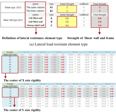
The above process was converted into Microsoft Excel as an automated design tool. As shown in Fig. 8(a), the user can choose the option that defined the stiffness and type. And the center of rigidity will be calculated by arranged shear walls, which is shown in Fig. 8(b) As a result, it is possible to confirm the eccentricity and to evaluate the safety from torsional movement.
(a) Lateral load resistant element type
(b) Calculation of center of rigidity both in X and Y directions
(c) Calculation of eccentricity
Fig. 8. The Development of MS Excel software design tool
REFERENCES
[1] Y. M, Kim, “What is the Characteristics of Structural Analysis of Hanok?", Journal of the Architectural Institute of Korea, Vol.57, No.4, April. 2013.
[2] Y. M, Kim, J. H, Kim “A Study on the Development of Section Table for Lateral Members of Hanok", Journal of the Architectural Institute of Korea: Structure & Construction, Vol.30, No.2, pp. 37-44, Feb. 2014.
[image:4.595.302.554.491.624.2]Institute of Korea: Structure & Construction, Vol.31, No.11, pp. 21-28, Nov. 2015.
[4] Y. M. Kim, “Development of Automated Structural Design Tool for Horizontal Members of Hanok " Journal of the Architectural Institute of Korea : Structure & Construction, Vol.33, No.4, pp. 21-28, April. 2017.
[5] Y. W. Lee, J. K. Hwang, J. S. Hwang “Evaluation of Lateral Capacity Model of Traditional Wooden Structural Frame " Journal of the Architectural Institute of Korea : Structure & Construction, Vol.15, No.6, pp. 211-217, Dec. 2013.
[6] Y. W. Lee, B. S. Bae, S. G. Hong, J. K. Hwang, S. J. Jung, N. H, Kim, "An Analytical Modeling of the Beam-Direction Frame of Traditional Wood Structure System", Journal of the Architectural Institute of Korea : Structure & Construction, Vol.22, No.3, pp. 29-36, Mar. 2006. [7] Y. W. Lee, S. G. Hong, J. K. Hwang, B. S. Bae, " Capacity of Lateral
Load Resistance of Dori-Directional Frame with Jangbu-connection in Traditional Wood Structure System", Journal of the Architectural Institute of Korea : Structure & Construction, Vol.23, No.2, pp. 29-36, Feb. 2007.
[8] Suzuki Y, Maeno M, "Structural Mechanism of Traditional Wooden Frames by Dynamic and Static Tests", Journal of the Structural Control Health Monitoring, pp. 508-522, Dec. 2005.
[9] S. G. Hong, P. S. Lee, "Behavior of traditional wood frames under earthquake loading", Earthquake Engineering Society of Korea Sep. 2000.
[10] H. W. Kim, J. H. Lee, B. C. Park, W. H. Yi, "Seismic Capacity Evaluation of the Traditional Wooden Structure using Capacity Spectrum and Seismic Index", Journal of the Architectural Institute of Korea : Structure & Construction, Vol.26, No.9, pp. 3-14, Sep. 2010. [11] Disaster Laboratory, "Performance Stiffness Reduction Test Wall and
Joint in Wood Structure", National Disaster Management Research Institute, pp. 139-239, Dec. 2010.
[12] Disaster Laboratory, "Development of the Seismic Capacity Evaluation Manual on Wooden Structures", National Disaster Management Research Institute, pp. 75-154, Dec. 2010.