611
©IJRASET: All Rights are Reserved
A Study of Effect of Seismic Analysis on High Rise
Building by using Shear Wall in ETABS
Ms. Kaveri K. Kothmire1, Mr. Akshay S. Metkar2, Mr. Kunal B. Nifade 3, Mr. Mayur A. Kadbhane4, Prof. Manoj V. Rathod5
1, 2, 3
B.E. Students, Assistant Professor, Department of civil Engineering, Shatabdi Institute of Engineering and Research, Agaskhind, Sinnar, Nashik, Maharashtra, India.
Abstract: Earthquakes Reinforced concrete framed building are capable both the vertical and horizontal load acting on them. However, when building is tall, it is difficult to workout sizes of beams and columns. There is lot of clogging at these joint and it is difficult to place and vibrate concrete at these places which does not contribute the safety of building. These practical difficulties call for introduction of shear wall.
Shear wall has very high in plane strength and stiffness which can be used to simultaneously resist large horizontal loads and supports gravity loads. Therefore, incorporations of shear wall have become assured in multi-storey building built in region likely to experienced earthquake of high intensity or high winds. There are lots of literatures available to design and analyze the shear wall.
However, the decision an arrangement of shear wall in multi-storey building is not much discuss in literature, in these studies; therefore, main objective is to determine the position of shear wall in multi-storey building. An earthquake load is applied to a building of 20 stores located in various zones.
The analysis is performing using ETABS software. Axial forces, shear force, bending moment, storey displacement and time period are computed and location of shear wall is established.
Keywords: ETABS (2016), Response Spectrum Analysis, Seismic Responses and Shear wall.
I. INTRODUCTION
ETABS stands for “extended three-dimensional analysis of building system”. ETABS is a sophisticated, yet easy to use, special purpose analysis and design program developed specifically for building system. ETABS 2016 features and an intuitive and powerful graphical interface coupled with unmatched modeling, analytical, design and detailing procedure, all integrated using a common data base. All though we can easy simple structures, ETABS can also handle largest most complex buildings models, including wide range of nonlinear behaviors necessary for performance base design, making it the tool of choice for structural choice in building industry. Page Layout ETABS is the solution, whether you are designing a simple 2d frame or performing a dynamic analysis of a complex high-rise that utilizes non-linear dampers.
Feature of ETABS 1) Modeling 2) Analysis 3) Design 4) Detailing
Also, different loading can be identified using ETABS such as Earthquake Load, Wind Load etc.
A. Shear Walls
In structural engineering, a shear wall is a vertical element of a seismic force resisting system that is designed to resist in-plane lateral forces, typically wind and seismic loads.
Shear wall is a structural member used to resist lateral forces i.e. Parallel to the plane of the wall. For slender walls where the bending deformation is more, shear wall resists the loads due to cantilever action. In other words, shear walls are vertical elements of the horizontal force resisting system.
612
©IJRASET: All Rights are Reserved
Based on type of material used, shear walls are classified into following types. 1) Reinforced concrete shear wall
2) Concrete block shear wall 3) Steel shear wall
4) Plywood shear wall 5) Mid-ply shear wall
II. OBJECTIVES
A. To determine optimum location of shear wall in RCC structure.
B. To suggest optimum geometry of shear wall with belt result against stability. C. To increase stability of RCC structure against the effect of lateral force system. D. To determine relative storey displacement in case of multiple high-rise building.
E. To analyze the various results under the effect of shear wall in RC structure (i.e. Axial forces, shear forces, bending moments, storey drifts, displacements and base shear etc.)
III.RESEARCHMETHODOLOGY
A. Research Module
TABLE 1RESEARCH MODULE
MODEL 1-G+24 Without shear wall -
Model 2- G+24 With shear wall Zone II
Model 3- G+24 With shear wall Zone III
Model 4- G+24 With shear wall Zone IV
Model 5- G+24 With shear wall Zone V
1) Model 1
a) Structure: G+24 earthquake resistant structure without shear walls. b) Geometrical Properties
1. No. Of stories of the building model = 24 2. Column size =230 × 500 mm
3. Beam size = 230 × 450 mm 4. Slab thickness= 150 mm 5. Shear wall :- 250 mm
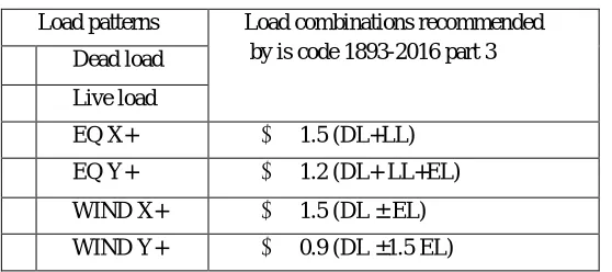
[image:2.612.169.448.586.710.2]c) Load Combinations: Load combination is the foremost important criteria for designing any structure and more important is the distribution of those loads on to various components of the structure like beams, columns, slabs and in our case shears walls and concrete core wall too. We have to consider the wind loads and places where rains are heavy rain loads are included and same way all the other loads such as snow loads, earthquake load and etc. Are included however dead loads, live loads and imposed loads are always included.
Table 2 load combinations
Load patterns Load combinations recommended by is code 1893-2016 part 3 Dead load
Live load
EQ X+ 1.5 (DL+LL)
EQ Y+ 1.2 (DL+ LL+EL)
WIND X+ 1.5 (DL ± EL)
613
©IJRASET: All Rights are Reserved
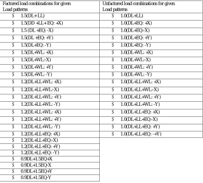
Table 3 Combinations for factored and unfactored loads. Factored load combinations for given
Load patterns
Unfactored load combinations for given Load patterns
1.5(DL+ LL) 1.0(DL+LL)
1.5(DD +LL+ EQ: +X) 1.0(DL+EQ: +X)
1.5 (DL +EQ: -X) 1.0(DL+EQ:-X)
1.5(DL +EQ: +Y) 1.0(DL+EQ: +Y)
1.5(DL+EQ: -Y) 1.0(DL+EQ: -Y)
1.5(DL+WL: +X) 1.0(DL+WL: +X)
1.5(DL+WL:-X) 1.0(DL+WL:-X)
1.5(DL+WL: +Y) 1.0(DL+WL: +Y)
1.5(DL+WL: -Y) 1.0(DL+WL: -Y)
1.2(DL+LL+WL: +X) 1.0(DL+LL+WL: +X)
1.2(DL+LL+WL:-X) 1.0(DL+LL+WL:-X)
1.2(DL+LL+WL: +Y) 1.0(DL+LL+WL: +Y)
1.2(DL+LL+WL: -Y) 1.0(DL+LL+WL: -Y)
1.2(DL+LL+WL: +X) 1.0(DL+LL+EQ: +X)
1.2(DL+LL+WL: +Y) 1.0(DL+LL+EQ:-X)
1.2(DL+LL+WL: -Y) 1.0(DL+LL+EQ: +Y)
1.2(DL+LL+EQ: +X) 1.0(DL+LL+EQ: -+Y)
1.2(DL+LL+EQ:-X)
1.2(DL+LL+EQ: +Y)
1.2(DL+LL+EQ: -Y)
0.9DL+1.5EQ+X
0.9DL+1.5EQ-X
0.9DL+1.5EQ+Y
0.9DL+1.5EQ-Y
IV.EXPERIMENTALPROGRAMME
A. Method of Analysis
Earthquake response analysis corresponds to simulate the behavior of a structure subjected to earthquake ground motion by means of a mathematical model of the structure. A three-dimensional model has independent displacements at each node and can simulate any type of behavior. The present study undertaken deals with Linear Static Method of Analysis or Equivalent Static Method of Analysis of 3D frames that can be used for regular structure with limited height.
B. Modeling of the Structure
For the present 3D study ETABS software package is used, where the floor Slabs are not discretized for analysis and the load is applied directly to the beams.
C. Details of Structure 1) Beam Cross-Sections
(Primary Beam) (Z x Y): 230mm X 450mm, 230mm X 530mm (Secondary Beam) (X x Y): 230mm X 380mm
2) Column Orientation and Cross-Sections
Three size / orientation of columns considered (such thatthe total area remains same) are as follows. Regular (X x Z): 230mm x 530mm
CL2 - Orientation change (X x Z): 230mm x 450mm 3) Shear Wall Thickness
614
©IJRASET: All Rights are Reserved
Table 4 - Material Properties
Name Type E
MPa ν
Unit Weight
kN/m³
Design Strengths
4000Psi Concrete 24855.58 0.2 23.5631 Fc=27.58 MPa
A416Gr270 Tendon 196500.6 0 76.9729 Fy=1689.91 MPa,
Fu=1861.58 MPa
A615Gr60 Rebar 199947.98 0.3 76.9729 Fy=413.69 MPa,
Fu=620.53 MPa
HYSD500 Rebar 200000 0 76.9729 Fy=500 MPa, Fu=545
MPa
M20 Concrete 22360.68 0.2 25 Fc=20 MPa
Table 5 - Frame Sections
Name Material Shape
B 230 X 380 M20 Concrete Rectangular B 230 X 450 M20 Concrete
Rectangular B 230 X 530 M20 Concrete
Rectangular C 230 X 380 M20 Concrete
Rectangular C 230 X 450 M20 Concrete
Rectangular C 230 X 530 M20 Concrete
Rectangular
a) Seismic Zone: The behavior of all the models with and without effect of shear wall is studied for all Zones of Seismic zones of India as per IS code (Ref. – 2) for which zone factor (Z) is given in code for different zone.
Table 6 - Shell Sections
Name
Design
Type
Element
Type
Material
Total
Thickness
mm
Slab150 Slab Shell-Thin M20 150
Wall1 Wall Shell-Thin 4000Psi 250
b) Load Consideration: The dead load consists of self-weight of structural elements and masonry wall load of thickness 230 mm. (The lateral load resistance effect of infill wall is not considered for analysis). The live load considered is as adopted for medium office, hospital or hostel building i.e.,4 KN/m2 as per IS code (Ref. – 3). The Equilibrium Static Method of analysis is adopted for the calculation of the lateral load at each floor level as per IS code (Ref. – 2). The lateral loads applied are given below.
V. RESULTS
Table 7 Research Module
Sr. No Description Abbreviations Base Shear in ‘KN’
With Shear Wall Without Shear Wall 1 G+24 Structure (Zone 2) Model 1 115.30 136.06
615
©IJRASET: All Rights are Reserved
Graph 1: - Base Shear (Story wise) with shear wall
Graph 2: - Base Shear (Story wise) without shear wall
VI.CONCLUSION
A. Base shear of structure is totally depending upon the entire lumped mass (inclusive Self weight and live load) of the structure. B. The lateral force response in case of shear wall is less effective than response of column to reduce the earthquake effect on
entire structure.
C. In case of without provision of shear wall base shear of severe (very high risk) zone is almost twice of the Low (very low risk) zone in case of column.
D. Provision of shear wall gives value of base shear of severe (very high risk) zone moderately less as compared to the Low (very low risk) zone.
E. For multi rise structure provision of shear wall is quite effective than provision of column in order to reduce the response of earthquake to the structure.
VII. FUTURESCOPE
A. To reduce the seismic effect in earthquake prone regions mainly.
B. In order to increase the serviceability of structure through the design life period it is important to provide such element which develops stability in earthquake prone areas ultimately.
616
©IJRASET: All Rights are Reserved
REFERENCES
[1] A. Jadhav, Dr. S. K. Kulkarni, A. A. Galatage, “Comparison Of The Effect Of Earthquake And Wind Loads On The Performance Of RC Framed Shear Wall Building With Its Different Orientation” (2016).
[2] Ravi Kumar, K. Sundar Kumar, “Analysis and Design of Shear Wall for an earthquake Resistant Building Using ETABS” (2017). [3] J.D. Chaitanya Kumar, Lute Venkat, “Effect of Lateral Forces on Precast Shear Wall” (2016).
[4] J Tarigan, J Manggala, T Sitorus, “The Effect Of Shear Wall Location In Resisting Earthquake” (2017).
[5] K.Sowjanya, Jarugulasrinivasulu, M.Mustaqahmmad, Et.Al, “Design And Analysis Of Educational Building Using ETABS”, (2018).
[6] Mahdi Hosseini, Dr.Hadi Hosseini, et.Al., “Effective Of Earthquake Load On Behavior Of Rectangular Shear Wall In RC Frame Building” (2015). [7] Narla Mohan, A.Mounika Vardhan, “Analysis Of G+20 RC Building In Different Zones Using ETABS”, (2017).
[8] S. V. Venkatesh, H. Sharada Bai (2011), “Effect Of Internal & External Shear Wall On Performance Of Building Frame Subjected To Lateral Load”, (2011). [9] S.Vijaya Bhaskar Reddy, Yugandhar Sagar.A, Srinivas Vasam, P,Srinivasa Rao, “Effect Of Wind Forces On Multistoried Structures”, (2015).