© 2018, IRJET | Impact Factor value: 6.171 | ISO 9001:2008 Certified Journal
| Page 1118
COMPARATIVE STUDY OF DIFFERENT TYPES OF BRACING AND
REGULAR RCC STRUCTURE
Dr. Ramakrishna Hegde
1, Ravi Kiran
2, Supriya
31
Head of Department, Department of Civil Engineering, Srinivas School of Engineering, Mangalore, India
2Assistant Professor, Department of Civil Engineering, Srinivas School of Engineering, Mangalore, India
3
M. Tech Student, Department of Civil Engineering, Srinivas School of Engineering, Mangalore, India
---***---Abstract –
Now a days, bracings are most popular system.It is the best method for lateral load resisting systems and it will be the viable solution for enhancing earthquake resistance. It is provides for minimizing the lateral deflection of buildings. In the present study G+15 storeys is analyzed for Z-III by considering soil type II. The analysis carried out to assess the structural performance under earthquake ground motions. In this study there are three different types of bracing i.e. X bracing, V bracing, and Diagonal forward bracing and without bracing by using same plan in both X & Y Directions. Results are obtained by considering Storey Displacement, Storey Shear, Storey Drift & Mode Period.
Key Words: Storey displacement, story drift, base shear,
time period, ETABS.
1. INTRODUCTION
Bracing is a structural member which can resist lateral loading. It is made up of Steel and RCC material which enables to resist lateral load. Bracing frames are classified in to X bracing, V bracing, Inverted V bracing, Diagonal forward bracing, Diagonal backward bracing. Bracings help to minimize the beam and column dimension. It also reduces the cost. Bracing of a building is done by two methods namely, concentric bracing and diagonal bracing. This both methods are done by the longer and shorter direction. The provision of bracings enhances stiffness and strength. Bracing which decreases the damage to the structure by decreasing the sway in lateral. Bracing which shows the good performance, if it is properly detailed and designed. Bracing which carries forces due to earthquake, overturning effect. In tall buildings there will be a chances of decrease in the displacement and collapsible chances due to more number of stories. Bracing are effective in minimizing the forces of quake and wind.
SCOPE OF STUDY
Buildings with same types of the zonal condition and for the same category can be adopted. Without bracing and with bracing i.e. X bracing, V bracing and Diagonal forward bracing can be adopted. It shows the behavior of the different bracings when it is placed at the same locations. Analysis of response such as storey displacement, storey shear, and time period is carried out using the ETABS 2015.
1.2 OBJECTIVE OF STUDY
The objective of this study is:-
a. Response spectrum analysis is carried out using ETABS2015 software
b. To determine the storey drift , storey displacement, time period and base shear
c. The concept behind the project is analysis of without bracing and with bracing i.e. X bracing, V bracing, Diagonal forward bracing of same plan.
2. NARRATIVE OF MODEL
The present work involves analysis of without bracing and with bracing i.e. X bracing, V bracing, Diagonal forward bracing of same plan. In this project, modeling and analysis are carried for G+15 stories modeling and analysis is done using ETABS-2015 software. There are four models. Model 1 consist a without bracing, model 2 consists an X bracing, Model 3 consists a V bracing and mode 4 consists a Diagonal forward bracing. The dimension of all models is of bay length 4m x 5m. Each model is done by ETABS.
2.1 BUILDING DESCRIPTIONS
a.
Material properties
Young’s modulus of (M25)
concrete 25*1000 kN/m
3
Density of reinforced concrete 25kN/m3
Young’s modulus of steel 2*105 kN/m2
Density of steel Fe415
Poisson’s ratio 0.2
b.
Details of building
Plan area dimension (4*5) m
No. of floors in two models G+15
© 2018, IRJET | Impact Factor value: 6.171 | ISO 9001:2008 Certified Journal
| Page 1119
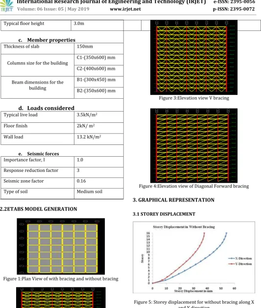
Typical floor height 3.0mc.
Member properties
Thickness of slab 150mm
Columns size for the building C1-(350x600) mm C2-(400x600) mm
Beam dimensions for the building
B1-(300x450) mm
B2-(350x600) mm
d.
Loads considered
Typical live load 3.5kN/m2
Floor finish 2kN/ m2
Wall load 13.2 kN/m2
e. Seismic forces
Importance factor, I 1.0
Response reduction factor 3
Seismic zone factor 0.16
Type of soil Medium soil
[image:2.595.37.571.53.681.2]2.2ETABS MODEL GENERATION
Figure 1:Plan View of with bracing and without bracing
Figure 2:Elevation View of X bracing
Figure 3:Elevation view V bracing
Figure 4:Elevation view of Diagonal Forward bracing
3. GRAPHICAL REPRESENTATION
[image:2.595.308.561.499.651.2]3.1 STOREY DISPLACEMENT
© 2018, IRJET | Impact Factor value: 6.171 | ISO 9001:2008 Certified Journal
| Page 1120
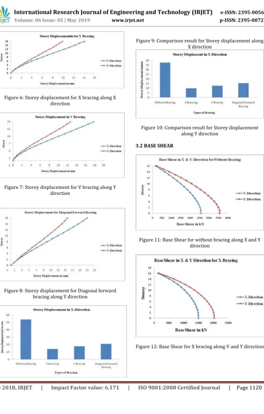
Figure 6: Storey displacement for X bracing along X [image:3.595.44.559.32.838.2]direction
Figure 7: Storey displacement for V bracing along Y direction
Figure 8: Storey displacement for Diagonal forward bracing along Y direction
Figure 9: Comparison result for Storey displacement along X direction
Figure 10: Comparison result for Storey displacement along Y direction
3.2 BASE SHEAR
Figure 11: Base Shear for without bracing along X and Y direction
© 2018, IRJET | Impact Factor value: 6.171 | ISO 9001:2008 Certified Journal
| Page 1121
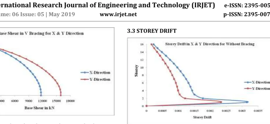
Figure 13: Base Shear for V bracing along V and Y directionFigure 14: Base Shear for Diagonal forward bracing along V and Y direction
Figure 15: Variation of Base Shear along X direction
Figure 16: Variation of Base Shear along Y direction
[image:4.595.92.552.47.258.2]3.3 STOREY DRIFT
Figure 17: Storey drift for without bracing along X and Y direction
Figure 18: Storey drift for X bracing along X and Y direction
[image:4.595.36.282.279.410.2]© 2018, IRJET | Impact Factor value: 6.171 | ISO 9001:2008 Certified Journal
| Page 1122
Figure 20: Storey drift for Diagonal Forward bracing along [image:5.595.38.290.434.549.2]X and Y direction
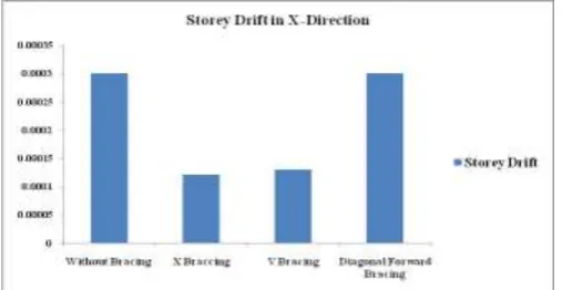
Figure 21: Variation of Storey Drift along X direction
Figure 22: Variation of Storey Drift along Y direction
3.4 TIME PERIOD (MODE PERIOD)
Figure 23: Variation of Time period for without bracing and different types of bracing
4. RESULT AND DISCUSSIONS
1. Storey displacements: From the obtained results it is found that for X and Y directions the displacement reduced when compared to without bracing model. The displacements at 16th storey in X direction for reduces by X bracing, V bracing, diagonal forward bracing are 14.1mm, 17.8mm, 21mm respectively and Y direction 9.9mm, 12.7mm, 15.6mm.
2. Base shear: From the obtained results it is found that for X and Y directions the base shear increased when compared to without bracing model. The base shear for 16 storey in X direction for reduces by X bracing, V bracing, diagonal forward bracing are 1300.32kN, 1035.6kN, 871.8kN respectively and Y direction 1649.8kN, 1372.7kN, 1067.4kN.
3.
Storey drift: Storey drift obtained results it is found that for X and Y directions the storey drift increased when compared to without bracing model. The storey drift at 16th storey in X direction for reduces by X bracing, V bracing, diagonal forward bracing, are 0.0003, 0.0004, 0.0004 respectively and Y direction 0.0002, 0.0003, 0.0003.4. Time period: Time period in without and with bracing i.e. X-Bracing, V-Bracing, Diagonal Forward Bracing time period are 4.04sec, 0.76sec, 0.95sec and 0.10Sec. There are decreases in natural period for different types of Bracing compared to without bracing.
4.1 CONCLUSIONS
Storey Displacement Values along both directions for without bracing gradually increases. It is observed that storey displacement value for without bracing is more compare to the X Bracing, V Bracing and Diagonal Forward Bracing. Reduction in displacement which provides rigidity for the buildings.
Storey Shear increases for the bracing models especially for the X Bracing compared to Diagonal Forward Bracing, V Bracing & without Bracing.4.2 FUTURE SCOPE
In this study symmetric plan is selected and further study can be carried out for asymmetric plan.
Studies can carried out for providing different types of bracing such as Inverted V Bracing, Diagonal Backward Bracing.
REFERENCES
© 2018, IRJET | Impact Factor value: 6.171 | ISO 9001:2008 Certified Journal
| Page 1123
[2] Ashik S, Parasiyal Paresh Nimodiya “A ComparativeStudy of Wind Forces on tall building and towers as per IS 875-PART-III (1987) and draft code (2011) using gust factor method”, National Conference on wind Engineering 2012, Dec. 14-15.
[3] Kulakarni J.G., Kore P.N., Tanawade S.B., “Seismic Response of RC Braced Frames”, International Journal of Engineering Research and Applications”, Vol.3 (4), 2013, ISSN 2248-9622,pp. 1047-1053.
[4] Nicka.Keipour, and Elyar.Zafarkhah, and Masood.Mofid. “Influence of Diagonal Braces in RCC Multi-storied frames under wind loads: a case study”, International Journal of Civil and Structural Engineering, Vol.3 (1), 2012.
[5] Nithin Bhojkar, and Mahesh Bhagade “Behaviour of Multi-storied building under the effect of wind load”, International Journal of Applied Sciences and Engineering Research, Vol.1, 2012 , Issue 4.
[6] Patil S.S., Aland S.S., Kore P.N., “Seismic Response of Concentrically Braced Reinforced Concrete Frames”. International Journal of Scientific and Engineering Research, Vol.4 (7), 2013, ISSN 2229-5518.
[7] P. Sairaj, K.Padmanabham “Performance base Seismic design of Braced Composite Multi-storied building” International Journal of Innovative Research in Science, Engineering & Technology (An ISO 3297:2007 Certified Organization) Vol.3, 2014,Issue2. (7).
[8] Y.U. Kulakarni and Prof. P.K. Joshi “Analysis and Design of Various Bracing System in High Rise Steel Structure” International Journal of Advance Research in Science and Engineering IJARSE, Vol. No.3, 2014, Issue No.3, Issue No.11, ISSN-2319-8354(E).
[9] Zasiah Tafheem, Shovona Khusuru “Structural Behaviour of Steel Building with Concentric and Eccentric Bracing, A Comparative Study”, International Journal of Civil and Structural Engineering Vol.4 (7),2013.
[10] IS: 1893(Part-1)-2002 Indian Standard Criteria Earthquake Resistant Design Of Structures, Bureau Of Indian Standards New Delhi.