Enhance Virtual-Machine-Based Code Obfuscation Security
Through Dynamic Bytecode Scheduling
1Kaiyuan Kuanga, Zhanyong Tanga,, Xiaoqing Gonga, Dingyi Fanga, Xiaojiang Chena, Zheng Wangb,
aSchool of Information Science and Technology, Northwest University, China.
bSchool of Computing and Communications, Lancaster University, UK
Abstract
Code virtualization builds upon virtual machine (VM) technologies is emerging as a viable method for implementing code obfuscation to protect programs against unauthorized analy-sis. State-of-the-art VM-based protection approaches use a fixed scheduling structure where the program always follows a single, deterministic execution path for the same input. Such approaches, however, are vulnerable in certain scenarios where the attacker can reuse knowl-edge extracted from previously seen software to crack applications protected with the same obfuscation scheme. This paper presents Dsvmp, a novel VM-based code obfuscation
ap-proach for software protection. Dsvmp brings together two techniques to provide stronger
code protection than prior VM-based approaches. Firstly, it uses a dynamic instruction scheduler to randomly direct the program to execute different paths without violating the correctness across different runs. By randomly choosing the program execution path, the application exposes diverse behavior, making it much more difficult for an attacker to reuse the knowledge collected from previous runs or similar applications to launch an attack. Secondly, it employs multiple VMs to further obfuscate the mapping from VM opcode to native machine instructions, so that the same opcode could be mapped to different native instructions at runtime, making code analysis even harder. We have implementedDsvmp in
a prototype system and evaluated it using a set of widely used applications. Experimental results show that Dsvmp provides stronger protection with comparable runtime overhead
and code size, when it is compared to two commercial VM-based code obfuscation tools.
Keywords: Code virtualization, Code Obfuscation, Reverse Engineering
1Extension of Conference Paper: a preliminary version of this article entitled “Exploiting Dynamic
1. Introduction
Unauthorized code analysis and modification based on reverse engineering is a major concern for the software industry. Such attacks can lead to a number of undesired out-comes, including cheating in online games, unauthorized use of software, pirated pay-tv etc. Industry is looking for solutions for this issue to deter reverse engineering of software systems. By making sensitive code difficult to be traced or analyzed, code obfuscation is a potential solution for the problem.
Code virtualization based on a virtual machine (VM) is emerging as a promising way for implementing code obfuscation [2, 3, 4, 5, 6, 7, 8]. The underlying principal of VM-based protection is to replace the program instructions with virtual instructions which attackers are unfamiliar with. These virtual instructions will then be translated into native machine code at runtime to be executed on the underlying hardware platform. Using a VM-based scheme, the execution path of the obfuscated code is controlled by a virtual instruction scheduler. A typical scheduler consists of two components: a dispatcher that determines which instruction is ready for execution, and a set ofbytecode handlers that first decode the bytecode2 and then translate it into native machine code. This process replaces the original program instructions with bespoke bytecode, allowing developers to conceal the purpose or logic of sensitive code regions.
Prior work on VM-based software protection primarily focuses on making a single set of bytecodes more complicate, and uses one single virtual instruction scheduler. This is based on the assumption that the scheduler and the bytecode instruction set are difficult to be analyzed in most practical runtime environments. However, research has shown that this is an unreliable assumption [9] in certain scenarios where an adversary can easily reuse knowledge obtained from other applications protected with the same scheme to preform reverse engineering (termed cumulative attacks in this work). To protect software against cumulative attacks, it is important to have a certain degree of non-determinism and diversity during program execution [10].
This paper presentsDsvmp (dynamic scheduling for VM-based code protection), a novel
VM-based code protection scheme to address the problem of cumulative attacks. Our key insight is that it will be more difficult for the attacker to track the application logic if sen-sitive code regions behave differently in different runs. Dsvmp achieves this by introducing
rich non-determinism and diversity to program execution. To do so, it exploits a flexible, multi-dispatched scheme for code scheduling and interpretation. Unlike prior work where a program always follows a single, fixed execution path for the same input across different runs, theDsvmpscheduler directs the program to execute a randomly selected path for each
Email addresses: [email protected](Kaiyuan Kuang),[email protected](Zhanyong Tang),
[email protected](Xiaoqing Gong),[email protected](Dingyi Fang),[email protected](Xiaojiang Chen),[email protected](Zheng Wang)
protected code region. As a result, the program follows different execution paths in different runs and exposes an non-deterministic behavior. Our carefully designed scheme ensures that the program will produces a consistent output for the same input despite the execution paths might look differently from the attacker’s perspective. To analyze software protected underDsvmp, the adversary is forced to use a large number of trail runs to understand the
logic of the program. This significantly increases the cost of code reverse-engineering. Dynamic instruction scheduling in Dsvmp is achieved through a combination of two
techniques. Firstly, Dsvmp provides a rich set of bytecode handlers, each of which has a
unique control flow, to translate a bytecode instruction to native code. Handlers for a partic-ular bytecode opcode all generate identical native machine instructions for the same input, but their execution paths and data accessing patterns are different from each other. During runtime, our VM instruction scheduler randomly selects a bytecode handler to translate a bytecode to the corresponding native machine code. Since the choice of handlers is random-ly determined at runtime for each bytecode instruction and the implementation of different handlers are different, the dynamic program execution path is likely to be different across different executions. Secondly, Dsvmp employs a multi-VM scheme so that various code
regions can be protected using different bytecode instruction sets and VM implementations. This further increases the diversity of the program, making it even harder for an adversary to analyze the software behavior or to reuse knowledge extracted from other software prod-ucts. This is because different products are likely to be protected using different bytecode forms and VM implementations.
The whole is greater than the sum of the parts. These techniques, putting together, enableDsvmpto provide stronger code protection than any of the VM-based techniques seen
so far. We have evaluatedDsvmp on four applications that implement some of the widely
used algorithms: “md5”, “aescrypt”, “bcrypt” and “gzip”. Experimental results show that Dsvmp provides stronger protection with comparable runtime overhead and code size
when compared to two commercial VM-based code obfuscation tools: Code Virtualizer [3] and VMProtect [4].
This paper makes the following contributions:
• It presents a dynamic scheduling structure for VM-based code obfuscation to protect software against dynamic cumulative attacks.
• It is the first to apply multiple VMs to enhance diversity of code obfuscation.
• It demonstrates that the proposed scheme is effective in protecting real-world software applications.
The rest of this paper is organized as follows. Section 2 introduces the principle of classical VM-based code obfuscation techniques and cumulative attacks scenario. Section3
describes the VM reverse attacking approach. Section4gives an overview of Dsvmp, which
Target Program
Key code
push ebx add ecx, eax
Native instr. loadd r3
loadd r1 loadd r0 addd stored r1
01 03 02 01 02 00 1b 03 01
Virtual instr. Bytecodes
VM Section jmp VMinit
Junk Instr
Out Program
VM Section
VMcontext VMinit Dispatcher
Handlers Bytecode
Program VMexit 1 Key code extraction 2 Virtualization 3 Bytecodes 4 File refactoring
[image:4.595.93.502.113.230.2]generation
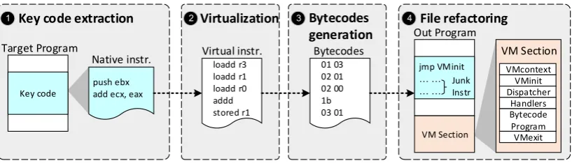
Figure 1: A classical process for VM-based code obfuscation. To obfuscate the code, we first dissemble the code region to be protected into native assembly code (1). The assembly code will be mapped into our virtual instructions (2) which will then be encoded into a bytecode format (3). Finally, the generated byecode will be inserted into a specific region of the binary which is linked with a VM library (4).
2. Background
2.1. VM-based Code Obfuscation
VM-based code obfuscation often performs at the binary level for an already compiled program. As shown in Figure1, the obfuscation process typically follows a number of steps. Firstly, the critical code segment to be protected will be extracted from the compiled binary, which will be dissembled into assembly code. Next, the native assembly code will translated into virtual instructions, i.e. a machine-independent intermediate representation used by our VMs. The translated virtual instructions are functional equivalent to original native code. Then, the generated virtual instructions will be encoded into the bespoke bytecode format. Finally, a new VM section will be linked (or inserted) into the target program where the entry point of the protected code region will be redirected to a function call to invoke the VM to translate the bytecode instructions to native machine code at runtime.
The idea of VM-based code obfuscation is to force the attacker to move from a familiar instruction set (e.g. x86) to an unfamiliar bespoke virtual instruction set, which hopefully will significantly increase the time and efforts for reverse-engineering.
2.2. VM Components.
Our approach follows a classic VM implementation, consisting of a number of components that are shown in step 4 at Figure 1. The context of the native program, which includes information such as local variables, function arguments, the return address etc., will be stored in a register-based VM memory space calledVMContext. When entering the VM, the
VMinit component saves the native program context and initializes the VMContext. After executing the protected code segment, VMExit restores the native program context, and then returns the program control back to the original program to continue executing native machine code.
Number of attacks P1
P2
P
P1 P2
Protect by Our approach
attcker
Eventually compromise the target software
After a lot of attempts, failure and give up
Succeed
[image:5.595.148.440.111.251.2]Failure
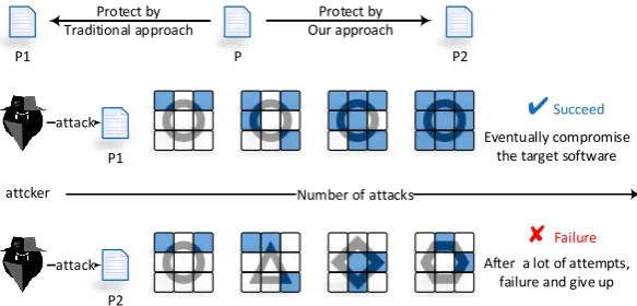
Figure 2: Diversity affects the attack effectiveness. In this example, a dark small square represents reusable attacking knowledge. Diverse program execution increases the difficulty for performing reverse-engineering based attacks.
(from a collection of handlers that can be used to interpret the bytecode) to translate the fetched bytecode to native machine code. This process iterates until all the bytecode of the target protected code region are executed. For the attacker’s perspective, the key to understand the logic of the protected code region is to find out how bytecode or virtual instructions are mapped into native machine code.
2.3. The Design Goal
Figure2 gives a high-level abstraction on how an attacker can reuse knowledge extract-ed from the previous runs of the same application or other applications protectextract-ed under the same VM scheme to perform reverse-engineering. This kind of attacks is referred as
cumulative attacks in this paper.
In the first scenario, the software always follows the same execution path across multiple runs. Under this setting, the attacker may be able to obtain sufficient knowledge on the program behavior in a few trail runs. In the second scenario, the program execution path changes across different runs. As such, it will take longer and many more runs to gather enough information to perform the attack. As can be seen from this simple illustration, diversity is key for us to protect software against dynamic cumulative attacks. This is the aim of this work, to improve the diversity of program executions for code obfuscation. It is to note that like any other code protection techniques, our approach could also be exploited by malware. How to prevent this is out of the scope of this work.
3. The Attack Model
3.1. Attacking methods
semantics of the bytecode instructions, i.e. how will a bytecode opcode be translated into a native machine instruction. The third step is to use knowledge obtained in the first two steps to recover the logic of the target code region, through e.g. removing the redundant information and generating a simplified program that is equivalent to the original program. To perform such an attack, a significant portion of the time will have to spend in analyzing the working mechanism of the VM. The problem is that a skilled attacker could reuse knowledge gathered from parts of the program to analyze other protected code regions of the same program, or other applications protected using the same VM scheme and bytecode instructions.
3.2. The Threat model
Our attack model assumes that the attacker has the necessary tools and skills to imple-ment the above reverse-engineering based attacks. We assume that the adversary holds an executable binary of the target software and can run the program in a control environmen-t [12]. We also assume that the adversary can access content stored in memory and registers, trace and modify program instructions and control flows. All these can be achieved using sophisticate profiling and analysis tools like “IDA” [13], “Ollydbg” [14] and “Sysinternals suite” [15]. The aim of the adversary is to completely reverse the internal implementation of the target program. Our goal is to increase the difficulties in terms of time and efforts for an adversary to reverse the target program implementation protected using VM-based code obfuscation.
4. Overview of Our Approach
To address the problem of cumulative attacks, we want to introduce a certain degree of diversity and non-determinism to the program execution. This is achieved through using a diversified scheduling structure (Section 5) and multiple VMs (Section 6). Like any VM-based protection schemes, Dsvmp should be used to protect the most critical code regions
but not the entire program, in order to minimize the runtime overhead. Our current imple-mentation targets the Intel x86 instruction set but the methodology itself can be applied to other instruction sets and hardware architectures. Figure3 depicts the system architecture of Dsvmp. Code protection of Dsvmp follows several steps described as follows.
Code translation. Dsvmp takes in a compiled program binary. It does not require having
Key code segment
Native Instr.
Multiple VMs
Junk Intr.
VM section
DSVMP
Target Program
Protected Program
Initial handlers
set
1
2
VMcontext Multiple
dispatchers
VMInit
VMExit VM
Components Multiple
sets of handlers
Multiple sets of bytecodes
Deformation engine
Serial number transformation
Virtual Instr.
4
6
7 6
3
5
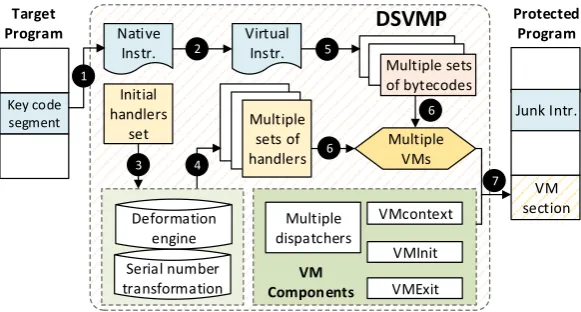
Figure 3: Offline code protection process. Dsvmp takes in a program binary. For each protected code region, it translates native instructions into bytecodes. Next, it generates multiple bytecode handlers that are semantically equivalent but implemented in different ways. It then generates the corresponding driver-data and multiple VMs. Finally, the generated VMs and associated components will be inserted into the program binary and fills the original code region with junk instructions.
Diversifying. As a departure from prior work on VM-based code obfuscation, Dsvmp em-ploys multiple VM instruction scheduling policies. Each virtual instruction scheduler can have multiple dispatchers and bytecode handlers. Dsvmpprovides a set of handlers that are
semantically equivalent but are implemented in different ways for a single virtual instruction. Thus, the scheduler can dynamically determine at runtime which of the handlers is used to decode a bytecode (i.e. the encoding scheme of the virtual instruction which includes the opcode and operand) and to interpret a virtual instruction. Multiple handlers are generat-ed by applying obfuscation to a set of segenerat-ed handlers (Step ¸). The way the handlers are obfuscated could be different for different code regions. Dsvmp also employs a multi-VM
scheme by providing more than one VM implementation. Therefore, each handler will be obfuscated for each VM by using the deformation engine (i.e. a obfuscation toolkit), result-ing in n (i.e. the number of VMs) sets of semantically equivalent handlers with different implementations and control flows (Step ¹). Next, the virtual instructions will be encoded into an unique bytecode form for each VM, so that the same opcode from different VMs will be mapped into different native machine instructions to protect against static analysis. Our preliminary implementation provides two sets of bytecode in a VM. Therefore, each virtual instruction can be encoded into two different sets of bytecode forms in a VM(Stepº). After these steps, Dsvmp essentially provides multiple VMs, where each VM contains one set of
bytecode handlers (so that a virtual instruction can be interpreted by multiple handlers), while the instructions of the protected code regions are stored in different bytecode forms (Step »).
[image:7.595.150.441.111.267.2]Main Function Control unit Directly dispatch the next Handler
Randomly return to a Dispatcher
lods byte ptr ds:[esi] xor al,bl
sub al,0xFA sub al,0x45 add bl,0x1 add esi,eax mov ebx,0
push eax rdtsc mov ecx,2 div ecx cmp edx,0 jz label
[image:8.595.98.510.114.234.2]lods byte ptr ds:[esi] ... ...
add eax,edx
jmp dword ptr ds:[edi+0x60+eax*4]
label: push ebx div bl movzx eax,AH add eax,9dH
jmp dword ptr ds:[edi+0x50+eax*4]
Handler
Next Handler
Dispatcher
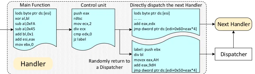
Figure 4: The execution flow of the new handler, each bytecode handler has a control unit that randomly determines whether the control after exiting the handler should be given to a dispatcher or an alternative bytecode handler.
byte) [16], we simply fills the original code region with junk instructions(Step ¼), rather than utilizing the space to store the VM code.
5. Dsvmp Scheduling Structure
The Dsvmp VM scheduler uses multiple dispatchers to determine which bytecode
in-struction should be interpreted at given time. A unique design of Dsvmp is that the dispatcher used to schedule bytecode handlers is dynamically changed at execution time. To further increase the diversity of the program’s behaviour, Dsvmp also uses multiple
bytecode instruction sets and bytecode handlers.
5.1. Multiple Bytecode Handlers
In classical VM-based code obfuscation, a single dispatcher is responsible for fetching a bytecode instruction, and then determining which bytecode handler to use by examining the opcode of the bytecode instruction. Because each bytecode instruction is decoded by a fixed handler set, an adversary can easily work out the mapping from an opcode to its handler. From the mapping, the adversary can correlate the native machine code to each bytecode to analyze the program behavior and the logic structure.
To address this issue, for each bytecode handler, we use obfuscation techniques to auto-matically generate a number of alternative implementations which all produce an equivalent output for the same input instruction. Different implementations, however, are programmed in different ways using e.g. different control flows, data structures or obfuscation methods.
To control the program execution path, we insert a control unit at the end of each bytecode handler. Before exiting a bytecode handler, the control unit randomly determines whether the control should be given back to a dispatcher or another handler. Figure4shows an example of the control unit of a Dsvmp bytecode handler. When the main function of
Dispatcher1 Dispatcher2 Dispatcher3
Handler 1
Handler 2
Handler 3
Handler 20
Handler 21
Handler 43
Handler n
Dispatcher1 Dispatcher2 Dispatcher3
Handler 1
Handler 2
Handler 3
Handler 20
Handler 21
Handler 43
Handler n
[image:9.595.151.449.112.269.2]
Standard Bytecode:02 XX 01 21 XX 43 20 ... Offset Bytecode:02 XX 93 20 XX 22 71 ...
Figure 5: Our approach employes multiple dispatchers together with a control unit to schedule the handlers. In this example, the type of handlers and the order for invoking the handlers could be different across execution runs. The “XX” in bytecode refers to the parameters. Underlined two bytecodes is handler43 encoding results in two types ofBytecode respectively
then jump to execute it. By contrast, the instruction at another branch will return to a dispatcher. Figure5 shows two different dynamic scheduling results. Under the instruction of the control unit, a handler can either be invoked by a dispatcher or a handler. TheOffset Bytecode here is different from the usual standard bytecode, which is designed to drive the handler’s dispatch function, and we will describe it in detail in the next section.
5.2. Multiple Bytecode Formats and Dispatchers
Bytecode Formats. Using VM-based obfuscation, native machine code of the protected code regions will be translated into virtual instructions and stored in a bytcode format. A handler will be chosen to decode the bytecode instruction to translate it back to native machine code at runtime. In classical VM-based code obfuscation approaches, there is one-one mapping from a bytecode opcode to a handler, i.e. the bytecode opcode determines which handler to be used. Having multiple bytecode instruction sets for different code regions of a target program can provide stronger protection. By doing so, the same opcode from different code region will have different semantic meanings. This is because the same opcode from different regions can be mapped to different handlers (and hence different native machine code implementations). For this reason, the virtual instructions of different code regions will be stored in different bytecode formats.
Our current implementation uses two bytecode formats for each VM, namely Standard Bytecode and Offset Bytecode. Additional bytecode formats can be easily added to our system. Here,Standard Bytecode is a standard bytecode format where each bytecode consists of the virtual instruction’s opcode3 and their operands. Instructions encoded as Standard
Bytecode will be fetched and executed by the dispatcher. Offset Bytecode uses a different encoding scheme, which is fetched by the handler’s control unit. Each Offset Bytecode
consists of the offset IDs of two handlers (e.g. handler21 and handler43 in Figure 5 has an offset ID of 22) and their operands respectively. Recall that a control unit is inserted to the end of each handler to determine whether the control should be given back to the dispatcher or another handler. Before exiting the current handler, if the control unit chooses to execute the next handler, it will fetch the corresponding offset ID from Offset Bytecode. The offset ID will then be used to calculate the id of the next handler to execute.
Dispatchers. Dsvmp also provides multiple dispatchers to further increase the diversity of
program execution. As an example, considering Figure5which shows two possible program execution paths using three dispatchers within a single VM. As can be seen from the dia-gram, each time when a different dispatcher is chosen, a handler can either be invoked by a dispatcher or another handler; and the type of handlers to be invoked could be different in two different execution runs. As a result, knowledge about the program control flow extracted from the first run does not apply to the second one.
6. Multiple VMs
In contrast to classical VM-based obfuscation approaches that uses a single VM (termed SVM),Dsvmp uses multiple VMs. Multiple VMs offer different sets handlers and bytecode instruction sets. Under such settings, bytecode instructions can be scheduled from different VMs and a virtual instruction can be interpreted by more than one handler. Therefore, there will be more than one possible mapping from a bytecode instruction to a handler. Together with the multiple scheduling approach described above, Dsvmp can further increase the
diversity and uncertainly of program execution.
6.1. Switching between Multiple VMs
The number of VMs to use is a parameter provided by Dsvmp. This can be configured
by the user. This number can vary depending on the target program to be protected, and the trade-off between the protection strength and runtime overhead. As described in Section 5.2, we generate a set of handlers for each VM so that we have n different sets of handlers for n VMs. Our current implementation also translates the virtual instructions of each handler set to stored as two different sets of bytecode. Different bytecodes will have different semantics in different VMs. Therefore, there are more than a bytecode that can be translated by different handlers in different VMs.
1 push edx ;−−−−−−−−−−−−−−−−−−−−−−−−
2 r d t s c
3 x o r edx,edx
4 d i v dword p t r ds: [e d i+0x58 ] ;VM s w i t c h i n g u n i t 5 mov eax,edx
6 sub edx,dword p t r ds: [e d i+0x50 ]
7 j e l a b e l ;−−−−−−−−−−−−−−−−−−−−−−−−
8 i m u l edx,dword p t r ds: [e d i+0x54 ] ; Modify t h e VM PC and 9 add e s i ,edx ; s a v e t h e c u r r e n t VM ID 10 mov dword p t r ds: [e d i+0x50 ] ,eax
11 l a b e l: l o d s b y t e p t r ds: [e s i] ;−−−−−−−−−−−−−−−−−−−−−−−−
12 . . . ; Fetch t h e b y t e c o d e and
13 movzx eax,a l ; d i s p a t c h a H a n d l e r
14 add eax,edx ; t o i n t e r p r e t i t
15 pop edx
[image:11.595.58.532.114.311.2]16 jmp dword p t r ds: [e d i+eax∗4+0 x60 ]
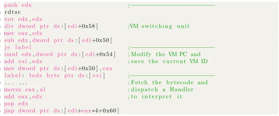
Figure 6: The new dispatcher has a VM switch unit that can randomly select one of the multiple VMs to continue scheduling handler.
VM (lines 11-16). The VM, the set of bytecode handlers and bytecode instructions will be randomly switched across different code regions in both a single execution and across different program runs.
6.2. The VM Scheduling Process
Our dynamic scheduling is achieved through two control units: (1) a structure control unit to randomly determine whether the execution control should be given to a dispatcher or another bytecode handler, (2) a VM switching unit to randomly select a VM to use. Having these two control units to switch the execution path of virtual instruction interpretation can greatly increase the diversity of the program behavior when compared to existing approaches that have a single, fixed scheduling structure.
Our dynamic scheduling scheme is described in Algorithm1. Bytecodes of a code region will be executed one after one in sequential order. The virtual interpreter fetchs a bytecode fromStandard Bytecode and dispatchs a handler to interpret the bytecode (lines 5-6). After executing the bytecode, the control unit will randomly decide whether the control should be given back to a bytecode dispatcher or a VM handler (line 7). If the control is given back to a bytecode dispatcher (lines 8-11), a dispatcher and a VM will be randomly chosen to execute a bytecode from Standard Bytecode. If the control is directed to another bytecode handler (lines 12-13), the program will execute the next bytecode from Offset Bytecode . The process continues until all the virtual instructions of the protected code region have been executed.
7. An Example
We use a short x86 code snippet shown in Figure 7 as an example to illustrate how
Algorithm 1Virtual Interpreter’s Work Flow 1: VMInit
2: Switcher selects a VM randomly
3: Fetch a bytecode from Standard Bytecode in current VM 4: while bytecode6=∅ do
5: Decode the bytecode
6: Select a handler to interpreter the bytecode 7: i = handler exit address
8: if i == dispatcher then 9: Select a dispatcher randomly
10: Switching unit selects a VM randomly
11: Fetch the next bytecode fromStandard Bytecode from the selected VM 12: else {i == handler}
13: Fetch the next bytecode fromOffset Bytecode in the current VM
14: end if
15: end while
16: VMExit
1 STARTSDK
2 0 0 4 0 10 3 6 mov eax, ebx 3 0 0 4 0 10 3 8 sub eax, 03 4 ENDSDK
Figure 7: Example assembly code snippet for a code region to be protected.
and end of the code region respectively, and “00401036” and “00401038” are the address of two assembly instructions.
7.1. Code obfuscation
Table 1 shows the resulted obfuscated code for the code example given in Figure 7. Firstly, Dsvmp extracts the target code region and disassemble it into native instructions. Dsvmp inserts two additional instructions (“push 0x40103b” and “ret”) at the end of the protected code region, in order to jump back to execute the native code. It then converts the native instructions to virtual instructions based on a translation convention. Dsvmp’s
bytecode instructions are based on a stack machine model. Here the load instruction is used to push operands into the stack, and the store instruction is used to pop results out from the stack and store the result to the virtual context (VMContext).
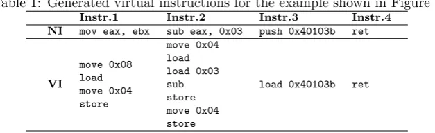
Table 1: Generated virtual instructions for the example shown in Figure7
Instr.1 Instr.2 Instr.3 Instr.4
NI mov eax, ebx sub eax, 0x03 push 0x40103b ret
VI
move 0x08 load move 0x04 store
move 0x04 load load 0x03 sub store move 0x04 store
load 0x40103b ret
Notes: In the table, “NI” indicates the native x86 instructions, and “VI” donates the virtual instructions. Here, our system inserts “Instr.3” and “Instr.4” in order to jump back to execute the native code after returning from the protected code region.
(Set11) and Offset Bytecode (Set12) for HSA1 and Standard Bytecode (Set21) and Offset Bytecode (Set22) for HSA2. The resulted program is illustrated in Figure 8. We store the virtual instructions as bytecode. Because the resulted code size is larger than the original code and hence cannot simply be used to replace the original instructions. For this reason, we simply fill the original code region with junk instructions.
Finally, Dsvmp creates a new code section attached to the end of the target program.
The new code section contains the implementation of the handlers, different sets of bytecode instructions, dispatchers and other VM components such VMContext and routines such as
VMInit(used to initialize the VM) andVMExit(use for cleaning up the context before exiting the VM).
7.2. Runtime execution
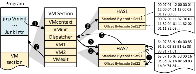
Runtime execution of the protected code region is illustrated in Figure 8, which follows a number of steps:
• Step 1: The entry of the protected code segment contains an “jmp VMInit” instruc-tion. This transfers the control to the VM initialization routine, VMInit, which saves the native host context and initializes the virtual context,VMContext.
• Step 2: Next, a dispatcher is used to schedule the virtual instructions. It randomly selects a VM (the example shown in Figure8assumes thatVM2is chosen at beginning) and then it fetches a bytecode from the Standard Bytecode, Set21. After decoding the bytcoe, the dispatcher gets an operand, “6a”, which directs the dispatch to jump to execute another handler, “0x6aHandler”.
• Step 3: A control unit is executed (see Section5.1) before exiting the “0x6aHandler” handler. The control unit determines at runtime whether to execute another handler or to return the control to the dispatcher. If it chooses to return the control to the dispatcher, the program execution moves to Step 5.
6a 07 85 91 6a 00 85 91 6a 02 85 91 6a 03 85 91 71 01 ... jmp Vminit
Junk Intr
VM Section VMcontext
VMinit Dispatcher
VM1 VM2 VMexit
HAS1 Standard Bytecode Set11
Offset Bytecode Set12
HAS2 Standard Bytecode Set21
Offset Bytecode Set22 VM
section
00 07 01 12 00 00 01 12 00 04 01 12 00 02 01 12 00 03 ... 00 07 01 11 82 0 0 01 11 82 04 01 11 82 02 01 11 82 03 ...
6a 07 1b 0c 6d 00 1b 0c 6d 02 1b 0c 6d 03 1b 0c 74 24 ...
1
7
2 3
4 5
6
[image:14.595.127.471.110.241.2]Program
Figure 8: The execution process of the protected program. Here each VM has two sets of bytecode instruc-tions and one set of handlers.
control unit will then jump to execute “0x85Handler”. After executing this handler, the program execution loops back to Step 3.
• Step 5: If the control unit chooses to return the control to a dispatcher, it will randomly select a dispatcher to continue the execution. Then, the program moves to Step 6.
• Step 6: The selected dispatcher randomly selects one of the VMs to use. The dispatch-er fetches a bytecode from the selected VM, decoding it to get the handldispatch-er’s address. It then jumps to execute the handler. After executing the handler, the program goes back to Step 3.
• Step 7: Steps 3 and 4 are iterated until all the virtual instructions get executed. The finally step is to invoke theVMExit procedure to restore the native execution context to continue executing the rest native code of the program.
8. Security Strength Analysis
In this section, we evaluate the security strength of Dsvmp. We first analyze the number
of possible execution paths, showing that Dsvmp can significantly increase the diversity
and non-determinism of program execution. Then, we discuss howDsvmp can enhance the
diversity of code structures.
8.1. Program execution paths
Recall that our design goal is to increase the diversity of program execution, so that in different runs the protected region does not follow a single execution path across runs. To make the analysis concrete, we assume that there are 10 different dispatchers, which is the standard setting in the current implementation of Dsvmp. We use the example presented in
where each handler can lead to 11 different execution paths. This is because at the end of executing each handler, a control unit will determine whether the control should be given to another handler or one of the 10 dispatchers (see Section5.1) – 11 possibilities in total.
In combination, these options give 1177 possible execution paths for each protected code
region. Therefore, the probability,p, for a protected code region to follow the same execution path across different runs is p = 1
1177, a small possibility. It is to note that so far we have
assumed that the protection scheme uses just one VM. The multi-VM strategy employed byDsvmp can further increase the number of possible execution paths. This is because the
more dispatchers and VMs are, the greater number of possible execution paths will be. For example, if the Dsvmp implementation provides five different VMs, then each dispatcher
can randomly select one VM among the 5 VMs; as a result, each handler can lead to 51 (= 10∗5 + 1) different execution paths. Together with multiple dispatchers and bytecode instruction strategies, for the setting used in this discussion, Dsvmp gives a single code
region 5177 possible execution paths.
In summary, we can conclude that for a single code region protected by Dsvmp, its
possible execution path number,m, and the probability of its execution of the same execution path across different runs, p, respectively are:
m = (ND ∗NV M + 1)n, p= 1/m.
where ND represents the number of dispatcher, NV M is the number of VMs, and n is
the number of handler scheduling options. Given the massive number of choices, it will be unlikely for a protected code region to follow the same execution path across different runs.
8.2. Code structures
Having a diverse code structure is key to prevent an adversary from reusing knowledge obtained from other software to launch a new attack. In other words, we would like the code structures of the obfuscated program’s to be as dissimilar from the original program’s as possible.
Blietz et al. [17] proposed a method to measure the similarity of program structures. Their method is based on the control flow information such as the number of branches and back blocks, the nesting level of the code etc. We adopt the metrics from [17] to analyze code structures for programs protected using Dsvmp. We use a number of metrics to quantity
the code structure. These metrics are:
• NodeNum: the number of basic blocks of the protected region.
• BranchNum: the number of basic blocks where the last instruction is a conditional jump instruction.
• DR(V i): the number of in and out instructions for the basic block, Vi. This metric is defined as DR(V i) = Din(V i) +Dout(V i) where Dout(V i) refers to the out-degree
and Din(V i) refers to the in-degree and they mean the number of arcs that start or
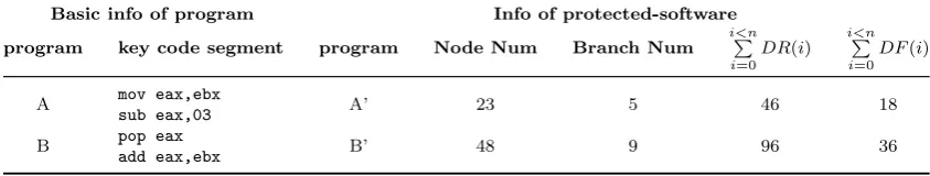
Table 2: The relevant information about the program
Basic info of program Info of protected-software
program key code segment program Node Num Branch Num
i<n
P
i=0
DR(i)
i<n
P
i=0
DF(i)
A mov eax,ebx
sub eax,03 A’ 23 5 46 18
B pop eax
add eax,ebx B’ 48 9 96 36
Notes: In the table, the number ofnwhich in
i<n
P
i=0
DR(i) and
i<n
P
i=0
DF(i) are equal to theNodeNum.
• DF(V i): the data flow relationship of basic block, Vi. This is used to measure the frequency of Vi’s information exchange. It is defined as DF (V i) = F lowin(V i) +
F lowout(V i), whereF lowin is the number of reading instruction in Vi and F lowout is
the number of writing instruction in Vi.
8.2.1. Example
Table2illustrates two code segments to be protected. These two code snippets have very similar structures because they both have one basic block and there is no branch within the basic block. As can be seen from the table, the code transformation applied by Dsvmp
leads to significant variances in the metric values. This indicates that the transformed code segments have distinct code structures. The metric value calculation is described as follows. We use the following formula to quantify the code structure information, SInf orX, for
a given piece of code, X, after code obfuscation.
SInf orX =N odeN umX +BranchN umX +
i<n
P
i=0
(DR(i) +DF(i))
Applying this formula to the transformed code segments, A’ and B’, listed in Table 2, we get :
SInf orA0 =N odeN umA0 +BranchN umA0 +
i<n
P
i=0
(DR(i) +DF(i)) = 23 + 5 + (46 + 18)
= 92
SInf orB0 =N odeN umB0 +BranchN umB0 +
i<m
P
i=0
(DR(i) +DF(i)) = 48 + 9 + (96 + 36)
= 189
From SInf orA0 and SInf orB0, we can calculate the similaritySDif f, for the two piece
of code, A’ and B’, as:
SDif f = |SInf orA0 −SInf orB0|
SInf orA0+SInf orB0
= 97
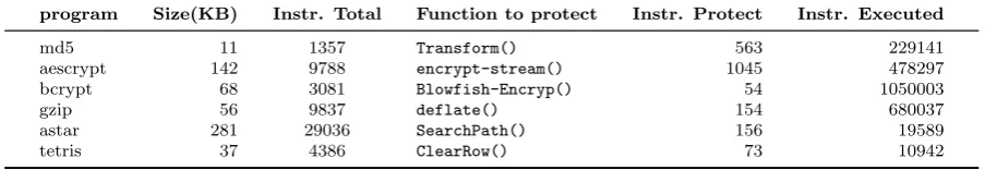
Table 3: Information of the benchmarks
program Size(KB) Instr. Total Function to protect Instr. Protect Instr. Executed
md5 11 1357 Transform() 563 229141
aescrypt 142 9788 encrypt-stream() 1045 478297
bcrypt 68 3081 Blowfish-Encryp() 54 1050003
gzip 56 9837 deflate() 154 680037
astar 281 29036 SearchPath() 156 19589
tetris 37 4386 ClearRow() 73 10942
Notes: The 3rd column shown the total number of target program instructions. The 4th column of the table gives the function to be projected and the 5th column shows the number of instructions of the function. The number of instructions got executed with the critical functions while processing the test file, and shown in the last column of the table.
Therefore, the quantified code structure similarity between A’ and B’ is 34.5%. This example shows that Dsvmp can significantly increase the dissimilarity of code structures
even for simple code segments.
9. Performance Evaluation
We now evaluate the performance of Dsvmp using six applications and compare it with
two commercial VM-based protection systems.
9.1. Evaluation Platform and Benchmarks
We evaluated Dsvmp on a PC with an 3.0 GHz Intel Core-i3 Duo processor and 8GB of
RAM. The PC runs the Windows 10 operating system.
We evaluated our approach using four widely use applications, md5, aescrypt, bcrypt,
gzip. We used these applications to process a test text file. The size of the file is 26 KB. In addition to the four applications, we also evaluate our approach on two interactive gaming applications: “AStar”, a maze pathfinding game using the A* algorithm, and“Tetris”, a classic graphics combination game [18]. Figure 9 shows the “AStar” maze barrier setting and route finding results, and the clear row operations of “Tetris”. Table 3 gives some information of the protected code regions for each benchmark. The total number of target program instructions are shown in the 3rd column in Table 3. The 4th column of the table gives the function to be projected and the 5th column shows the number of instructions of the function. Finally, we use the Intel Pin tools [19] to calculate the number of instructions get executed within the protected functions while processing the test file. The result is shown in the last column of the table.
9.2. Code Size and Runtime Overhead 9.2.1. Code size
For each target benchmark, we will choose a core function to protect. We do so by inserting a set of specific SDK (“STARTSDK” and “ENDSDK”) at the beginning and end of the target function in the compiled program binary. We applied Dsvmp to the target
function and repeated the process for 10 times. For each protection run, we used a different number of VM configurations.
Figure 10 shows how the Dsvmp multi-VM scheme affects the code size. As described
Figure 9: The interaction interface of the “AStar” and “Tetris”.
0 1 2 3 4 5 6 7 8 9 10
0 100 200 300 400
C
ode s
iz
e
(KB
)
md5 aescrypt bcrypt gzip astar tetris
Figure 10: The impact of code sizes forDsvmpconfigurations with a different number of VMs. The number of horizontal axis is the configuration of the VMs, “0” is the original program.
not supervising that the code size of the protected program grows as the number of VM increases. In general, the code size grows as the number of VMs increases, because the block of PE executables are usually follow a certain alignment value (such as, 4096 or 512 byte) [16]. Moreover, we can see that there is a strong correlation between the code size and the number of protected instructions. This is why the code size of “aescrypt” grows fastest than others – as it has the largest number of protected instructions (see Table 3). For the same reason, the code size of “bcrypt” grows slower than other programs, as this benchmark has the least number of protected instructions. Overall, the code size growth (a few hundreds KB in our experiments) is modest as typically we only need to protect the core function or a core algorithm of an application.
9.2.2. Runtime overhead
[image:18.595.182.414.341.464.2]0 1 2 3 4 5 6 7 8 9 10 0
0.5 1 1.5 2 2.5 3 3.5 x 10
5
A
verag
e R
unt
ime
(
us
)
md5 aescrypt bcrypt gzip
(a)
0 1 2 3 4 5 6 7 8 9 10 0
0.5 1 1.5
2 x 10
4
A
verag
e R
unt
ime
(
us
)
astar tetris
[image:19.595.72.526.118.261.2](b)
Figure 11: The average runtime of target benchmark when protected with different VMs. The number of horizontal axis is the configuration of the VMs, “0” is the original program. Because the runtime overhead of “AStar” and “Tetris” is much smaller than the other four benchmarks, in particular, their experimental data are shown separately in (b) in order to observe their variation.
Table 4: Possible execution path statistics
Basic configuration m, for differentNV M configurations
program ND n 1 2 3 4 5 6 7 8
md5 5 6175 66175 116175 166175 216175 266175 316175 366175 416175 aescrypt 5 8014 68014 118014 168014 218014 268014 318014 368014 418014
bcrypt 5 585 6585 11585 16585 21585 26585 31585 36585 41585
gzip 5 1271 61271 111271 161271 211271 261271 311271 361271 411271 astar 5 1502 61502 111502 161502 211502 261502 311502 361502 411502
tetris 5 696 6696 11696 16696 21696 26696 31696 36696 41696
Notes: The specific calculation process is described in section 8. WhereND is the number of dispatcher,NV M is the number
of VMs, andnis the number of handler scheduling.
interaction delay, we only calculate and collect the average runtime of the target operations (pathfinding and row clear).
The results are depicted in Figure11. We see an increase on the runtime overhead when using multiple VMs but the overhead becomes stable from 3 VMs onward. which shows that the majority of average runtime. Except for the handler’s normal interpretation of the time spent on the execution, the main runtime overhead comes from the the switch time between different VMs. The overhead of VM switch is stable so that it does not significantly increase when using 3 or more VMs. We notice that the overhead of VM switch for using two VMs is not significant. This is because our scheme does not frequently switch the VM under a 2-VM configuration. Besides, we found that the greater the number of protected instructions get executed at runtime the greater the runtime overhead will be. This explains why “bcrypt” has a much higher runtime overhead than other benchmarks.
9.3. Structural diversity
9.3.1. Possible execution path statistics
In the previous section, we have discussed how to calculate the number of optional execution paths for a code region protected by Dsvmp (see Section 8.1). We adjust the
[image:19.595.76.518.354.443.2]1 2 3 4 5 1 2 3 4 5
1 2 3 4 5 0 0.1 0.2 0.3 0.4 0.5 0.6 0.7 0.8 0.9 1 M ul ti pl e V M S w it ch No Switch Switch
Test-2VM Test-3VM Test-4VM
(a)
0 1 2 3 4 5 6
1600 1620 1640 1660 1680 1700 1720 1740 Ins truc ti on E xec ut ed
Test-2VM Test-3VM Test-4VM
(b)
Figure 12: (a) is the probability distribution of multiple VMs switching for multiple runs. The legend “switch” donates the number of times a VM has been switched to another, and the “no switch” means the VM remains unchanged. (b) is the number of instructions changes across runs due to the VM switch.
for different benchmarks. We then calculate the values of m under different configurations for these benchmarks, based on the formula presented at Section8.1. Detailed experimental data are shown in Table4. From the experimental data, we can clearly see that the number of optional paths for each benchmark is a huge number, and the program protected by
Dsvmp rarely follows the same execution path across different runs. At the same time,
through the previous experimental data we found that the number of runtime instructions for the target code is much larger than the number of its original instructions (see Table 3). This is because the critical method is executed multiple times at runtime. Therefore, even in a single run for a program protected by Dsvmp, calls to the critical function is likely to follow different execution paths during a single run.
9.3.2. Multi-VM switching experiment
In order to evaluate the impact of multi-VM switching on program execution, we conduct experiments on using a micro-benchmark, “test.exe4. Here we only protect one instruc-tion “mov eax, 1234567” of the application, in order to isolating other scheduling effects. In this experiment, we do not perform handler obfuscation and used only one dispatch-er in the protection process. This can minimize the impact of irrelevant factors. We use three VM configurations, 2-VM, 3-VM and 4-VM, to protect the target program. For each configuration, we run the program execution 5 times to collect the relevant information.
Figure12(a) shows the VM switching frequency information of “test.exe” for the five runs. We observe that the frequency of VM switching is low when 2 VMs are use. However, the frequency increases by 75% when 3 or 4 VMs are used. Through the experiment we found that the impact of 2-VM on the number of instructions gets executed at runtime is less than 3-VM and 4-VM. This is depicted in Figure 12 (b). Essentially, the number of instructions gets executed can reflect the runtime overhead. This explains why the 2-VM configuration has a smaller effect on runtime overhead in Figure 11.
[image:20.595.78.527.122.269.2]0 10 20 30 40 50 60 70 1
2 3
V
irt
ua
l M
achine ID
run1 run2 run3
(a)
0 10 20 30 40 50 60 70
1 2 3 4
V
irt
ua
l M
achine ID
run1 run2 run3
[image:21.595.62.533.114.200.2](b)
Figure 13: Dynamic VM switching for executing protected code regions. There are a total of 69 handler schedules. The y-axis shows the VM selected in each schedule. Different lines show the VM switches across runs for a 3-VM (a) and a 4-VM (b) configuration.
9.3.3. Perform path runtime diversity
In the course of the above experiment, we also collected the ID of the VM where the handler was executed each time. Figure 13 shows the switching of the VM for three runs. The data in (a) and (b) are from the test program with 3-VM and 4-VM configurations, respectively.
As can be clearly seen in the figure, VMs are randomly selected across different runs, and the execution path of the 3 runs is not the identical. For each dispatch loop, the dispatcher will randomly selects a VM to enter and schedules the corresponding handler. As mentioned before, the handlers set in each VM is obfuscated with different obfuscation schemes. Thus, the internal structure of the handler dispatched from different VMs during each run is different. The experimental results show that the execution path of a protected program exhibit strong diversity. Combined with various handler sets, the target program protected byDsvmp will have temporal diversity [10].
9.4. Comparisons with state-of-the-arts
We also compared Dsvmp against two commercial VM protection systems, Code Vir-tualizer (CV) [3] and VMProtect (VMP) [4], in terms of code sizes and runtime overhead. We adopt a customized protection scheme when using CV to protect the target program. Specifically, this scheme uses the Medium opcodes obfuscation options, and does not use the “Strip Relocation”, “Re-Virtualization” and other additional code obfuscation schemes. Doing so allow us to keep the runtime and code-size overhead of the CV scheme at a mod-erate level, in order to provide a fair comparison. For VMP, we use two types of schemes to protect the target program,Maximum-protection which provides the strongest protection (noted as VMProtect-Maximum-protection), and Maximum-speed (noted as VMProtect-Maximum-speed), which aims to reduce the overhead. For Dsvmp, We use a configuration of 5 VMs,Dsvmp-5VM, in this experiment. This is because the code-size overhead of 5-VM
configuration is moderate.
9.4.1. Code size
Figure14 shows the impact on code size of several VM-based protection systems. From the figure we can see that Dsvmp has a similar code-size overhead, if not smaller, when
md5 aescrypt bcrypt gzip astar tetris 0
100 200 300 400 500
C
ode S
iz
e
(KB
)
Original DSVMP-5VM Code Virtualizer
[image:22.595.115.481.110.421.2]VMProtect-Max-protection VMProtect-Max-speed
Figure 14: Code size comparisions.
md5 aescrypt bcrypt gzip astar tetris 0
0.5 1 1.5 2 2.5 x 10
6
A
verag
e R
unt
ime
(
μ
s)
DSVMP-5VM Code Virtualizer
VMProtect-Max-protection VMProtect-Max-speed
astar tetris 0
2 4 6 8 10 x 10
4
[image:22.595.117.481.113.246.2]Figure 15: Average runtime overhead comparisions.
Table 5: The average runtime overhead(ms)
program Original DSVMP
5VM
VMProtect Max-Speed
VMProtect Max-Protect
Code Virtualizer
md5 1.603 64.229 73.660 141.179 803.302
aescrypt 6.550 154.720 257.718 1903.458 623.452
bcrypt 4.544 298.415 252.655 1899.968 2051.708
gzip 3.963 169.107 368.599 1923.022 1110.598
astar 8.806 16.992 18.210 91.691 58.705
tetris 0.668 1.565 4.811 13.393 12.012
Average 4.357 117.505 162.609 995.452 776.630
Notes: The average data for the last row is the average runtime for 6 benchmarks for each protection scheme.
[image:22.595.110.486.475.578.2]D
SV
M
P
-5
VM
0 10 20 30 40 50 60 70 80 90 100 110 120 130
1 2 3
0 0.05
C
o
d
e
V
ir
tu
al
iz
er
0 5 10 15 20 25 1
2
3 0.05
0.25
VM
P
ro
te
ct
0 2 4 6 8 10 12 14 16 1
2
3 0.1
[image:23.595.73.531.112.241.2]0.2 0.3
Figure 16: Calling frequencies for handlers across runs per scheme formd5. The x-axis shows the number of handlers observed, and the y-axis represents three individual runs.
9.4.2. Runtime overhead
The average runtime overhead of the three schemes is given in Figure 15. This diagram shows that the runtime overhead of Dsvmp and VMProtect-Maximum-speed are compara-ble, which is smaller than CV and VMProtect-Maximum-protection. Code protected under CV and VMProtect-Maximum-protection has the most expensive runtime overhead, which on average is higher than Dsvmp and VMProtect-Maximum-speed. Detailed experimental
data are shown in Table 5. Specifically, the average runtime overhead brings by CV and VMProtect-Maximum-protection are 7 and 9 times larger thanDsvmp-5VM respectively.
9.4.3. Diversity evaluation
Recall that one of the design goals of Dsvmp is to increase the diversity of program execution. To evaluate this design goal, we record how frequent a handler is called across different runs per protection scheme. This experiment was performed on themd5application. We ran the obfuscated program three times and used a 5-VM configuration for Dsvmp. The results are shown in Figure 16. As can be seen from the heat maps, CV and VMP use fewer handlers than Dsvmp; and the calling frequency of each handler remains unchanged
across different runs. By contrast, when usingDsvmp, the handler frequency changes across runs, resulting in different ‘hot’ handlers across runs. This example shows that Dsvmp can
increase the diversity of program execution when compared to CV and VMP, because it uses more handlers and the calling frequency of handlers varies across runs.
Intuitively, the stronger the variation of the handler address offsets across runs, the stronger the non-deterministic behavior the program will exhibit across runs. To collect the dynamic addresses information, we used the Intel Pin [19] binary instrumentation tool instrument the code to gather the handler addresses during runtime. This experiment was performed on themd5 application and we ran the obfuscated application three times.
Figure 17 (a) shows that the handler address offsets change across runs when using
Dsvmp. By contrast, CV and VMP (Figure 17 (b)) use a static set of handlers, and the
0 10 20 30 40 50 60 70 80 90 100 -2
-1 0 1 2 x 10⁴
D SV M P-5 VM H an d ler ad d res s o ff
set Run 1 Run 1 Run 3
(a) Code protected byDsvmp
0 10 20 30 40 50 60 70 80 90 100 -4
-2 0 2 4 x 10
4 CV & V M P H an d le r ad d re ss o ff se t
Code Virtualizer VMProtect
[image:24.595.86.506.112.334.2](b) Code protected by CV and VMProtect
Figure 17: The address offset of the scheduled handlers in time order during different runs formd5protected under different schemes. The x-axis shows the part of the handler’s scheduling at different times. Where applications protected by Code Virtualizer and VMProtect, always follows a single and fixed handlers execution sequence during different runs, so there’s only one curve.
the knowledge gathered during the previous runs to perform reverse engineering, because the handler sets to use may change in future runs.
To sum up, compared with two commercial tools protection programs, which always follow a fixed execution path for the same input across different runs, the program protected byDsvmp follows dynamically changing execution paths in different runs.
9.4.4. User study
We follow a similar evaluation methodology described in [20] to conduct a small scale user study to evaluate the strengthen of our protection scheme. Our user study involved 15 students from the host institution. Among the 15 students, there are 2 senior PhD students and 13 postgraduate (Master) students, of which 7 students are female and 8 are males. The students were studying a computer science degree in cyber security at the time this experiment was conducted. Our participants all have hands-on experience on software reverse engineering. This experiment was approved by the research ethics board (REB) of the host institution.
In this experiment, all participants acted as an attacker. They were asked to reverse engineer themd5 application, which has been obfuscated by three code protection schemes:
Dsvmp, CV and VMP. In this experiment, we use a 5-VM configuration for Dsvmp. The
participants tried to accomplish three tasks described as follows. Each participant was given 72 hours to accomplish a task.
Table 6: The number of participants who have successfully accomplished a task.
Code Obfuscation Schemes Task 1 Task 2 Task 3
DSVMP-5VM 11 3 3
CV 11 10 10
VMP 11 8 8
• Task 2: Given the entry point address of the VM interpreter, find the address of the dispatcher;
• Task 3: Given the address of the dispatcher, find out what handlers have been executed during runtime; and record the handler addresses.
It is to note that these tasks represent the essential steps that an attacker must perform in order to reverse engineer a code region protected under a VM-based code obfuscated scheme. Therefore, the fewer people success in a task, the stronger the protection a scheme will provide. We also remark that these tasks are relatively simple, because the protected code region only contains a handful number of native instructions; and accomplish these tasks may not lead to a successful attack, because an attacker still needs to recover the functionalities of the target code. Nonetheless, this experiment allows us to compare the protection strengthen of our approach against commercial counterparts.
Table 6shows how many participants have successfully accomplished a task. Intuitively, the fewer participants could accomplish a task under a protection scheme, the stronger protection the scheme has provided. Task 1, finding the entry point address of the VM interpreter, is trivial to our participants (who already have hands-on experience on VM-based code obfuscation). Most of our participants could do so for all schemes. Tasks 2 and 3 appear to be harder. When using Dsvmp, there are only three participants managed to
accomplish them. This is because the dynamic scheduling structure employed by Dsvmp
makes it difficult to trace the addresses of the dispatcher and the handlers. To perform tasks 2 and 3 on CV and VMP seems to be easier. As we can see from the table, 10 participants could successfully finish these tasks when using CV, and 8 participants were able to do so when using VMP. This experiment confirms thatDsvmpindeed increases the cost of reverse
engineering when compared to CV and VMP.
To investigate these results further we recorded the correct dispatcher and handler ad-dresses collected by the different participants in task 2 and 3, respectively. The results are shown in Table 7. Each data item of this table is a two-tuple, (ND, n), where ND is the
number of the correct dispatcher addresses obtained in task 2, andn represents the number of the handler addresses recorded in task 3. Experimental results show that CV and VMP only have a single dispatcher, i.e. the tuple for CV and VMP in Table 7 is (1, 14630429) and (1, 2143262). This means that once the dispatcher address is located, it would be easy to extract the entire handler set. For Dsvmp, however, there can be multiple dispatchers
dispatch-Table 7: The dispatcher and handler addresses collected by different participants
Schemes P1 P2 P3 P4 P5 P6
DSVMP-5VM (3, 1057219) (5, 2463571) (1, 24037) (1, 89692) (0, 0) (2, 991895)
CV (1, 14630429) (1, 14630429) (1, 14630429) (1, 14630429) (0, 0) (1, 14630429) VMP (1, 2143262) (1, 2143262) (1, 2143262) (0, 0) (0, 0) (1, 2143262)
Schemes P7 P8 P9 P10 P11
DSVMP-5VM (1, 88805) (1, 285717) (2, 477916) (5, 2463571) (5, 2463571) CV (1, 14630429) (1, 14630429) (1, 14630429) (1, 14630429) (1, 14630429) VMP (1, 2143262) (0, 0) (1, 2143262) (1, 2143262) (1, 2143262)
This table shows the data of the 11 participants (P1-P11) who have successfully found the VM entry address in task 1. Each data item of this table is a two-tuple, (ND,n), whereNDis the number of the correct dispatcher addresses obtained in task 2,
andnrepresents the number of the handler addresses recorded in task 3. Number “0” in a tuple means that the participant did not get the data or got the wrong data.
er addresses (see task 2 in Table 6). As a consequence, most of them failed to locate the complete set of handlers. Moreover, since each dispatcher is randomly selected at run time by Dsvmp, the handler sequences collected by the same dispatcher addresses are different
across runs. This mechanism further increase the difficulty of code reverse engineering.
10. Related Work
Early work on the binary code protection relies on simple encryption and obfuscation methods, but they are vulnerable to the sophisticated, diversified attacks developed over the past years. Traditionally, techniques like junk instructions [21], packers [22, 23], are used to protect software against attacks based on disassembly and static analysis. There are also other code protection techniques like code obfuscation [24], control flow and data flow obfuscation [25, 26, 27], all aim to obfuscate the semantic and logical information of the target program. In practice, these approaches are often used in combination to provide stronger protection. Dsvmp also leverages some of the code obfuscation techniques
developed in the past for code protection. In recent years, there are many different code protection programs has been constantly put forward. Some research is devoted to CFI (Control Flow Integrity) protection, for example, Zhang et al. [28] and van der Veen et al.[29] provide fine-grained CFI systems against modern control flow hijacking attacks based on ROP (Return-Oriented Programming) and more advanced code reuse attacks [30]. And some studies consider Code Randomization protection, such as Stephen et al. presents a practical, fine-grained code randomization defense, called Readactor, resilient to both static and dynamic ROP attacks [31].
This paper focus on researching the code virtualization protection, and there is a growing interest in using it to protect software from malicious reverse engineering. Similar to our code virtualization approach is the work conducted by the following studies.
[image:26.595.101.495.131.231.2]reverse engineer a layer of the interpreter before moving to the next layer, which increases the cost of attacks. The multi-stage and nested interpretation process, however, is bound to bring expensive time overhead.
Averbuchet al. [32,33] introduces an encryption and decryption technology on the basis of VM-based protection. This approach uses the AES algorithm and a customize encryption key to encrypt the virtual instructions. During runtime, the VM will decrypt the virtual instruction and then dispatch a handler to interpret the virtual instructions. But it requires hardware support, and the decryption key is stored in the CPU and the attacker cannot get it, so it can effectively hinder the attacker’s reverse analysis.
Wang et al. [7] proposed a protection scheme to increase the time diversity of protected code regions to resist dynamic analysis. This is achieved by constructing several equivalent but different forms of sub program execution paths, from which a path will be randomly selected to execute at runtime. However, once generated, these sub paths are determined and the number is limited, so this approach only provides limited time diversity.
In the meantime, code analysis and deobfuscation techniques are constantly being in-troduced. Representative techniques such as Symbolic and concolic execution and taint analysis [34,35,36]. And Shoshitaishvili et al.[37] presents a binary analysis framework an-gr. Their work presents a systematized implementation of analysis techniques that proposed in the past, which allows other researchers to compose them and develop new approaches. Some of the common methods for analysing VM-based protection are as follows, Cooganet al. [38] puts forward a behavior based analysis method to analyze the important behavior of code, but it does not pay attention to how to restore the original code structure. It is often used to analyze Malware, due to the malicious code will inevitably interact with the system. Sharif et al. [39] used dynamic data-flow and taint analysis to identify data and extract the syntactic and semantic information about the bytecode instructions. Yadegari
et al. [40], by tracking the flow of inputs values, and then use semantics-preserving code transformations to simplify the logic of the instructions. These approaches, however, cannot restore the structure of the original code completely, because the analysis process is only for a dynamically executed sequence of instructions and does not cover all branches, and it depends on the results of the taint analysis. Therefore, they are usually performed and analyzed several times with different input to obtain a better structure information.
As a departure from prior work, Dsvmp presents a dynamic scheduling structure to
improve security for software. Dsvmp has integrated several novel techniques to increase
the diversity and uncertainly of program execution. These include using a control unit to diversify the execution path of bytecode handlers and using multiple VMs and dispatchers to randomly schedule instructions from multiple bytecode instruction sets. Integrating these techniques allows Dsvmp to provide a more diverse program execution structure compared
11. Conclusions
This paper has presented Dsvmp, a novel VM-based code protection scheme. Dsvm-p uses a dynamic scheduling structure and multiple VMs to increase diversity of program
execution. We have shown that code segments protected by Dsvmp rarely follow the same
execution path across different runs. The dynamic program execution brought by Dsvmp forces the attacker to have to use many trail runs to uncover the implementation of the pro-tected code region. As such,Dsvmp significantly increases the overhead and effort involved
in code reverse engineering. We have evaluatedDsvmpusing six real world applications and compared it to two state-of-the-art VM-based code protection schemes. Our experimental results show thatDsvmp provide stronger protection with comparable overhead of runtime
and code size.
Acknowledgment
This work was partially supported by projects of the National Natural Science Foun-dation of China (No. 61373177, No. 61572402, No. 61672427), the Key Project of Chi-nese Ministry of Education (No. 211181); the International Cooperation Foundation of Shaanxi Province, China (No. 2013KW01-02, No. 2015KW-003, No. 2016KW-034); the China Postdoctoral Science Foundation (grant No. 2012M521797); the Research Project of Shaanxi Province Department of Education (No. 15JK1734); the Research Project of NWU, China (No. 14NW28); the UK Engineering and Physical Sciences Research Council under grants EP/M01567X/1 (SANDeRs) and EP/M015793/1 (DIVIDEND); and a Royal Society International Collaboration Grant (IE161012).
References
[1] K. Kuang, Z. Tang, X. Gong, D. Fang, X. Chen, T. Xing, G. Ye, J. Zhang, Z. Wang, Exploiting dynamic scheduling for vm-based code obfuscation, in: 15th IEEE International Conference on Trust, Security and Privacy in Computing and Communications (TrustCom), IEEE, 2016.
[2] Themida,http://www.oreans.com/themida.php.
[3] Code virtualizer,http://www.oreans.com/codevirtualizer.php. [4] Vmprotect software. vmprotect,http://vmpsoft.com/.
[5] H. Fang, Y. Wu, S. Wang, Y. Huang, Multi-stage binary code obfuscation using improved virtual machine., in: Information Security, International Conference, ISC 2011, Springer, 2011, pp. 168–181. [6] M. Yang, L. S. Huang, Software protection scheme via nested virtual machine, Journal of Chinese
Computer Systems 32 (2) (2011) 237–241.
[7] H. Wang, D. Fang, G. Li, N. An, X. Chen, Y. Gu, Tdvmp: Improved virtual machine-based software protection with time diversity, in: Proceedings of ACM Sigplan on Program Protection and Reverse Engineering Workshop, 2014, pp. 1–9.
[8] H. Wang, D. Fang, G. Li, X. Yin, B. Zhang, Y. Gu, Nislvmp: Improved virtual machine-based software protection, in: 9th International Conference on Computational Intelligence & Security (CIS), 2013, pp. 479 – 483.
[9] N. Falliere, P. Fitzgerald, E. Chien, Inside the jaws of trojan, Tech. rep., Clampi. Technical report, Symantec Corp (2009).