Comparative Analysis of Modified fractal, L-Shaped and
Fractal Slotted Patch antenna with Novel Microstrip
Rectangular L-Shaped Slotted Patch Antenna for
Wireless Applications
Romeesa
M.Tech Scholar
Electronics and Communication Engineering Deptt.
Amritsar College of Engineering and Technology,
Amritsar
Narinder Sharma,
PhD
Associate Professor
Electronics and Communication Engineering Deptt.
Amritsar College of Engineering and Technology,
Amritsar
ABSTRACT
This paper investigates the comparison between existing antennas based on microstrip fractal technology with the proposed antenna. Comparison of proposed antenna has been made on the basis of number of frequency bands of operation and bandwidth. Proposed antenna is designed on the substrate of FR4 glass epoxy material with 1.6mm thickness and 4.4 dielectric constant. HFSS V13 simulator is used to design and simulate the proposed antenna. By observing the results of proposed antenna and existing antennas; it has been depicted that proposed antenna works on seven frequency bands of operation as compared to the existing antennas. Proposed antenna exhibist wideband characteristics and shows the bandwidth of 1959MHz, 700MHz and 2970MHz for respective frequency bands of operation. So, the proposed antenna can be efficiently used for practical wireless applications due to its wideband characteristics and more number of frequency bands of operation.
Keywords
L-slots, rectangular patch, circular patch, return loss, gain.
1.
INTRODUCTION
According to the IEEE standard an antenna can be defined as “a means for receiving or radiating electromagnetic waves”. The patch antenna has basically three layers: ground layer, substrate layer and conducting patch. An antenna is also called transducer that converts electric power into electromagnetic waves [1]. Patch antenna consists of ground on one side and patch on the other side of the substrate. Different types of feeding techniques are used in antenna technology to excite the patch. Patch antenna is most novel technology in antenna field. It is used in many recent technologies. In today‟s modern technology antennas are the basic and important elements which are used to make proper connections between transmitter and receiver. Antennas are used in different systems in different forms. In communication system low cost, small size, high gain and wide bandwidth antennas are required. Different types of antenna have been used in the modern communication systems such as microstrip patch antenna (MPA) and fractal antenna (FA) [2] [3][12].MPA has many applications in communication field such as satellite, missile, aircraft and spacecraft due to various advantages like low cost, easy installation better performance [4][13]. These antennas can be
mounted to metal bodies. Various types of feed techniques are used to excite the patch. These antennas work on above 100
MHz frequencies. Substrate, patch and ground are the basic component of patch antenna. Patch is present on the one side of substrate and ground is on the other side of substrate. To improve the performance of antenna various types of modifications are done in basic geometry like slots in the patch and defected ground plane etc [5].Fractal antennas are used to overcome limitations of patch antenna such as limited bandwidth, size and efficiency. Idea of fractal antenna came from fractals present in nature. Fractal antennas are considered using fractal geometries that have properties like space filling, self-similarity and difficulty in their formation [6]. Shapes that exist in nature shows space filling and self-similarity properties. These characteristics of fractal antenna are used for more bandwidth and high gain. According to dictionary definition fractal word derived from word „fractus‟ which means has broken into various sub parts. In fractal geometry, shapes and curves repeate itself [7].The fractal assumption techniques has been used for range reduce technique for all antennas types such as loops, dipoles, patches for the growth of fractal antenna. Fractal antennas allow antennas having different frequencies to design tetra-band and tri-tetra-band antennas with a same gain and a very small size factor as a conventional antenna [8].
2.
ANTENNA DESIGN
Figure 1: Modified Sierpinski carpet fractal antenna [9]
Figure 2: Microstrip patch antenna with L-shaped slots [10]
Figure 3: Circular microstrip patch antenna with fractal slots [11]
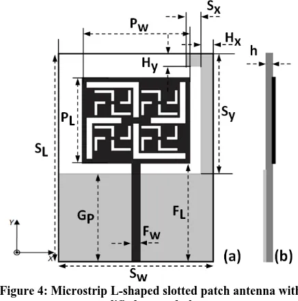
In the proposed design of antenna rectangular patch, L-shaped slots and partial/modified ground plane are used.By using all these techniques, a novel design of antenna is presented in this paper. In this design, a low cost FR4 glass epoxy substrate has been used with a thickness of 1.6 mm, dielectric constant 4.4 and a resonant frequency of 2.45 GHz. The length of patch PL=29mm and width of patch PW=37mm is derived from
equations (1) to (5). The modified ground plane has been employed in the geometry of designed antenna to enhance the performance of antenna in terms of return loss and bandwidth.
Geometry of proposed antenna is shown in Figure 4 and the parametric dimensions are tabulated in Table 1.
[image:2.595.63.269.261.641.2]Figure 4: Microstrip L-shaped slotted patch antenna with modified ground plane
Table 1: Parametric values of proposed antenna
Antenna design parameters Description Values (mm)
PL Length of patch 29.0
PW Width of patch 37.0
FL Length of feed line 33.0
FW Width of feed line 3.0
SL Length of substrate 70.0
SW Width of substrate 53.0
SX Width of horizontal stub 5.0
HX Width of vertical stub 3.5
SY Length of vertical stub 38.5
HY Length of horizontal stub 3.5
GP Length of partial ground
plane
31.5
h Thickness of substrate 1.6
2
1
2
r o Wf
c
P
(1)2 1
12
1
2
1
2
1
W r r reffP
h
(2)reff o eff
f
c
L
2
(3)
8
.
0
258
.
0
246
.
0
3
.
0
412
.
0
h
P
h
P
h
L
W reff W reff
(4)L
L
[image:2.595.313.543.362.751.2]3.
RESULT AND DISCUSSIONS
3.1 Return loss
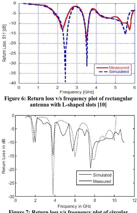
This section presents the results of different types of antenna along with the results of proposed antenna. It has been observed that the modified Sierpinski carpet fractal antenna works on six frequency bands of operation such as 4.85 GHz, 5.25 GHz, 6.09 GHz, 6.81 GHz, 8.44 GHz and 9.12 GHz with acceptable value of return loss and VSWR. The return loss versus frequency plot of modified Sierpinski fractal antenna is shown in Figure 5. But as we observe the resonant frequency the modified fractal antenna does not cover the designed frequency range which is the main drawback of this antenna. Similarly, by analyzing the rectangular antenna with L – shaped slots; it is observed that it works on three distinguished frequency bands of operation such as 2.4 GHz, 3.5 GHz and 5.5 GHz as shown in Figure 6. From Figure it has been contemplated that antenna exhibits low bandwidth of few MHz (narrow bandwidth). Likewise; the circular antenna with fractal slots exhibits four frequency bands of operation such as 1.9 GHz, 3.78 GHz, 6.07 GHz and 7.87 GHz as reported in Figure 7. By observing the return loss versus frequency plot of circular antenna it is concluded that there is large variations in the simulated and measured results. It is also observed that the lower frequency band does not exhibit -10 dB criteria of return loss. All the existing antennas are fabricated and the results are compared to the simulated antennas. But on analyzing the antenna it has been observed that some of the results are not satisfactory. So to overcome these drawbacks of existing antennas the novel design of rectangular antenna with L-slots and modified ground plane is designed to achieve wideband and multiband characteristics. The fabricated prototype of proposed antenna is shown in Figure 8 and the comparison of simulated and measured frequency plot is shown in Figure 9.
[image:3.595.317.540.77.422.2]Figure 5: Return loss v/s frequency plot of modified Sierpinski carpet fractal antenna [9]
[image:3.595.320.540.79.230.2]Figure 6: Return loss v/s frequency plot of rectangular antenna with L-shaped slots [10]
[image:3.595.329.529.451.613.2]Figure 7: Return loss v/s frequency plot of circular antenna with fractal slots [11]
Figure 8: Fabricated prototype of proposed antenna front view and back view
[image:3.595.57.292.460.635.2]standards (DCS 1.71 – 1.88 GHz and PCS 1.85 – 1.99 GHz), UMTS (1.92 – 2.17 GHz), Bluetooth (2.41 – 2.49 GHz), WiMAX (3.3GHz – 3.7 GHz, 5.25 – 5.85 GHz), WLAN (5.15 – 5.85 GHz), X-band satellite applications and point to point high speed wireless communication (5.93 GHz – 8.5 GHz). The comparisons of the results of proposed antenna with other existing antennas are delineated in Table 2.
Figure 9: Return loss v/s frequency plot of novel design of antenna with modified ground plane
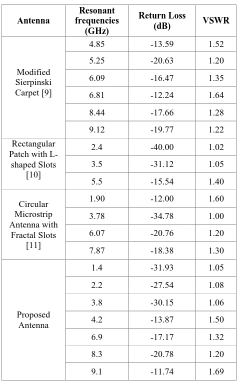
Table 2: Comparison of the results of proposed antenna with existing antennas
Antenna
Resonant frequencies
(GHz)
Return Loss
(dB) VSWR
Modified Sierpinski Carpet [9]
4.85 -13.59 1.52
5.25 -20.63 1.20
6.09 -16.47 1.35
6.81 -12.24 1.64
8.44 -17.66 1.28
9.12 -19.77 1.22
Rectangular Patch with L-shaped Slots
[10]
2.4 -40.00 1.02
3.5 -31.12 1.05
5.5 -15.54 1.40
Circular Microstrip Antenna with
Fractal Slots [11]
1.90 -12.00 1.60
3.78 -34.78 1.00
6.07 -20.76 1.20
7.87 -18.38 1.30
Proposed Antenna
1.4 -31.93 1.05
2.2 -27.54 1.08
3.8 -30.15 1.06
4.2 -13.87 1.50
6.9 -17.17 1.32
8.3 -20.78 1.20
9.1 -11.74 1.69
3.2 GAIN
The gain is also a vital performance parameter of antenna. It has been observed that the existing antennas; the modified Sierpinski carpet antenna [9] and antenna with L-shaped slots [10] do not show any value of gain at resonant frequency bands of operation. Whereas, the circular microstrip antenna with fractal slots [11] exhibits the gain of 9.19 dB, 3.04 dB, 5.19 dB and 5.39 dB at the frequency bands of 1.9 GHz, 3.78 GHz, 6.07 GHz and 7.87 GHz respectively. In the designed antenna, gain is analyzed at all the frequency bands of operation. Proposed antenna exhibits the gain 2.41 dB, 2.81 dB, 2.02 dB, 8.84 dB, 3.85 dB, 5.37 dB and 3.57 dB at the respective frequency bands of operation. Antenna with fractal slots [11] shows the high value of gain; but exhibits less bandwidth and number of frequency bands in comparison to the proposed antenna. So, we can claim that the proposed antenna is suitable for different wireless applications.
4. CONCLUSIONS
Comparison of existing [9, 10, 11] antennas has been made with the proposed antenna in this paper. On analyzing the performance of proposed antenna it has been depicted that it resonates on more number of frequency bands and also exhibits wideband characteristics as compared to the existing antennas. Proposed antenna shows the bandwidth of 1959 MHz, 700 MHz and 2970 MHz at respective frequency bands of operation. It also shows the acceptable value of gain at respective frequency bands. So, it can be concluded that the proposed antenna is more suitable for practical wireless applications such as (DCS 1.71 – 1.88 GHz and PCS 1.85 – 1.99 GHz), UMTS (1.92 – 2.17 GHz), Bluetooth (2.41 – 2.49 GHz), WiMAX (3.3 – 3.7 GHz, 5.25 – 5.85 GHz), WLAN (5.15 – 5.85 GHz), X-band satellite applications and point to point high speed wireless communication (5.93 – 8.5 GHz).
5. REFERENCES
[1] J. S. Sivia, M. Singh, S. Rani, “Design and Analysis of Triple band Rectangular Microstrip Patch Antenna Array”. Advances in Circuits, Systems, Signal Processing and Telecommunications. pp. 97-101 ISBN: 978-1-61804-271-2
[2] G. Bharti, S. Bhatia and J. S. Sivia, “Analysis and design of triple band compact microstrip patch antenna with fractal elements for wireless applications,” International Conference on Computational Modeling and Security (CMS 2016), Elsevier Procedia Computer Science, Vol. 85, pp. 380-385, 2016.
[3] A. Kaur and N. Sharma , “A Quad band circular patch antenna with fractal elements for S-band and C-band applications,” International Journal of Computer Applications, Vol. 144, No. 3, pp. 1-4, 2016.
[4] Y. Bhomia, A. Kajla and D. Yadav “ V slotted triangular microstrip patch antenna”, International journal of electronics engineering, pp. 21-23, 2010.
[5] Y. S. H. Khraisat, “Design of four elements rectangular microstrip patch antenna with high gain for 2.4GHz applications”, Modern applied science, vol. 6, January 2012.
[image:4.595.47.287.378.759.2][7] D. Gupta and U. Barahadiya, “Rhombus shaped sierpinski carpet fractal antenna between 2-6 GHz”, International Journal of Recent research Aspects (IJRRA), vol. 2, Issue. 1, pp. 112-11, 2015, ISSN: 2349-7688.
[8] M. N. Iqbal, H. Ur Rahman and S.F. Jilani, “Novel compact wide band coplanar waveguide fed heptagonal fractal monopole antenna for wireless applications”, Wireless and Microwave Technology Conference (WAMICON), IEEE, pp. 1-3, 7-9 April 2013. [9] J. S. Sivia, G. Kaur and A. K. Sarao, “A modified Sierpinski carpet fractal antenna for multiband applications,” International Journal of Wireless Personal Communications, Vol. 95, Issue 04, pp.4269-4279, 8 march 2017.
[10]N. Mahmoud and E. K. I. Hamad, “Tri-Band Microstrip Antenna with L-shaped Slots for
bluetooth/WLAN/WiMAX Applications,” IEEE, 33rd National Road Science Conference (NRSC 2016), pp. 73 – 80, 2016.
[11]S. J. Sivia, G. Singh and G. Bharti, “Circular microstrip antenna with fractal slots for multiband applications,” Journal of Institution of Engineers India Series B, 23 march 2017.
[12]N. Sharma and V. Sharma “A journey of Antenna from Dipole to Fractal: A Review”, Journal of Engineering Technology (AEEE– American Society for Engineering Education), pp. 317-351, Vol. 6, Issue 2, July 2016, ISSN: 0747-9964.