© 2019, IRJET | Impact Factor value: 7.34 | ISO 9001:2008 Certified Journal | Page
226
Structural, Material and Modal Analysis of Ashok Leyland 2516 Model
Truck Chassis using ANSYS 14.0
Saumya Rastogi
1, Dr. L. P. Singh
21
M. Tech student, Production & Industrial Engg. (Mechanical Engineering Dept.), SHUATS, Allahabad, India
2
Associate Professor, Production & Industrial Engg. (Mechanical Engineering Dept.), SHUATS, Allahabad, India
---***---Abstract: Chassis acts as a backbone or framework of automobiles which supports power trains, transmission system, braking system etc. It is of various types such as ladder, backbone and monocoque. Their strength varies as the design of chassis and material varies. Chassis strength, deformations, load-carrying capacity, stresses generated, vibrations, etc. are many fields that require regular research to keep vehicles safe, to improve vehicles fuel efficiency and also should be cost effective. In present work structural, material and modal analysis is being done to find the rate of deformation, strength, deformations occurring at different frequencies etc. in order to find the best material which can fulfil the requirements of truck chassis. Software such as SOLIDWORKS 2016 and ANSYS 14.0 is used for modelling and analysing Ashok Leyland 2516 model truck. On comparing all the stress, strain, deformations of respective materials we can conclude that among three materials i.e. Structural steel, AISI4340, Carbon fibre which material is well suited to design a chassis frame
Key Words
:
ANSYS 14.0, Ashok Leyland 2516 model truck
Chassis, Ladder frame, SOLIDWORKS 2016
1. INTRODUCTION
Chassis is a French term which was used to connote the frame parts or the basic Structural of vehicle. The chassis is considered to be one of the most significant structure of an automobile. Chassis supports Power plant, Transmission System, Axles, Wheels and Tyres, Suspension, Controlling Systems like Braking, Steering etc., and also electrical system parts are mounted on the chassis frame. It not only provides safety to the vehicle but also reduce the noise level, vibration etc. There are many types of chassis such as Ladder chassis, Backbone chassis and monocoque chassis chassis. Further classification of chassis is based on location of engine, type of drive, type of Structural etc. Different type of chassis is used in different categories of vehicle. From past many years chassis strength and stability is a focused section for researchers. In the present work Chassis of Ashok Leyland 2516 model truck is taken for study. Structural Steel, AISI4340 and Carbon fiber is taken for modeling and analysis of chassis. From the results we can easily conclude that how different materials affects strength and life of
chassis .Composite materials are modern materials less in weight and more in strength. This study will clearly shows comparison between the conventional materials and modern materials.
1.1 OBJECTIVE OF PROJECT
The main objective of the project is to:
1. Design a chassis of Ashok Leyland 2516 model Truck with the help of SOLIDWORKS Software.
2. Conduct Stress Analysis in different sections of the chassis to find the load conditions and deformations in the designed chassis
3. Conduct Material and Modal Analysis by using different materials in order to obtain a correct material for the chassis, capable of reducing the weight and increasing the fuel economy and able to bear the payloads up to certain imit.
2. SPECIFICATION OF CHASSIS
Table1-Design Parameters
S.No. Parameters Dimensions
1. Model ASHOK LEYLAND 2516
2. Length of frame 7162 mm 3. Width of frame 863.6 mm
4. Ground
Clearance 260 mm
5. Gross Vehicle
Weight 25 tons
6. Kerb weight 6116 kg
7. Payload 15800 kg
© 2019, IRJET | Impact Factor value: 7.34 | ISO 9001:2008 Certified Journal | Page
227
[image:2.595.320.561.60.250.2]3. MATERIAL AND METHODS 3.1 Material Properties
Table 2-Material Properties
Properties Structural
steel AISI4340 Carbon fiber
Density
(kg/m3) 7850 7827 1500
Young’s Modulus (Pa)
2 x 10¹¹ 1.995 x 10¹¹ 1.5x10¹¹
Poisons
ratio 0.3 0.32 0.38
Tensile Ultimate Strength (Pa)
2.5 x 10⁸ 8.6184 x 10⁸ 6 x 10⁸
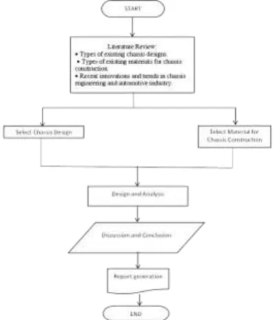
3.2 Methodology
In present work chassis of Ashok Leyland truck is modeled and analyzed by using SOLIDWORKS 2016 and ANSYS 14.0 software respectively. Structural steel, AISI4340 and carbon Fiber are the materials which are taken into consideration for analysis. Steps follow in methodology flowchart shown below:
Figure 1: Flowchart of Methodology
3.3 Design of Chassis Frame
The designing process requires CAD software like SOLIDWORKS 2016 .The chassis of Ashok Leyland is designed with unique measurements and as per the requirements of the category of vehicles. We have therefore designed the Ashok Leyland 2516 model truck chassis with exact measurements such as overall length, wheel base, track width, and other vehicle measurements. Different views are mentioned in order to understand the design easily.
Figure 2: SOLIDWORKS MODEL
As per the above-mentioned design requirements, the truck chassis designed as follows:
Step 1- After collecting all the dimensions a Structural of chassis is being created with the help of SOLIDWORKS .While sketching the Structural first of all, the plane i.e front, top or right is chosen.
Step 2- Now Longitudinal member is drawn which is C channel whose dimension is 228.60 x 88.90x 25.40 mm3.With the help of mirror, extrude etc. options , structure got its exact look.
Step 3-Next is to draw the cross members at the fixed distance as it is in actual structure. The cross member contain C Section, I section.
Step 4-Next is to provide supports to the cross members. The supports are C Section Structural and provide load bearing capacity to the Structural.
Step 5-After designing make sure the all the components should not merge in each other.
3.4 Analysis of Chassis
The step of analysis is as follows:
Step 1-Firstly, after opening the software we choose Static Structural option from the table listed at the left most part of the screen.
Step 2- Now as shown in the fig below a chart A appears .Starting from option number 2 Engineering data, here we choose material on which the analysis is performed
Step 3- After choosing the material now the CAD model of the Ashok Leyland 2516 model truck Chassis frame, is imported into this software from SOLIDWORKS 2016 where various inputs are provided to start the analysis process of this design.
Step 4-Ater importing contact between the all the members i.e. longitudinal member, cross members and supports is being provided. Here in the present analysis we have given bonded relationship between all the members.
[image:2.595.64.263.399.632.2]© 2019, IRJET | Impact Factor value: 7.34 | ISO 9001:2008 Certified Journal | Page
228
analysis are listed in the ANSYS 14.0 structural analysis report in APENDIX.
Step 6- For showing the deformations due to various frequencies we opt modal option from the main ANSYS window and a chart B appears on the screen .Here we solve the modal and get various results.
Step 7- Now generate the report.
[image:3.595.53.550.36.701.2]Step 8- Repeat this whole process for n number of materials on which analysis is to be performed and after generating the result compare all the result and choose the best material. Here in the present work I have used three materials – Structural Steel,AISI4340 and Carbon Fibre.
Figure 3: ANSYS Window
Figure 4: Meshed View (Nodes-288611, Elements- 47199)
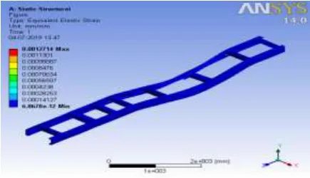
[image:3.595.324.545.92.370.2]1. Structural Steel Analysis-Solution of analysis is mentioned below
Fig 5: Equivalent Elastic strain
Fig 6: Directional Deformation
Fig 7: Equivalent Von –Mises Stress
Fig 8: Total Deformation
[image:3.595.61.276.278.510.2] [image:3.595.52.270.560.685.2]© 2019, IRJET | Impact Factor value: 7.34 | ISO 9001:2008 Certified Journal | Page
229
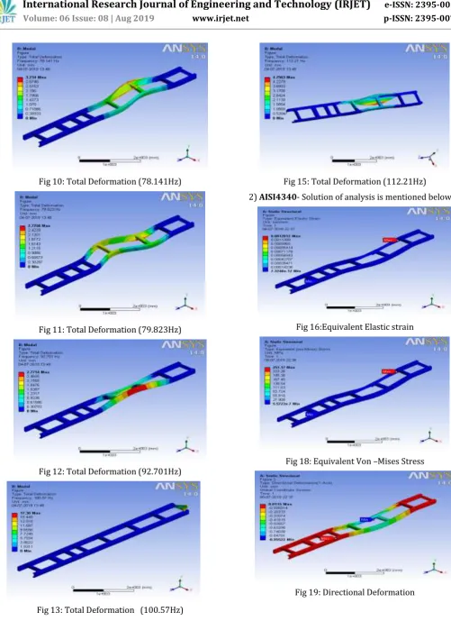
Fig 10: Total Deformation (78.141Hz)
Fig 11: Total Deformation (79.823Hz)
[image:4.595.46.548.51.741.2]Fig 12: Total Deformation (92.701Hz)
Fig 13: Total Deformation (100.57Hz)
Fig 15: Total Deformation (112.21Hz) 2) AISI4340- Solution of analysis is mentioned below:
Fig 16:Equivalent Elastic strain
Fig 18: Equivalent Von –Mises Stress
© 2019, IRJET | Impact Factor value: 7.34 | ISO 9001:2008 Certified Journal | Page
230
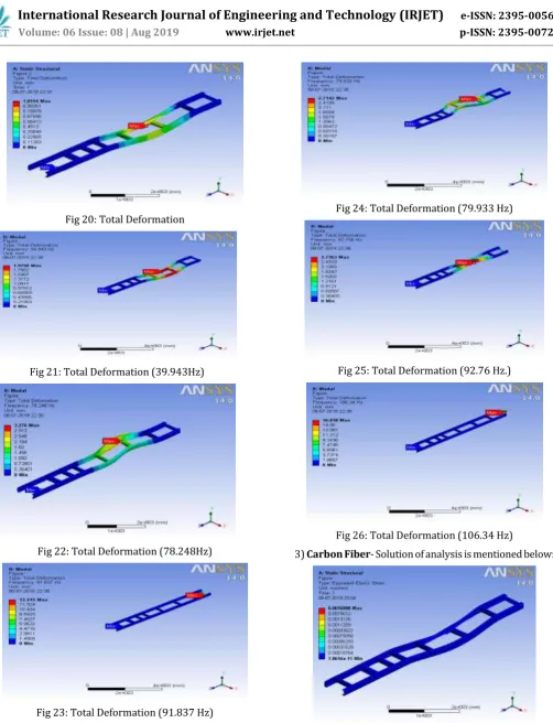
Fig 20: Total Deformation
Fig 21: Total Deformation (39.943Hz)
[image:5.595.55.558.42.699.2]Fig 22: Total Deformation (78.248Hz)
Fig 23: Total Deformation (91.837 Hz)
Fig 24: Total Deformation (79.933 Hz)
Fig 25: Total Deformation (92.76 Hz.)
Fig 26: Total Deformation (106.34 Hz)
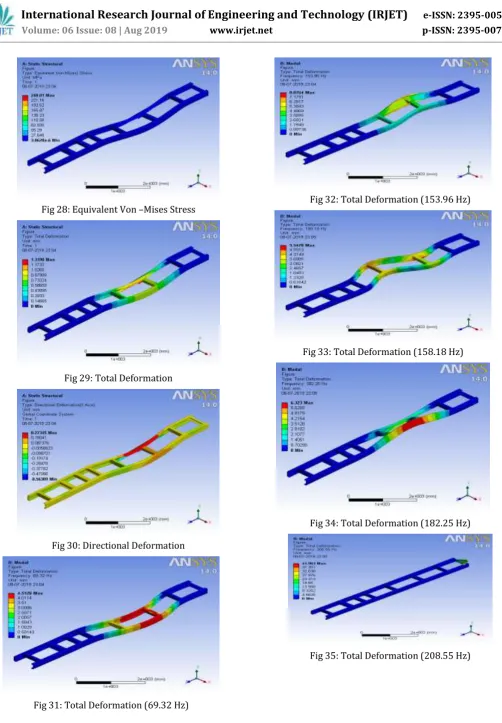
3) Carbon Fiber- Solution of analysis is mentioned below:
© 2019, IRJET | Impact Factor value: 7.34 | ISO 9001:2008 Certified Journal | Page
231
Fig 28: Equivalent Von –Mises Stress
Fig 29: Total Deformation
[image:6.595.50.553.41.765.2]Fig 30: Directional Deformation
Fig 31: Total Deformation (69.32 Hz)
Fig 32: Total Deformation (153.96 Hz)
Fig 33: Total Deformation (158.18 Hz)
Fig 34: Total Deformation (182.25 Hz)
© 2019, IRJET | Impact Factor value: 7.34 | ISO 9001:2008 Certified Journal | Page
232
Fig 36: Total Deformation (219.84 Hz)
4. Result & Discussion
A- Comparison Chart between materials
Table 3: Comparison Chart between Materials
Parameters /Materials
Structural steel AISI 4340 Carbon Fibre
Min. Max. Min. Max. Min. Max.
Equivalent Stress (MPa)
-5.8175e-7
252.26
5.5723e-7
251.17
3.8628e-6
240.81
Equivalent
Strain 6.8678e-12 0.0012714 7.3248e-12 0.0012812 7.0616e-11 0.0016888
Total Deformatio n (mm)
0 1.0106 0 1.0154 0 1.3198
Directional Deformatio n (mm)
-0.42125 0.20475 -0.95522
0.0115
-0.56389 0.27345
B-Modal Analysis Comparison Charts A-Structural Steel
Table 4: Structural Steel Modal Analysis
Frequency(Hz) Deformation
(mm)
34.867 1.9727
78.14 3.234
79.823 2.7258
92.701 2.7714
100.57 17.38
112.21 4.7563
B-AISI4340
Table 5: AISI4340 Modal Analysis
Frequency(Hz) Deformation
(mm)
34.943 1.9758
78.248 3.276
79.233 2.7142
91.837 13.415
92.76 2.7363
106.34 16.818
C-Carbon Fiber
Table 6: Carbon Fiber Modal Analysis
[image:7.595.310.562.119.424.2]
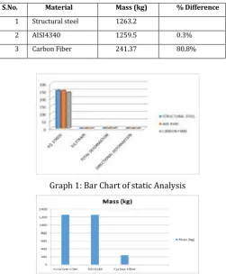
Table 7: % Reduction in Mass of Chassis
Graph 1: Bar Chart of static Analysis
Graph 2: Bar chart of material mass reduction potential From the above mentioned tables the result is clearly visible that maximum equivalent von-mises stress generated in Structural steel is more than AISI 4340 and Carbon Fibre. But if we see the total deformation result, then the value of carbon Fiber is more than the other two materials, but if we increase the thickness of the c-channel then the deformation will be become less .In case of directional deformation the maximum value occurs in AISI4340. From the modal analysis results indicate that a different deformation value appears in chart above. On comparing all the value study shows that at maximum frequency i.e. 219.84 Hz of carbon Fibre very less deformation occurs in the chassis. This shows that Carbon Fibre is safe for manufacturing truck chassis and its weight is approximately 80.8 % less than that of steel. This weight reduction also enhances fuel economy and reduces pollution.
5. CONCLUSION
Chassis strength and deformation under safe limits is very crucial parameter while designing and analysing chassis Structural. In this work, three materials i.e. Structural steel, AISI4340 and Carbon Fiber is selected for modelling and analysis and among them carbon Fibre gives best results. Composite material is very costly as compare to other metal used in auto vehicle chassis frame which incur some extra cost on the consumer .If cost is not considered then best alternative for the automobile and chassis frame is composite materials. The results of the modal analysis give a clear indication that the maximum stress induced is in steel and minimum stress induced is in composite material. It reduces
Frequency(Hz) Deformation
(mm)
69.32 4.5128
153.96 8.8764
158.18 5.5478
182.25 6.323
208.55 41.963
219.84 10.82
S.No. Material Mass (kg) % Difference
1 Structural steel 1263.2
2 AISI4340 1259.5 0.3%
© 2019, IRJET | Impact Factor value: 7.34 | ISO 9001:2008 Certified Journal | Page
233
weight of the chassis upto great extent which ensures fuel economy of the vehicle.
REFERENCES
[1] Anurag, Amrendra Kumar Singh, Akash Tripathi, Aditya Pratap Tiwari, Nitish upadhyay, Shyam Bihari Lal ,” Design And Analysis Of Chassis Frame”, Ijre | Vol. 03 No. 04 | April 2016
[2] David J. Andrea and Wesley R. Brown ,Material Selection Processes in the Automotive Industry ,December, 1993, Office for the Study of Automotive Transportation, University of Michigan Transportation Research Institute, Prepared for the Automotive Plastics Recycling Project Report Number: UMTRI 93-40-5
[3] Hirak Panchal, Khushbu C. Patel, Chetan S. Jadav,”Structural Analysis of Truck Chassis Frame and Design Optimization for Weight Reduction”, International Journal of Engineering and Advanced Technology (IJEAT) ISSN: 2249 – 8958, Volume-2, Issue-4, April 2013.
[4] Mohd Azizi Muhammad Nora,, Helmi Rashida, Wan Mohd Faizul Wan Mahyuddin “Stress Analysis of a Low Loader Chassis” Elsevier Ltd. Sci Verse Science Direct Procedia Engineering 41 ( 2012 ) 995 – 1001 [5] M. Ravi Chandra, S. Sreenivasulu, Syed Altaf Hussain, “Modeling and Structural analysis of heavy vehicle chassis made of polymeric composite material by three different cross sections”, International Journal of Modern Engineering Research (IJMER) Vol.2, Issue.4, July-Aug. 2012 pp-2594-2600 ISSN: 2249-6645
[6] Monika S.Agrawal,” Finite Element Analysis of Truck Chassis Frame”, International Research Journal of Engineering and Technology (IRJETVolume: 02 Issue: 03 | June-201) e-ISSN: 2395-0056 p-ISSN: 2395-0072 ©
[7] O. Ahmad Moaaz, Nouby M. Ghazaly “A Review of the Fatigue Analysis of Heavy Duty Truck Frames” American Journal of Engineering Research (AJER, Volume-3, Issue-10, pp-01-06, 2014.
[8] Patel Vijaykumar V, Prof. R. I. Patel, “Structural Analysis of Automotive Chassis Frame and Design Modification for Weight Reduction”, International Journal of Engineering Research & Technology (IJERT) Vol. 1 Issue 3, May - 2012 ISSN: 2278-0181 [9] Roslan Abd Rahman, Mohd Nasir Tamin, Ojo Kurdi
“Stress analysis of heavy duty truck chassis as a preliminary data for its fatigue life prediction using FEM” Jurnal Mekanikal December 2008, No. 26, 76 – 85.
[10] Shaik Neelophar Begum, S.P.Bhanu Murthy, 'MODELLING AND STRUCTURAL ANALYSIS OF VEHICLE CHASSIS FRAME MADE OF POLYMERIC COMPOSITE MATERIAL' International Research Journal of Engineering and Technology (IRJET), Volume: 03 Issue: 08 | Aug-2016, p-ISSN: 2395-0072
AUTHORS
Saumya Rastogi, M. Tech Scholar, Production & Industrial Engineering (Mechanical Engineering Department), SHUATS, Allahabad
Dr. L.P Singh