An Energy-Based Stochastic Model for Wireless Sensor
Networks
Yuhong Zhang1, Wei Li2
1 Department of Engineering Technology, Texas Southern University, Houston, USA 2 Department of Computer Science, Texas Southern University, Houston, USA
E-mail: [email protected], [email protected]
Received August 2, 2011; revised August 25, 2011; accepted September 6, 2011
Abstract
We propose an energy-based stochastic model of wireless sensor networks (WSNs) where each sensor node is randomly and alternatively in an active and a sleep mode. We first investigate the sensor model and derive the formula of the steady-state probability when there are a number of data packets in different sensor modes. We then determine important sensor’s performance measures in terms of energy consumptions, average data delay and throughput. The novelty of this paper is in its development of a stochastic model in WSN with ac- tive/sleep feature and the explicit results obtained for above mentioned energy consumption and performance characteristics. These results are expected to be useful as the fundamental results in the theoretical analysis and design of various hybrid WSNs with power mode consideration.
Keywords:Energy Efficiency, Wireless Sensor Networks, Energy-Based Stochastic Model
1. Introduction
Recently wireless sensor networks (WSNs) have re-ceived more and more attention due to their potential in civil and military applications as well as the advances in micro-electromechanical systems (MEMS) technology [1]. WSNs are composed of a large number of sensors equipped with limited power and radio communication capabilities. They can be deployed in extremely hostile environments, such as battlefield target areas, earth-quake disaster scenarios, and inaccessible spaces inside a chemical plant or nuclear facility to monitor environ- mental changes or other required information. There are a number of recent survey publications [2-9] on WSNs outlining several major directions in the area. Also, there are several papers and references therein which closely related to our current investigation. For example, the paper [10] in 2006 introduced a QoS supporting model and an optimal energy allocation in WSNs; the paper [3] in 2009 discussed the main directions to en-ergy conservation in WSNs; the paper [11] in 2011 in-vestigated several characteristics of active/sleep model in WSNs.
Once a WSN system has been designed, additional energy savings can be achieved using dynamic power management (DPM), which shuts down the sensor node
if no events occur. Every component in a node can be in different states; for example, the status of each sensor can be in active, idle, or sleep mode, so the sensor may transmit packets to and receive messages from others. Each node’s sleep status corresponds to a particular com- bination of the component power modes. Mathematically speaking, each sensor will have a finite number of dif- ferent statuses and the state space of each status is also different. The sensor node stays in each status or state for a random time and then transmits into another status or state and stays for another random duration. A special case is that each sensor will have only two different sta- tus, say active and sleep, similar as those in [12-14]. The sensor node alternatively stays in active or sleep status for a probability distributed duration. In this paper, we will concentrate on determining the steady-state pro- bability of data packets in a referenced sensor node and then the sensor’s energy consumption and the sensor’s performance characteristics.
2. Description of the Model
We will consider a wireless sensor network (or part of it) where each sensor may have different characteristics in performance. A sensor may be used as a sink, sensor head nodes or regular sensor node. Without loss of gen- erality, we introduce the assumption in a specific node (or head nose) and may temporally omit the node symbol in this section. The detailed assumptions and notations for a node under investigation of this sensor network are as follows.
Each node will have two major modes: active and sleep. In an active state, the sensor node is fully working—may generate data, process date (receive and relay/transmit) and keep in idle; in a sleep mode, the node cannot interact with the external world.
Each node have a finite capacity, say size of C, to store the data it generated or forwarded from other nodes for relaying purpose.
The sensor may stay in phase R of the active mode for a random time with exponential distribution with mean 1 . The sensor then may either move to phase N if there is at least one data packet waiting for processing or move to sleep mode when there is no data packets waiting. In the phase N of the active mode, the sensor node may only process (transmit or relay) data packets with random exponential time with mean 1 , and may not be able to generate data or receive any data for relay from other sensors. However, 1) in the phase R of the active mode if the total number of data packet is less than a threshold value K, the sensor node may
a) Generate packets according to a Poisson process with rate λ;
b) Process (transmit or relay) data packets with ran- dom exponential time with mean 1 ;
c) Relay packets coming from other sensors in accor- dance with a Poisson process with rate λE.
2) in the phase R of the active mode, if the total num- ber of data packet is more than the threshold value K, the sensor node may only have the above function a) and b), and will not be able to relay any packets from neighbor sensor nodes.
The duration of the sensor in a sleep mode is expo- nentially distributed with mean 1 . When a sensor is in a sleep mode, it may disconnect with external world.
Power consumption models of the radio in embedded devices must take both transceiver and start-up power consumption into account along with an accurate model of the amplifier. The latter actually becomes dominant with small packet sizes and long transition times to re- ceive mode because of frequency synthesizer settle down
time. In general, the energy consumed per bit in trans- mission is given [10,15] in terms of the energy per bit needed by the transmitter electronics (including the cost of startup energy), the receiver electronics, the consump- tion of the transmitting amplifier to send one bit over one unit distance, the specific distance and the path loss fac- tor etc. In this paper, we will consider the energy con- sumption in terms of the number the packet transmitted and the sensor mode status, and will use the following notations:
tr: the transmitter power consumption per data packet
in phase R of the active mode; e
tn : the transmitter power consumption per data
packet in phase N of the active mode; e
as: the power consumption when sensor switches
from the active mode to the sleep mode; e
sa: the power consumption when sensor switches
from the sleep mode to the active mode. e
3. Performance Characteristics
3.1. Distribution of the Number of Data Packets in Sensor Node
The purpose of this section is to derive the formula for the steady-state probability of the node when there are i ( ) packets (including the one being processing and the others being waiting) in the sensor node. Denote by
0
i
P(Rn) as the steady-state probability of the node when there are n (0nC) data packets in refer- enced sensor node and the node is in phase R of ac- tive mode;
P(Nn) as the steady-state probability of the node when there are n (0nC) data packets in refer- enced sensor node and the node is in phase N of ac- tive mode;
P(S)as the steady-state probability of the node when the node is in the sleep mode.
In order to reach our result, we need to introduce three stochastic processes. One is the mode status of the node at time t, say I(t). The space of this process consists of phase R in active mode, phase N in active mode or sleep mode. The second process is the number of packets in phase R of the active mode node at time t, say XI(t). The
space of this process is from zero to the maximum ca- pacity of sensor, C, when I(t) is at phase R of active mode; The third process is the number of packets in phase N of the active mode node at time t, say YI(t). The
that the joint process
X t Y tI
, I forms a multipledimensional Markov process with the transition rate dia- gram as in the Figure 1. In this Figure, the cycle notation
with Rimeans that the referenced sensor node is in phase
R of active mode and there are i data packets in the ref- erenced sensor node; the cycle notation with Ni inside
means that the referenced sensor node is in phase N of active mode and there are i data packets in the refer- enced sensor node; the cycle notation with S means that the referenced sensor node is in sleep mode. By noting above transition rate diagram, the corresponding transi- tion rate matrix, say Q, of the constructed two dimen- sional Markov Process
X t Y tI
, I
can now begiven by:
0 0
1 1 1
1 1 1
0 0 0 0
0 0 0
0 0 0
0 0 0 0
C C C
C C
E A
B E A
Q
B E A
B E ,
where the matrices Ai, and are given as fol-
lows. Bi Ei
Matrix Ai
refers to an arrival of a data packet, through both sensor’s sensing and/or re-laying from the neighbor nodes (for ) or only through sensor’s sensing(for 1, , 1 ), when there are already i data packets in the sensor, and
i1, 2, , C 1K C
0,1, , 1 i K
, i K
a) If i0,1, , K1, Ai is a 2 × 2 matrix given by 0
0 0
E i
A
1
. (1)
b) If i K K , 1, , C , Ai is a 2 × 2 matrix given by
0 0 0
i
A
. (2)
Matrix Bi C
refers to a completionof data packet transmission when there are i data packets in the sensor node, and
i1, 2, ,0 0 i B
. (3)
[image:3.595.302.543.78.647.2]α β α α α
Figure 1. Transition rate diagram of the Markov Process for sensor status.
Matrix Ei (
C
refers to no change in the total number of data packets in the sensor when there are i data packets in the sensor, and0,1, 2, ,
i
a) if i = 0, then
0
0
E
E
.
b) if i1, 2, , K1, then
0
E i
E
.
c) if i K K , 1, , C1, then
0
i
E
.
d) if i C , then
0
C
E
.
Letπ0 P R
0 ,P S and n P R
n ,P Nn . For n1, 2, , Cn
, by using Lemma 3 in [18], if we
denote for matrices , the
steady-state probability can be determined by
1 2 1 i i
b b b b
ni
1, , ,2 n
b b b
10 1
1 πn π n i
i
A D
, (4)whereDi
i0, 1, ,
CC are recursively calculated by
C
D E and for n0,1, ,C1,
1
1
n n n n n
D E A D B
1, (5)
and π0 is determined by π0D00 and
10 1
1 1
π C n i i 1
n i
I A D e
. (6)From above result, if denote by ,
and , we will have
1
1 0 e
2
0 1 e
1
1
e
n πn 1P R e for n0,1, ,C; (7)
π0 2;P S e (8)
n πn 2P N e for n1,2, ,C. (9) 3.2. Energy Consumption Measure of the Sensor
sensor node. We will list the following results to demon- strate how to utilize this formula to obtain the sensor node measures.
The average energy expended per unit time switch-ing from active mode to sleep mode, denoted by EAS.
Since the sensor will consume eas milliwatt (mW) in
power each time when the sensor switches from the active mode to the sleep model, and by noting the expected switching number from active model
to sleep mode per unit time is
1 C
i i
P R
, we will have
11 1
π
C C
AS i as i as
i i
E P R e e e
. The average energy expended per unit time switch-ing from sleep mode to active mode, denoted by ESA.
Since the sensor will consume esa mW each time
when the sensor switches from the sleep mode to the active model, and by noting the expected switching number from sleep model to active mode per unit time is P S
, we will have
π0 2SA sa sa
E P S e e e .
The average energy consumption when the sensor node is in the phase R of active mode, denoted by ETR. Since the sensor will consume etr mW for trans-
mitting each data packet in phase R of active mode, and the expected number of data packets in the phase
R of active mode is 1, we will have
1 π C i i i e
11 1
π
C C
TR i tr i tr
i i
E iP R e i e
ee .
The average energy consumption when the sensor node is in the phase N, denoted by ETN. Since the
sensor will consume etn mW for transmitting each
data packet in the phase N, and the expected number of data packets in the phase N is , we will have
1 C i i iP N
21 1
π
C C
TN i tn i tn
i i
E iP N e i e
.3.3. Sensor Performance Metrics
We now discuss several major sensor performance met- rics as follows.
The average delay of a data packet in the sensor, denoted by D. Since the rate of the sensor’s sensing data is λ and the rate of sensors’ relay request from
other sensors is λE, by using the Little’s law [19], we
will have
1 1 1 1 1 1 1 1π π .
K i i i E C i i i K K C i i
i i K
E
D i P R P
i P R P N
i e i e
N
If we denote the throughput of a sensor node as the
average number of the data packets transmitted from the sensor per unit time, denoted by Tn, then
0
1 1
π 1 π
n i i i
i i
T P R P N e e
.Remark: Based on our above explicit results, we
would like to point out that
As all above measures are determined by several 2- dimensional vector or 2-dimensional matrix, one will easily conduct the related numeral analysis.
As the sensor node has to relay all data packets in the node when the sensor’s mode is changed from phase R to phase N, the probability that the sensor is in sleep mode should be less than
, and the probability that the sensor is in active mode should be bigger than
.3.4. Wireless Sensor Network Model
4. Numerical Analysis
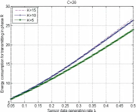
To verify the validity of the model and our analytical expressions obtained in the previous section, we have done some further numerical analysis in this section. The numerical results for a set of specific parameters for this network are presented in this section. The performance measures considered here are several energy consump- tions, package time delay, and the throughput. We as- sume the data storage capacity of the sensor network is 20 (C = 20) and the threshold value K is 5, 10 and 15 respectively. We will observe and compare the effects of various performance measures in the three cases (K = 5, 10 and 15) versa the rate λ of the active sensor node on generating message, and allow the λ changes from 0.05 to 0.5. The other parameters for this sensor network are listed in Table 1.
Figure 2 shows the energy consumption when the sen-
sor node switches from the active mode to the sleep mode. It is clear that the sensor may consume more en- ergy when the generating rate is increase. Also, from this figure, we know that the more the threshold of reserved capacity in a sensor node, the more the energy the sensor node may consume, although the energy assumption does not change too much. Thus, from the viewpoint of minimizing the energy consumption for switching from active mode to sleep mode, it is optimal to minimize the number of data packets which may need relay through the sensor node under investigation. By considering the relay is a vital property for wireless sensor network, it is imperative to find an optimal threshold value of K to leverage the energy consumption.
Figure 3 shows the energy consumption when the sen-
sor node switches from the sleep mode to the active mode. In this case, the energy consumption is not in- creasing with the sensor’s generating rate but decreases a little bit. This is because that the increased generating rate may increase the average staying time of the sensor in state R and N, and reduce the number of the sleep over a unit observation time and then reduce the energy con- sumption of switching from sleep mode to active mode. In addition, this energy consumption is increasing as the threshold of K is increasing. Thus, similar as in the dis- cussion for Figure 1, we also need to find an optimal
threshold value of K to leverage the energy consumption. The curves in Figure 4 and Figure 5 show that with
the increase of the generating rate λ, both the energy as- sumptions in phase N and R will increase because that
Table 1. The specific value of the parameters.
0.2
E
0.51 0.05 0.1 31 μW
tr
e etn11 μW eas0.01 μW esa0.5 μW
Figure 2. Energy consumption for switching from active to sleep mode.
Figure 3. Energy consumption for switching from sleep to active mode.
Figure 5. Energy consumption for transmitting in phase R.
transmitting more package will spend more energy. Also, these energy consumptions are increased as the sensor generates more data.
The average data delay is depicted in Figure 6 when
the sensor generates more data. This delay is obviously increased when either the sensor’s generate rate is in- creased or more relayed message would be processed.
From the Figure 7 on the throughput of the sensor, we
know that the throughput will increase when either the sensor’s generating rate increases or more relayed mes- sage is processed. Based on above analysis, it is clear that a threshold value of K should be identified to lever- age the energy consumption, which is in the list of our research agenda.
5. Conclusions
[image:6.595.311.534.78.259.2]In this paper, we investigated several characteristics of
Figure 6. Average data delay vs the increase of sensor node’s generating rate.
Figure 7. Throughput vs the increase of sensor node’s gen-erating rate.
active/sleep mode in wireless sensor network (WSN). We first derived the steady-state probability distribution when the sensor is in different modes and then provided sensor’s energy consumption measures and performance characteristics. These technical results may have a great intention to the theoretical analysis of various WSNs with consideration of active and sleep features. We note that the analytic result in the research of WSN is impor- tant but often hard to derive. With the analytical method from this paper, we foresee other related results in the future.
6. Acknowledgements
This work was supported in part by NSF under grants CNS-1059116 to Yuhong Zhang and HRD-1137732 to Wei Li, and by AFOSR under grant FA-9550-10-1-0128 to Wei Li.
7. References
[1] J. W. Gardner, V. K. Varadan and O. O. Awadelkarim, “Microsensors, MEMS, and Smart Devices,” John Wiley & Sons, New York, 2001.
[2] A. A. Abbasi and M. Younis, “A Survey on Clustering Algorithms for Wireless Sensor Networks,” Computer Communications, Vol. 30, No. 14-15, 2007, pp. 2826- 2841. doi:10.1016/j.comcom.2007.05.024
[3] I. F. Akyildiz, W. Su, Y. Sankarasubramaniam and E. Cay-irci, “Wireless Sensor networks: A Survey,” Computer Communications, Vol. 38, No. 4, 2002, pp. 393-422. [4] I. F. Akyildiz, T. Melodia and K. R. Chowdhury, “A
Sur-vey on Wireless Multimedia Sensor Networks,” Com- puter Communications,Vol. 51, No. 4, 2007, pp. 921-960. [5] G. Anastasi, M. Conti, M. D. Francesco and A. Passarella,
[image:6.595.58.278.517.694.2]Survey,” Ad Hoc Networks, Vol. 7, No. 3, 2009, pp. 537-568. doi:10.1016/j.adhoc.2008.06.003
[6] P. Baronti, P. Pillai, V. W. C. Chook, S. Chessa, A. Gotta and Y. F. Hu, “Wireless Sensor Networks: A Survey on the State of the Art and the 802.15.4 and ZigBee Stan-dards,” Computer Communications, Vol. 30, No. 7, 2007, pp. 1655-1695. doi:10.1016/j.comcom.2006.12.020
[7] D. Chen and P. K. Varshney, “QoS Support in Wireless Sensor Networks: A Survey,” Proceedings of the 2004 International Conference on Wireless Networks, Las Ve-gas, 21-24 June 2004, pp. 227-233.
[8] K. Sohraby, D. Minoli and T. Znati, “Wireless Sensor Networks: Technology, Protocols, and Applications,” Wiley Publisher, Hoboken, 2007.
[9] J. Yick, B. Mukherjee and D. Ghosal, “Wireless Sensor Network Survey,” Computer Networks, Vol. 52, No. 12, 2008, pp. 2292-2330. doi:10.1016/j.comnet.2008.04.002
[10] S. Tang and W. Li, “QoS Supporting and Optimal Energy Allocation for a Cluster Based Wireless Sensor Network,” Computer Communications, Vol. 29, No. 13-14, 2006, pp. 2569-2577. doi:10.1016/j.comcom.2006.02.007
[11] W. Li, “Several Characteristics of Active/Sleep Model in Wireless Sensor Networks,” Proceedings of the 3rd In- ternational Workshop on Wireless Sensor Networks: The- ory and practice, in conjunction with the 4th IFIP Inter- national Conference on New Technologies, Mobility and Security, Paris, 7-10 February 2011, pp. 1-5.
[12] C. F. Chiasserini and M. Garetto, “An Analytical Model for Wireless Sensor Networks with Sleeping Nodes,” IEEE Transactions on Mobile Computing, Vol. 5, No. 12, 2006, pp. 1706-1718.
[13] C. F. Hsin and M. Liu, “Randomly Duty-Cycled Wireless Sensor Networks: Dynamics of Coverage?” IEEE Trans- actions on Wireless Communications, Vol. 5, No. 11, 2006, pp. 3182-3192. doi:10.1109/TWC.2006.04861
[14] Y. Zhao and J. Wu, “Stochastic Sleep Scheduling for Large Scale Wireless Sensor Networks,” Proceedings of 2005 IEEE International Conference on Communications, Cape Town, 23-27 May 2010, pp. 1-5.
[15] J. Haapola, Z. Shelby, C. A. Pomalaza-Raez and P. Ma-
hoen, “Cross Layer Energy Analysis of Multi-hop Wire- less Sensor Networks,” Proceedings of the European Workshop on Wireless Sensor Networks, Istanbul, 31 January-2 February 2005, pp. 33-44.
[16] W. Li and A. S. Alfa, “A PCS Network with Correlated Arrival Process and Splitted-Rate Channels,” IEEE Journal on Selected Areas in Communications, Vol. 17, No. 7, 1999, pp. 1318-1325. doi:10.1109/49.778188
[17] W. Li and Y. Fang, “Performance Evaluation of Wireless Cellular Networks with Mixed Channel Holding Times,” IEEE Transactions On Wireless Communications, Vol. 7, No. 6, 2008, pp. 2154-2160.
doi:10.1109/TWC.2008.060634
[18] D. P. Gaver, P. A. Jacobs and G. Latouche, “Finite Birth-and death Models in Randomly Changing Envi-ronments,” Advances in Applied Probability, Vol. 16, No. 4, 1984, 715-731. doi:10.2307/1427338
[19] P. Harrison and N. Patel, “Performance Modeling of Communication Networks and Computer Architectures”, Addison-Wesley Longman Publishing Co., Inc. Boston, 1993.
[20] C. F. Chiasserini and M. Garetto, “An Analytical Model for Wireless Sensor Networks with Sleeping Nodes”, IEEE Transactions on Mobile Computing, Vol. 5, No.12, 2006, pp. 1706-1718. doi:10.1109/TMC.2006.175
[21] J. Liu and T. Lee, “A Framework for Performance Model- ing of Wireless Sensor Networks,” Proceedings of 2005 IEEE International Conference on Communica-tions, Seoul Korea, 16-20 May 2005, pp. 1075-1081. [22] X. Chao and W. Li, “Performance Analysis of a Wireless
Network with Multiple Classes of Calls,” IEEE Transac- tions on Communications, Vol. 53, No. 9, 2005, pp. 1542-1550. doi:10.1109/TCOMM.2005.855011
[23] W. Li and X. Chao, “Call Admission Control for an Adap- tive Heterogeneous Multimedia Mobile Network,” IEEE Transactions on Wireless Communications, Vol. 6, No. 2, 2007, pp. 515-525. doi:10.1109/TWC.2006.05192