ISSN Print: 2153-117X
DOI: 10.4236/msa.2019.105029 May 17, 2019 393 Materials Sciences and Applications
Fabrication of Transparent Conducting
Electrode Pattern by Metal Mesh Method on
Stretchable Film Substrate
Gun-Woo Lee
1, Dock Young Lee
2, Byung Chan Lee
3, Kyungha Baek
4,
Genggongwo Shi
5, Jeseob Kim
5, Lee Soon Park
4*, Su Yong Nam
6*1Green Ind. Co. Ltd., Changwon, South Korea 2ELK Corporation, Daejeon, South Korea 3Daegu Technopark, Daegu, South Korea
4School of Materials Science and Engineering, Ulsan National Institute of Science and Technology (UNIST), Ulsan, South Korea 5CCTech Inc., Hwaseong, South Korea
6Department of Graphic Arts Information Engineering, Pukyong National University, Busan, South Korea
Abstract
Smart phones have become one of major electronic devices for human being. The easy and rapid exchange of information between man and machine is carried out by the touch screen panel (TSP) installed in the smart phones. Currently the smart phones are widely spread out while displays for automo-biles are in the initial stage of developments. Since the automobile displays should fit the curved area of indoor space of the vehicle, the TSPs for auto-mobiles need to be fabricated on the flexible and stretchable substrate film. In this study, we selected the thermoplastic polyurethane film as the substrate film and examined the materials and process for fabrication of metal mesh type transparent conducting electrode films suitable for TSPs of automobile displays. The optimum UV resin system was established by the evaluation of various UV resin formulations in the UV imprinting process to make 3 × 3.5 µm trench patterns on the metal mesh type electrode film utilizing the em-bossed metal mask plate. The Ag paste has also been prepared by synthesis of Ag nanoparticles and formulation with the binder polymers. The inlay (fill-ing) of Ag paste in the trench layer of transparent electrode film showed that the variation of electrical resistance was within 10% upon bending up to 100,000 times to radius of 3 mm.
Keywords
Touch Screen Panel, Silver Paste, Stretchable Substrate Film, UV Imprinting, How to cite this paper: Lee, G.-W., Lee,
D.Y., Lee, B.C., Baek, K., Shi, G., Kim, J., Park, L.S. and Nam, S.Y. (2019) Fabrication of Transparent Conducting Electrode Pat-tern by Metal Mesh Method on Stretchable Film Substrate. Materials Sciences and Applications, 10, 393-405.
https://doi.org/10.4236/msa.2019.105029
Received: March 29, 2019 Accepted: May 14, 2019 Published: May 17, 2019
Copyright © 2019 by author(s) and Scientific Research Publishing Inc. This work is licensed under the Creative Commons Attribution International License (CC BY 4.0).
DOI:10.4236/msa.2019.105029 394 Materials Sciences and Applications UV Resin Formulation
1. Introduction
The automobile displays are becoming an important part of display devices ow-ing to the connected car issue as shown in recent consumer electronics show (CES) and mobile world congress (MWC). Some luxury cars have multiple dis-plays including central information display (CID), rear seat entertainment and head-up displays [1][2]. Among these, CID is the key display for automobile industry. The touch screen panel (TSP) is widely employed in the CID and its size is gradually increasing [3]. In this study a 12-inch TSP has been fabricated utilizing a flexible and stretchable substrate film. As the size of TSP increases, the indium tin oxide (ITO) film should be replaced with a metal mesh type con-ducting electrode film due to the high electrical resistance of ITO film [4]. We selected thermoplastic polyurethane film as the substrate film of flexible TSP since the fabrication of TSP module requires curved surface to fit in the CID panel of the automobile. Although the TSPs fabricated on the rigid transparent film like polyethyleneterephthate (PET) films have been widely used, those on transparent flexible and stretchable films have not been reported in depth, espe-cially for automobile displays [5][6]. The formulation of photosensitive UV re-sin and silver paste are key materials for the low electrical resistance and high transparency of the TSP for automobile application. The preparation of the two important materials and the application processes have been examined.
2. Experiments
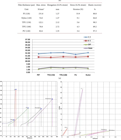
The transparent films tested as substrate for metal mesh type conducting elec-trode films include polyimide (PI-100), thermoplastic polyurethane (TPU-100 and TPU-150), another polyurethane (PU-100) and nylon (Nylon-100), obtained from Kolon Industries, Korea. The UV oligomer and monomers for formulation of photosensitive UV resins are shown in Figure 3, obtained from CCTech. Co., Korea. The binder polymers for the preparation of silver pastes were as follow-ing: polyurethane (Ebecryl 8411, Allnex, Sydney, Australia), Mw = 1000;
Polyest-er-1 (ES-365, SK Chemical Co., Korea), Mw = 40,000, Tg = 16˚C; Polyester-2
(ES-215, SK Chemical Co., Korea), Mw = 35,000, Tg = −10˚C; Epoxy resin
(KDN-255, Kukdo Chemical Co., Korea), Mw ≤ 3000, EEW = 450 - 500.
DOI: 10.4236/msa.2019.105029 395 Materials Sciences and Applications In order to make a TSP for automobile application a metal mesh type trode film should be fabricated. The process of imprinting the mesh type elec-trode pattern, UV exposure equipment and schematic diagram of the elecelec-trode pattern layer on substrate film are shown in Figures 1(a)-(c), respectively. The photosensitive UV resin is coated on the embossed metal mold and a flexible TPU film is placed on top of the mold. Then a transparent glass is put on the TPU film, followed by rolling of UV resin, UV exposure and demolding.
3. Result and Discussion
3.1. Substrate Films and Properties
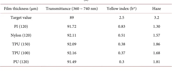
[image:3.595.163.512.438.541.2]The mechanical and optical properties of the substrate films are important sub-ject of TSP for application to automobile industry. We have chosen five different transparent films including polyimide (PI-100) film, thermoplastic polyurethane films (TPU-100 and TPU-150 the numbers indicate thickness of the film in μm), another polyurethane film (PU-100) and nylon (Nylon-100) film as candidates. The optical properties of the five films are shown in Figure 2 and Table 1. The optical properties of the five films were similar and all films satisfied the specifications for
[image:3.595.206.539.595.732.2]Figure 1. UV imprinting process of mesh type electrode pattern on the TPU film.
Table 1. The optical (a) and mechanical properties (b) of substrate films.
(a)
Film thickness (µm) Transmittance (360 ~ 740 nm) Yellow index (b*) Haze
Target value 89 2.5 3.2
PI (120) 91.72 0.83 1.30
Nylon (120) 92.11 0.51 1.57
TPU (150) 92.09 0.38 1.86
TPU (100) 92.16 0.37 1.68
DOI:10.4236/msa.2019.105029 396 Materials Sciences and Applications (b)
Film thickness (µm) Max. stress Elongation (0.2% strain) Stress (0.2% strain) Elastic recovery
Unit N/mm2 mm Newton (N) %
PI (120) 231.8 1.27 53.9 80.8
Nylon (120) 74.0 1.27 9.1 84.8
TPU (150) 122.1 2.12 5.6 98.5
TPU (100) 78.8 2.72 4.3 89.2
PU (120) 82.6 1.35 3.4 97.3
(a)
[image:4.595.63.538.75.625.2](b)
Figure 2. The optical (a) and mechanical property (b) curves of substrate films.
use in TSP fabrication.
The mechanical properties of the films were quite different as shown in
Fig-ure 2(b) and Table 1. Although the mechanical strength of the Nylon and PI
DOI: 10.4236/msa.2019.105029 397 Materials Sciences and Applications TPU films were better than those of the Nylon and PI films. The TPU-150 film was chosen as the substrate film for flexible and stretchable TSP since it had both high elastomeric recovery (98.6%) and high Young’s modules of 5.63, suitable for the in-mold fabrication process of automobile TSPs.
3.2. UV Resin Formulation and Properties
The formulation of UV resin is important in the UV imprinting process due to two reasons. First the UV resin affects the demolding of the substrate film on which fine mesh electrode patterns were formed after UV curing off the em-bossed metal mold.
Second, the optical and mechanical properties of the substrate film with UV imprinted electrode pattern layer are also dependent on the formulation of pho-tosensitive UV resin. The structures of UV monomers used in the formulation are shown in Figure 3.
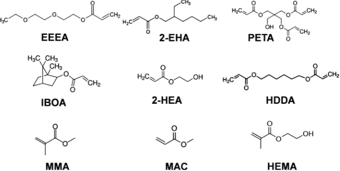
In order to check the basic demolding and optical properties of the mesh elec-trode patterned film, a simple UV resin formulation was prepared which were composed of F-150 polyurethane oligomer, IBOA, 2-EHA and PI-TPO photoi-nitiator dissolved in 2-HEMA monomer (25 wt%) as shown in Table 2(a). Here F-150 UV oligomer was included to have a good adhesion to the TPU-150 sub-strate film. IBOA and 2-EHA monomers were employed to achieve the balance of hard and soft monomers which affect he demolding of electrode patterned TPU film off the metal mold. The test films were obtained in three different ways 1) UV resin only, 2) unpatterned UV resin layer/TPU film and 3) patterned UV resin layer/TPU film by using UV imprinting method as shown in Table 2(b).
From Table 2(b) the two-layer film fabricated with UV imprinted electrode pattern on substrate film exhibited improved optical property compared to the film made with flat (without pattern) UV resin layer on TPU film, especially the optical properties like haze and b* value. This may be due to the index matching effect of two-layer film and interference of light in the patterned two-layer film.
[image:5.595.197.539.534.706.2]After confirming that the two-layer films consisted of patterned mesh electrode
DOI:10.4236/msa.2019.105029 398 Materials Sciences and Applications layer on TPU-150 substrate film have good optical property for touch panel use, the mechanical and other process properties of the composite film were ex-amined. Several issues are involved in the relationship among the UV resin for-mulation and mechanical/process properties of the two-layer film. The im-provements of UV resin formulation are explained in Table 3.
Table 2. UV resin formulation (a) and optical properties of films (b) made with 1) UV
resin only 2) Unpatterned UV resin layer/TPU film and 3) patterned UV resin layer/TPU film.
(a)
Sample
UV oligomer UV monomer Photoinitiator
Total (%)
F130 IBOA 2-EHA PI-TPO
(25 wt%, 2-HEMA)
UVX-3 60 35 5 100
UVX-4 50 45 5 100
UVX-5 50 15 30 5 100
(b)
Optical Properties Transmittance b* Haze
Target value 89.0 3.20 2.50
Preparation of films for examination of optical properties:
1) Film made with UV resin only 2) Unpatterned UV resin layer/TPU film 3) Patterned UV resin layer/TPU film
UVX-3 (1) 93.2 2.63 2.83
UVX-3 (2) 92.7 1.93 2.08
UVX-3 (3) 92.6 1.99 2.15
UVX-4 (1) 93.2 4.88 5.23
UVX-4 (2) 92.8 2.23 2.41
UVX-4 (3) 92.8 1.92 2.07
UVX-5 (1) 93.5 4.44 4.74
UVX-5 (2) 92.6 2.60 2.90
UVX-5 (3) 92.7 2.26 2.44
Table 3. The improvement of UV resin formulation for mesh electrode imprinting.
Sample Improvement of UV resin formulation
UV oligomer UV monomer Photoinitiator
Total (%)
F150 EEEA MMA MAC PETA IBOA HDDA 2-HEA 2-EHA PI-TPO
(25wt% in 2-HEA) UVX-6 a) Adhesion,
stretchability 50 35 10 5 100
UVX-7 40 15 15 5 20 5 100
UVX-8 20 15 25 5 30 5 100
UVX-9 b) Stickiness, bad smell, demolding
40 20 10 5 20 5 100
UVX-10 40 5 10 15 20 10 100
[image:6.595.58.546.558.722.2]DOI: 10.4236/msa.2019.105029 399 Materials Sciences and Applications In UVX-6, 7, 8 resin formulations, the adhesion of electrode mesh layer on the substrate film was good enough upto 200% elongation of the double layer film. But the stickiness of the surface of electrode mesh layer was too high after UV curing. This was due to the high amount of soft monomers (sum of EEEA and 2-EHA monomers) which was in the range of 35 wt% to 45 wt%. So we included a hard monomer, methylmethacrylate (MMA) as shown in UVX-9, but the UV resin containing MMA was found not to be cured by UV exposure upto 150 mJ. This may be due to the steric hindrance effect of methyl group in the MMA monomer during the UV curing process. When the MMA monomer was re-placed with methylacrylate (MAC) (UVX-10), the UV curing was found to pro-ceed under a normal UV dose of 100 mJ. However, the adoption of MAC mo-nomer in the UV formulation caused the environmental problem of bad smell. So we reformulated the UV resin without MAC monomer as shown in UVX-11.
The next important task of UV resin formulation was to solve the clean de-molding of the two-layer film off the embossed metal mold after UV curving process. The UV resin formulations for this purpose are shown in Table 4. The UV formulation (UVX-11) exhibited good electrode pattern with dimension of 5 × 5.5 (width × depth) µm. When we used the UVX-11 resin formulation to pat-tern the mesh electrode layer with dimension of 3 × 3.5 µm, the electrode patpat-tern after demolding showed some defect as shown in Figure 4.
[image:7.595.60.538.429.700.2]The difficulty of demolding 3 × 3.5 µm mesh electrode layer on TPU double layer film off the embossed metal mold seemed to be due to the increased interfacial
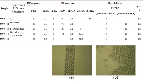
Table 4. UV resin formulations for improving the demolding of the metal mold with the electrode pattern size of 3 × 3.5 µm.
Sample Improvement of UV resin formulation
UV oligomer UV monomer Photoinitiator
Total (%)
F150 EEEA PETA IBOA HDDA 2-HEA 2-EHA PI-TPO
(25wt% in 2-HEA) (25wt% in EEEA) UVX-11 a) UV
exposure 15 2.5 5 37.5 20 10 10 100
UVX-12 20 7.5 5 27.5 20 10 10 100
UVX-13 b) Demolding (trench size; 3 × 3.5 µm)
20 7.5 5 22.5 20 5 10 10 100
UVX-14 20 7.5 5 10 20 17.5 10 10 100
UVX-15 20 7.5 5 25 22.5 10 10 100
Figure 4. The engraved electrode pattern (a) narrow bezel part (b) wide bezel part
DOI:10.4236/msa.2019.105029 400 Materials Sciences and Applications surface area between the patterned electrode layer and the fine metal mold.
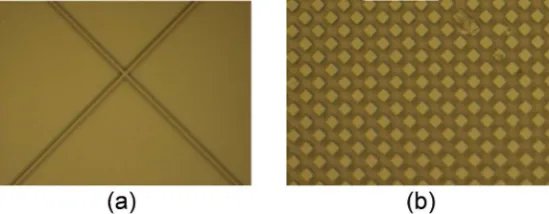
So we first increased the amount of the photoinitiator as shown in UV resin for-mulation in UVX-12. The demolding of the two-layer film became easier as the amount of photoinitiator was increased, but the complete demolding of clean two-layer film off the metal mold was not achieved. This seemed to be caused by higher amount of hard UV monomer, IBOA in the formulation. So we replaced part of the IBOA hard monomer with neutral monomer 2-hydroethylacrylate (2-HEA) while keeping the amount of the soft monomer (EEEA) 15 wt% constant. When the amount of IBOA hard monomer was decreased to 10 wt%, the demolding of the two-layer film off the metal mold became clean and complete as shown in Figure 5.
We further improved the UV formulation (UVX-15) by completely removing IBOA monomer and increasing the amount of HDDA cross-linking monomer to 25 wt%. The increase of the photoinitiator and HDDA crosslinking monomer could lead to the complete participation of diacrylate monomers in the cros-slinking reaction thus increasing the strength of the double layer film during the demolding process.
3.3. Ag Paste, Inlay and Electrode Performance
After establishing the optimum condition for patterning of trench type mesh electrodes, the formulation of Ag paste and its inlay (filling) into electrode trench (3 µm width) and the properties of the completed transparent conducting electrode film were examined.
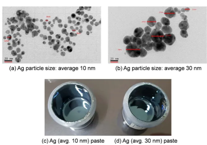
First silver nanopowder was synthesized by using aliphatic amine, carboxylic acid as source of surfactant, silver acetate as precursor of Ag nanoparticle and hydrazine as reducing agent of silver ion. After synthesis of the Ag nanoparticles the product suspension was washed with 2-(2-ethoxyethoxy)ethyl acetate (ECA) solvent, and then separated by centrifuge to obtain Ag nanoparticles in a powder form. The TEM images of Ag nanoparticles (a, b) and the Ag pastes (c, d) made with the Ag nanoparticles are shown in Figure 6.
[image:8.595.236.511.586.693.2]The Ag nanoparticles were used to prepare stretchable Ag paste samples by using three different binder polymers (polyurethane, polyester, epoxy resin) and BYK dispersant in ECA/r-butyrolactone (r-BTL) = 50:50 wt% mixture solvent as shown in Table 5.
Figure 5. The engraved electrode pattern (a) sensor part and (b) bezel part of electrode
DOI: 10.4236/msa.2019.105029 401 Materials Sciences and Applications
Figure 6. TEM images of Ag nanoparticles and camera images of Ag pastes.
Table 5. Formulation of Ag paste for selection of binder polymer.1
Ag Ink Ag nanoparticles Binder polymer2 Solvent Additive
Ag (10 nm) Ag (30 nm) ECA/r-BTL3 = 50/50 BYK-1804
AgP-1 8.8 70.2 Polyurethane: 4.0 16.0 1.0
AgP-2 8.8 70.2 Polyester-1: 4.0 16.0 1.0
AgP-3 8.8 70.2 Polyester-2: 4.0 16.0 1.0
AgP-4 8.8 79.2 Epoxy resin: 4.0 7.0 1.0
1Formulation of Ag paste is based on wt%. 2Binder polymers: polyurethane (Ebecvyl 8411, Allnex, Sydney,
Australia), Mw = 1,000; Polyester-1 (ES-365, SK Chemical Co., Korea), Mw = 40,000, Tg = 16˚C; Polyester-2
(ES-215, SK Chemical Co., Korea), Mw = 35,000, Tg = −10˚C; Epoxy resin (KDN-255, Kukdo Chemical Co.,
Korea), Mw ≤ 3000, EEW = 450 - 500. 3Solvent: r-BTL (r-butylzolactone). 4Additive: BYK-180 (BYK Co.,
Germany).
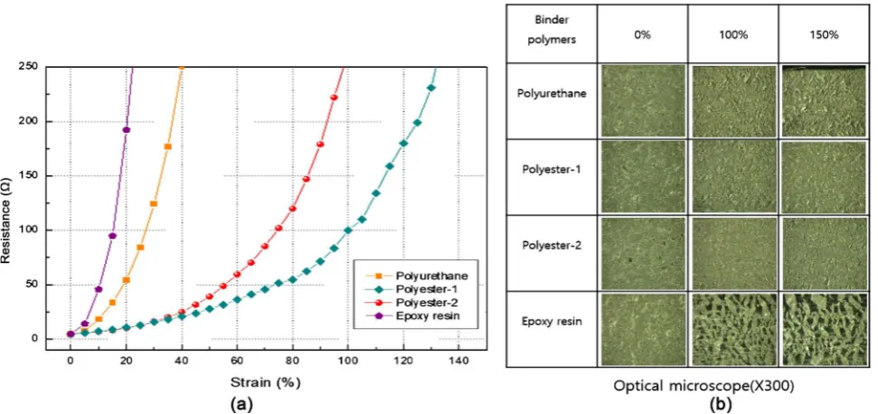
[image:9.595.208.540.343.445.2]DOI:10.4236/msa.2019.105029 402 Materials Sciences and Applications over 100% strain while Ag pastes with polyester binders showed no cracks upto 150% strain (Figure 7(b)) [8].
The Ag paste with polyester-1 binder polymer (AgP-2) showed wider strain range than AgP-3 paste with polyester-2 from Figure 7. However, the adhesion of Ag paste with polyester-2 binder polymer (AgP-3) to the substrate film was better than that of Ag paste with polyester-1 binder, thus polyester-2 was se-lected as binder polymer of Ag paste.
[image:10.595.58.544.321.550.2]Having selected the polyester-2 as binder polymer we further modified the formulation of Ag pastes for the low electrical resistance and good adhesion to mesh electrode layer. The good adhesion of Ag paste to the trench layer made of UVX-15 resin is important because the depth of Ag paste filled in the trench layer is less than 3.5 µm which is labile to the strain deformation. The modifica-tion of Ag pastes is shown in Table 6. Here the Ag pastes (Ag T-1 and Ag T-2) showed lower electrical resistance than Ag T-3 paste. The electrical resistance usually decreases with the increasing Ag nanoparticles and decreasing binder polymer which is a non-conductor. It was noted that the effect of decreasing the
Figure 7. The surface resistance vs. strain curves (a) and optical microscope images (b) of the screen printed Ag pastes made with
formulations in Table 5.
Table 6. Silver paste formulations and evaluation for low electrical resistance and high adhesion to the trench layer surface.
Ag Ink Pastes*
Ag nanoparticles
Binder Polymer: Polyester-2
Solvent Additive Evaluation
Ag (d = 10 µm) Ag (d = 20 µm) ECA/r-BTL = 50/50 BYK-180 Electrical Resistance (Ω/square) Adhesion
Ag T-1 8.8 70.2 2.0 18 1.0 4-5 X
Ag T-2 8.8 70.2 3.0 7 1.0 4-5 O
Ag T-3 8.8 79.2 4.0 7 1.0 8-10 O
[image:10.595.57.540.611.707.2]DOI: 10.4236/msa.2019.105029 403 Materials Sciences and Applications binder polymer was stronger than increasing the Ag nanoparticles from Table 6. The comparison between AgT-1 and AgT-2 pastes also indicated that there is a limit to the decrease of binder polymer which could not guarantee the adhesion to the trench layer surface.
After optimizing the Ag paste formulation for inlay (filling) into the trench layer, the Ag paste (AgT-2) was filled in the trench layer by using scratching machine. Figure 8 shows that the Ag paste was filled well in the trench layer both in the sensor part and bezel part.
The variation of electrical resistance of the Ag paste (AgT-2) filled electrode film upon bending to 3 mm radius upto 100,000 times was 8.8% (the specifica-tion 10.0%) as shown in Figure 9.
[image:11.595.261.484.275.471.2]This basic research on the materials and process of metal mesh type TSP fa-brication will be a sound foundation for use in the automobile display industry.
Figure 8. The SEM images of empty trench layer pattern (a) and filling (inlay) of Ag paste
in the trench layer (b).
Figure 9. Bending test equipment and the variation of electrical resistance of Ag paste filled electrode film after 100,000 times, 3
[image:11.595.59.536.513.692.2]DOI:10.4236/msa.2019.105029 404 Materials Sciences and Applications
4. Conclusion
Touch screen panels (TSPs) for automobile application require a flexible and stretchable substrate film. In this work a thermoplastic polyurethane film was selected as a substrate film for fabrication of mesh type electrode patterns by us-ing photosensitive UV resin. In the mesh electrode patternus-ing the balance of hard and soft monomer in addition to the balance of multifunctional monomer and monofunctional monomer were found important for the optical and me-chanical properties of UV resin formulation, especially the demolding process after UV curing off the finely patterned metal mold. It was also noted that the formulation of silver pastes is very important for the inlay process and balance between the low electrical resistance and bending test up to 100,000 times with radius of 3 mm. The nano-sized silver particles were found to give the low elec-trical resistance of 4 - 5 Ω/square in combination with the polyester binder po-lymer with high molecular weight (Mw = 35,000 g/mol) and low glass transition temperature (Tg = 16˚C).
Acknowledgements
This material is based upon work supported by the Ministry of Trade, Industry & Energy (MOTIE, Korea) under Industrial Technology Innovation Program “Development of Stretchable Transparent Electrode Film with 3 μm Line Space Based on Cu/Ag Composite Nanoparticles” (No. 10062220).
Conflicts of Interest
The authors declare no conflicts of interest regarding the publication of this paper.
References
[1] Sun, M. and Yu, H. (2019) Automobile Intelligent Dashboard Design Based on Human Computer Interaction. International Journal of Performability Engineering, 15, 571-578. https://doi.org/10.23940/ijpe.19.02.p21.571578
[2] Qiu, C., Liu, Z., Wang, K. and Sun, X. (2018) 34.1: Invited Paper: Application of Display Technology in Automobile. Society for Information Display, 49, 364-366. https://doi.org/10.1002/sdtp.12728
[3] Haga, H., Sugimoto, D., Yang, Y., Sasaki, H., Asai, T. and Shigemura, K. (2019) Ca-pacitive Touchscreen-Integrated Electrostatic Tactile Display with Localized Sensa-tion. Society for Information Display, 27, 59-71. https://doi.org/10.1002/jsid.748 [4] Hamasha, M.M., Dhakal, T., Alzoubi, K., Albahri, S., Qasaimeh, A., Lu, S. and
Westgate, C.R. (2012) Stability of ITO Thin Film on Flexible Substrate under Thermal Aging and Thermal Cycling Conditions. Journal of Display Technology, 8, 385-390. https://doi.org/10.1109/JDT.2011.2176532
[5] Choi, Y.-M., Kim, K.-Y., Lee, E., Jo, J. and Lee, T.-M. (2015) Fabrication of a Sin-gle-Layer Metal-Mesh Touchscreen Sensor Using Reverse-Offset Printing. Journal of Information Display, 16, 37-41. https://doi.org/10.1080/15980316.2014.991770 [6] Kim, K., Hyun, B.G., Jang, J., Cho, E., Park, Y.-G. and Park, J.-U. (2016)
Dis-DOI: 10.4236/msa.2019.105029 405 Materials Sciences and Applications play, 17, 131-141. https://doi.org/10.1080/15980316.2016.1240111
[7] Nam, H.M., Seo, D.M., Yun, H.D., Thangavel, G., Park, L.S. and Nam, S.Y. (2017) Transparent Conducting Film Fabricated by Metal Mesh Method with Ag and Cu@Ag Mixture Nanoparticle Pastes. Metals, 7, 176.
https://doi.org/10.3390/met7050176