1876-6102 © 2017 The Authors. Published by Elsevier Ltd. This is an open access article under the CC BY-NC-ND license (http://creativecommons.org/licenses/by-nc-nd/4.0/).
Peer-review under responsibility of the organizing committee of the 1st International Conference on Energy and Power. doi: 10.1016/j.egypro.2017.03.186
Energy Procedia 110 ( 2017 ) 567 – 573
ScienceDirect
1st International Conference on Energy and Power, ICEP2016, 14-16 December 2016, RMIT
University, Melbourne, Australia
Bionic inspired study of heat pipe from plant water migration
Jiaju Hong
a, Sheng Liu
a,c, Yuying Yan
a,b,*
aFluids & Thermal Engineering Group, Faculty of Engineering, University of Nottingham, Nottingham, NG7 2RD, UK bFluids & Thermal Engineering Research Centre, University of Nottingham Ningbo, China
cCollege of Mechanical and Electrical Engineering, Hohai University, Changzhou, 213022, China
Abstract
Heat pipe is well regarded as super thermal conductor and has a wide range of applications in the variety of industry sections. A great number of researches have been done on enhancing the performance of heat pipe through improving the flow pattern. The research on plant water migration based on bionic engineering approach provides a very interesting path to the fluid flow enhancement inside heat pipe, and improvement of inner structure as well. The main forces that drive the water migrates in plants are capillary effect, friction, gravity and transpiration effect, and which are also the main driven forces in heat pipe. Although most researches on heat pipe focus on capillary effect against gravity, transpiration effect is still very important as dragging force occurs when water evaporates. And all these can be investigated through plant water migration. A mathematical model describing the water migration process in plant is proposed in this paper. And the result obtained from mathematical calculation is compared with the experimental measured result using Nuclear Magnetic Resonance (NMR) technology. The perfect matching between the two results confirmed the possibility of using the mathematical model to analyze fluid flow in micro channels, including heat pipe. And it also successfully put transpiration effect and friction into consideration, which give out a clearer view of the forces inside heat pipe for further research.
© 2017 The Authors. Published by Elsevier Ltd.
Peer-review under responsibility of the organizing committee of the 1st International Conference on Energy and Power.
Keywords: bionic engineering; plant water migration; NMR
* Corresponding author. Tel.: +44(0)1159513168; fax: +44(0)1159513159.
E-mail address: [email protected]
© 2017 The Authors. Published by Elsevier Ltd. This is an open access article under the CC BY-NC-ND license (http://creativecommons.org/licenses/by-nc-nd/4.0/).
Nomenclature
p pressure
γ viscosity
θ contact angle
r radius
ρ density
g gravity
h height
E evaporation flux density
A surface area
Kh hydraulic conductivity
f friction factor
w width of helical structure in xylem d gap between helical structures
ε gap between simplified roughness
δ width of simplified roughness t height of simplified roughness
1.Introduction
Heat pipe is well regarded as super thermal conductor and has a wide range of applications in the variety of industry sections. It has already become an important heat transfer device in industry. A series of researches have been carried out to improve the heat pipe performance, especially the capillary heat pipes.
Capillary heat pipe is a typical widely used heat pipe. Many forces are involved to drive the fluid flows through the wick structure in capillary heat pipe. These forces on fluid are very complicated, in a manufactured micro channel like capillary heat pipe, as the wick structure can be seen as porous media. Capillary effect occurs in the process of moving the agent from cold end to hot end, and gravity may apply as well. At the hot end, an additional driving force may take place when water evaporates, even though most researchers don’t consider it as contributing. Friction is a significant force affecting the flow as well. For capillary heat pipe improvement, a change in wick structure can help generate effective results.[1]
Water transports in plants from root to leaf through the vascular system, xylem and phloem. Xylem and phloem are formed by a brunch of dead-cell rings, in vast number of shapes, through evolution. Xylem is believed to be the conduit in which water moves upward from root to leaf, while phloem is the one in which nutrients moves downward. The inner structure of xylem is similar to the wick structure in capillary heat pipe. Therefore, the research on the water migration process may contribute to detect the water flow behaviours in capillary heat pipe. The bionic study of the relationship between plant and water is called Hydraulic Architecture (HA) , which is firstly proposed by Zimmerman in 1978[2].
Xylem conduits can be simplified as a microscale conduit, with the surface of xylem wall affecting the contact angle of water just like the wetting of wick structure. And all the forces discussed in heat pipe would happen as well in nature, especially woody plants, as water moves upward from root to leaf with the contribution of capillary effect against gravity and friction, and then vaporized into air by transpiration effect. Therefore, studying the natural phenomenon could support the enhancement of heat pipe performance.
2.Mathematical Model
2.1 Cohesion & tension theory
by Milburn.[4] The sap or water migrates in the xylem is due to the effects of a series of forces, the negative pressure and tension within water takes water up, while the cohesion force keeps water continuous, according to C-T theory.
Following assumptions are adopted in the C-T theory. The liquid water in plant xylem system is treated as a continuous single phase flow, while the narrow conduit wall could enable evaporation from transpiration, but resist the entry of air at the same time. And water is closely contacted to the conduit wall because of the cohesion of water molecules and tension with the wall. In C-T theory, the main forces that involved in water migration in xylem are capillary effect, root pressure (osmosis effect), transpiration effect and friction.
1.2 Forces involved in plant xylem
The xylem conduit is treated as a capillary tube in most researches. Capillary effect and gravity are thought to be the two main forces that induce the water migration in xylem, based on this assumption. The commonly used equation for capillary force is as follow,
2
cos
c
p
r
J
T
(1)
And gravity would be simply written as,
g
p
U
gh
(2)For most plants, the diameter of xylem system is in the range of 10 to 100μm. It can be found out that smallest diameter has the highest the capillary effect from equation (1). The water can only be lift up to 3m height under the effect of capillary effect even with the smallest diameter of xylem. So, it can be concluded that the capillary force is a big contributing force in water migration in xylem, but not the most important one, especially for those tall plants over 10 metres in height.
Transpiration effect is induced by water evaporation in plants, mainly in leaves. This is widely believed to be the critical mechanism for long distance water transportation in xylem system, especially in tall trees of over ten metres height. As water evaporates, negative pressure appears in xylem, and forces water to move up with the cohesion and tension within water molecules. [5]
The water evaporation is closely related to many inner or outer factors including weather condition, height, and plant type etc. It is quite hard to propose a simplification model to describe transpiration effect in plant, no mention to propose a mathematical model for transpiration effect considering all the factors. The most famous solution is proposed by Van den Honert in 1948.[6] The water flow in xylem is considered as an analogue of the Ohm’s Law. This means the pressure gradient is linear along the xylem, and the pressure is linked to the water flux in evaporation, together with a parameter, hydraulic conductivity as the resistance in Ohm’s Law.
dP dx
x/
EA K
/
h (3)
P
xU
Qh
/
K
h (4)where, E is evaporation flux density, while A is the surface of leaves, Kh is the hydraulic conductivity.
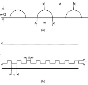
The inner structure of xylem is helical structure in capillary conduit, with resistance higher than ideal, as can be seen in Fig.1. So, the xylem conduit can be considered as a cylinder with helical structure on the boundary, with radius r, or diameter d, and height h. And when analyzing the friction force, the xylem wall structure can be simplified as below in Fig. 2. The structure in Fig. 2(a) then is simplified to Fig. 2(b) based on the same hydraulic diameter, and then the relationship among these parameters of xylem wall structure can be written as,
G
H
d
(5)w
4
S
G
2
4
w
t
S
(7)
The friction factor of xylem wall could be determined from the details of the xylem structure, when using the Darcy-Weibach Equation to calculate the pressure loss in the water migration process due to friction.The friction factor is taken out as a parameter, so the pressure loss due to friction can be written,
2
2u
d
h
f
h
p
fU
fU
(8)where, ρ is sap density, f is friction factor, h is height, d is diameter of xylem conduit, and u is flow velocity. The friction factor f can be calculated as,
Re
16
f
(9) [image:4.544.80.454.275.401.2]The forces analysed above are main forces that contribute to the water migration in plant xylem. Even though there are still some other minor forces, such as the root pressure, which have been ignored for the influences of those forces are quite small.
Fig 1. microscope image of xylem inner structure
[image:4.544.188.342.441.589.2]1.3 Mathematical model
The main forces that contribute to the sap rising from root to leaf through xylem in plants are capillary effect, transpiration effect, friction and gravity. So the overall equation can be written as,
p
fp
cp
gp
t0
(10) where, friction force pf, capillary force pc, gravity pg and transpiration force pt add together should be equilibrium. And after putting the previous analysis into Eq. 10, the mathematical model should be,
2
cos
0
2
2
h
K
Qh
gh
r
u
d
h
f
J
T
U
U
U
(11)The parameters in equation (11) can be measured or calculated with empirical equations, and then the mean velocity in xylem can be obtained with the equation.
3.Comparison and Discussion
The fluid flow in xylem is very complicated in real plants. Some water may be absorbed by plant cell, and some water penetrates outward into other conduits or inward from other conduits for water can flow through the xylem walls during the water migration in xylem. However, the water that flows through conduit walls is relative small compare to the water flows in the xylem. And also the amount of water absorbed by plant cell is very small compared to the water that vaporized at leaves. So the xylem conduit is considered as a solid wall tube without water loss in this paper. Also there are a lot of xylem conduits in a plant, and the diameters of xylem conduits are in a quite large range, the mean diameter is adopted in the research.
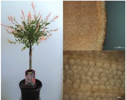
A particular plant Salix Integra Flamingo, a woody plant is measured with NMR in the research. The radius of xylem conduits of Flamingo is measured with microscope, as can be seen in Fig. 3. The upper image shows the cross section of the stem, with outermost parts barks of the stem and inner part the regular xylems, which is the small circular
shapes in the lower image, with a diameter of around 10μm. So, 10μm is adopted as the mean diameter of xylem
conduit in the following calculations.
[image:5.544.175.381.419.583.2]Then the parameters in Eq. 11 can be obtained or calculated based on the literatures [7-14], according to the specific species of the plant and the mean diameter of xylem conduits. And the average velocity obtained from Eq. 11 for the Salix Integra Flamingo is 0.13mm/s.
Fig 3. Image of Salix Integra Flamingo and stem under microscope.
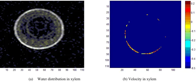
For the plant put into NMR for scanning is alive, and the velocity of flow inside xylem can be measured in situ, shown in Fig. 4(b). NMR can measure the velocity in one direction. And it is believed that the water flow within xylem conduits is extremely few and slow, and that water in plant stem flows within the xylem in the same direction, from root to leaf. The velocity of water flow in plant stem is measured, and then comparing with the previous image of the water distribution in stem in Fig. 4(a). And by putting the two images together, the velocity which falls on the same pixels with higher water distributions would be the real velocity of flow in plants. The mean velocity of the cross section measured by NMR is 0.11mm/s.
[image:6.544.77.466.151.314.2](a) Water distribution in xylem (b) Velocity in xylem
Fig 4. Flow velocity in plant xylem by NMR
The average velocity measured by NMR is 0.11mm/s, while the calculated velocity from mathematical model is 0.13mm/s. The difference between the calculation velocity and the experiment velocity is only 0.02mm/s, with a relative error 18.2%. And this strongly proved the accuracy of the mathematical model, and the potential for the model to be adapted into further fields in engineering, such as micro-channel flow and heat pipes.
4.Conclusion
In this paper, a novel mathematical model is proposed to describe the water migration process in plant xylem conduits. All forces are quantized and written in the form of pressure, including capillary force, gravity, transpiration effect and friction. The inner structure of xylem conduit is measured and simplified to calculate the friction factor.
To verify the mathematical model, a NMR experiment is carried out to compare with the result calculated from the mathematical model. And the two values match very well, indicating the model has quite a high accuracy. Further improvement on this model is needed, however, it is already showing the potential of using the mathematical model in heat transfer devices such as heat pipe, which contains fluid flow through micro channel and evaporation, exactly the same process happens in plants. Therefore, the next step of the presented work will be enhancing the heat pipe performance through analysing the flow pattern in wick structure using the mathematical model.
Acknowledgements
The project is partially supported by Ningbo Science and Technology Bureau Technology Innovation Team project under Grant No. 2016B10010, and Ningbo International Cooperation Program under Grant No. 2015D10018, and also RIPED Petro China research Grant.
References
[3] Dixon, H.H. and J. Joly, On the ascent of sap. Philosophical Transactions of the Royal Society of London. B, 1895: p. 563-576. [4] Milburn, J.A., Water flow in plants. 1979: Longman Inc.
[5] Denny, M., Tree hydraulics:how sap rises.European Journal of Physics, 2012. 33(1): p. 43.
[6] Van den Honert, T., Water transport in plants as a catenary process. Discussions of the Faraday Society, 1948. 3: p. 146-153.
[7] JEJE, A.Y.A. and M.H. ZIMMERMANN, Resistance to Water Flow in Xylem Vessels. Journal of Experimental Botany, 1979. 30(4): p. 817-827.
[8] Tyree, M.T., The cohesion-tension theory of sap ascent: current controversies. Journal of Experimental Botany, 1997. 48(10): p. 1753-1765. [9]Kohonen, M.M. and Å. Helland, On the function of wall sculpturing in xylem conduits. Journal of Bionic Engineering, 2009. 6(4): p. 324-329. [10] Holbrook, N.M. and M.A. Zwieniecki, Transporting water to the tops of trees. Physics Today, 2008. 61(1): p. 76-77.
[11] Giordano, R., et al., Flow in xylem vessels and Poiseuille's law. Canadian Journal of Botany, 1978. 56(3): p. 333-338. [12] Siau, J.F., Permeability. 1984: Springer.
[13 Calkin, H., A. Gibson, and P. Nobel, Biophysical model of xylem conductance in tracheids of the fern Pteris vittata. Journal of Experimental Botany, 1986. 37(7): p. 1054-1064.