Hyper-damping properties of a sti
ff
and stable linear oscillator with a negative sti
ff
ness
element
I. Antoniadisa, D. Chronopoulosb, V. Spitasa, D. Koulocherisa
aMachine Design and Control Systems Section, School of Mechanical Engineering, National Technical University of Athens, Greece bDivision of Materials, Mechanics and Structures, University Park, The University of Nottingham, NG7 2RD, UK
Abstract
A simple, stiff, statically and dynamically stable linear oscillator incorporating a negative stiffness element is used as a template to provide a generic theoretical basis for a novel vibration damping and isolation concept. This oscillator is designed to present the same overall static stiffness, the same mass and to use the same damping element as a reference classical linear SDoF oscillator. Thus, no increase of the structure mass or the viscous damping is needed, as in the case of a traditional linear isolator, no decrease of the overall structure stiffness is required as in the case of ’zero-stiffness’ oscillators with embedded negative stiffness elements. The difference from these two templates consists entirely in the proper redistribution and reallocation of the stiffness and the damping elements of the system. Once such an oscillator is optimally designed, it is shown to exhibit an extraordinary apparent damping ratio, which is even several orders of magnitude higher than that of the original SDoF system, especially in cases where the original damping of the SDoF system is extremely low. This extraordinary damping behavior is a result of the phase difference between the positive and the negative stiffness elastic forces, which is in turn a consequence of the proper redistribution of the stiffness and the damping elements. This fact ensures that an adequate level of elastic forces exists throughout the entire frequency range, able to counteract the inertial and the excitation forces. Consequently, a resonance phenomenon, which is inherent in the original linear SDoF system, cannot emerge in the proposed oscillator. The optimal parameter selection for the design of the negative stiffness oscillator is discussed. To further exhibit the advantages that such a design can generate, the suggested oscillator is implemented within a periodic acoustic metamaterial structure, inducing a radical increase in the damping of the propagating acoustic waves. The concept may find numerous technological applications, either as traditional vibration isolators, or within advanced composite materials and metamaterials.
Keywords: Damping, Vibration isolation, Viscoelasticity, Negative stiffness, Metamaterial
1. Introduction
Damping is an influence that has the effect of reducing, re-stricting or preventing the oscillations of a dynamic system. The current engineering and physical perception is that damp-ing is produced by mechanisms responsible to dissipate the en-ergy stored in the oscillating system. Such mechanisms include passive means like friction, hysteresis, drag, hydraulic and elec-trical resistance, or active means, often based on smart materi-als.
Concerning the design of materials or continuous structures, the most frequently used highly dissipative damping materials are characterized by moderate to low stiffness, which renders them unsuitable for demanding load carrying applications, vis-coelastic materials being the most prominent example [1, 2]. Such a limitation is quite restrictive in applications requiring high stiffness and often low weight, the most characteristic ex-amples being in the aerospace and automotive sectors [3].
The established approach to address this challenge is the compromise of designing composite materials with multiple phases
Email addresses:[email protected](I. Antoniadis), [email protected](D. Chronopoulos)
or layers of different constituents, exhibiting either high stiff -ness or high damping [4]. The most important recent research trend towards this direction, is the design of specific classes of periodic structures, known as metamaterials [5, 6]. Among the most fascinating properties of such natural or artificial struc-tures are their attenuation effects. When the frequency of the waves falls into their ’blind’ zone, the propagation of waves is forbidden in any direction, forming thus a ’band-gap’.
However, existing metamaterial types fail to provide eff ec-tive broadband vibration attenuation in the middle to low sub kHz frequency range. Phononic metamaterials, based on Bragg scattering are targeted to high frequency ranges, as for e.g. to the ultrasonic range, since the dimensions of the lattices they require are proportional to the wavelengths of the transmitted wave [7], and are thus prohibitive to the frequency range men-tioned. Acoustic metamaterials [8], intended to cover this dis-advantage, require additional masses, which renders them also inappropriate for a broad class of applications, due to the addi-tional weight they induce. Even the recent concept of ’metadamp-ing’ [9] requires acoustic metamaterials in order to be eff ec-tively performed.
simultane-ously incorporate stiffness elements inherently capable to com-bine positive and negative stiffness behavior [10, 11, 12]. Some underlying physical mechanisms, such as microbuckling [13] or slip- stick phenomena [14] have been considered to contribute to the enhanced dynamic properties of such structures.
A quite interesting possibility towards achieving significant damping has been demonstrated to exist in materials compris-ing a negative stiffness phase [4], not only at a material level [15], but also at macroscopic devices [16]. Quite interestingly, such a behavior is combined with high stiffness properties. A theoretical analysis has been performed for the analysis of the static and dynamic stability composites, incorporating negative stiffness elements [17].
A quite similar approach exists for the design of engineer-ing structures where vibration dampengineer-ing is achieved by the use of discrete macroscopic elements, such as springs and dampers. It should be noted that the concept of introducing negative stiff -ness elements (or ’anti-springs’) for vibration isolation has a long history, being first introduced in the pioneering publication of Molyneaux [18] as well as in the milestone developments of Platus [19]. A rich variety of designs have been proposed for the realization of negative spring configurations, incorporating various structural elements such as post-buckled beams, plates, shells and precompressed springs, arranged in appropriate geo-metrical configurations. Some interesting designs are described in [20, 21, 22, 23, 24]. The central concept of these approaches is to significantly reduce the stiffness of the isolator and conse-quently of the natural frequency of the system even at almost zero levels [25]. In this way, the transmissibility of the sys-tem for all operating frequencies above the natural frequency is reduced, resulting to enhanced vibration isolation. An ini-tial comprehensive review of such designs can be found in [26]. Since then, numerous other applications have been reported in a diversity of engineering domains, such as automotive suspen-sions [27, 28, 29] or seismic isolation [24, 30, 31]. From the fundamental design point of view, many interesting improve-ments have been proposed, based on the non-linear properties of the elastic force of such designs [32, 33, 34, 35, 36]. How-ever, all these designs suffer from their fundamental require-ment for a drastic reduction of the stiffness of the structure al-most to negligible levels, limiting thus the static load capacity of such structures.
This paper proposes an approach on how to optimally de-sign a simple linear oscillator incorporating a negative stiffness element, which can exhibit extraordinary-damping properties, without presenting the drawbacks of the traditional linear os-cillator, or of the ’zero-stiffness’ designs. Section 2 presents the basic dynamic analysis and design concept of such an os-cillator. The oscillator is designed to present the same overall (static) stiffness, as a traditional reference original oscillator, in order to overcome the inherent disadvantage of the known neg-ative stiffness oscillators in requiring stiffness reduction. More-over, it does not require any increase in the mass or the viscous damping of the original oscillator in order to increase the vibra-tion isolavibra-tion properties, as it is the case of the tradivibra-tional linear vibration isolators. However, it differs both from the the origi-nal SDoF oscillator as well as from the known negative stiffness
oscillators by appropriately redistributing the individual stiff -ness elements and by reallocating the damping. Despite the fact that the proposed oscillator incorporates a negative stiffness ele-ment, it is designed to be both statically and dynamically stable. Section 3 proceeds to a parametric analysis and optimal de-sign of the oscillator. Once such a system is dede-signed according to the approach proposed, it is shown to exhibit an extraordinary damping behavior, with an apparent damping ratio to be even several orders of magnitude higher than that of the original sys-tem, especially in the cases where the original damping of the system is extremely low. Although the elastic members of the proposed system need to be redesigned with a stiffness higher than that of the original system, such an increase is within rea-sonable engineering limits. Results in both the frequency and the time domain are exhibited and discussed on the response of the suggested oscillator.
Further analysis in Section 4 indicates that the physical mech-anism responsible for the vibration attenuation is significantly different than that of the original SDoF oscillator. It is exhibited that the exceptional damping behaviour of the proposed oscilla-tor, is a result of the phase difference between the positive and the negative stiffness elastic forces. Moreover, analysis of the peak level of the damper force in the proposed oscillator indi-cates that its level is significantly lower than that of the peak level of the traditional SDoF system, despite the extraordinary damping behavior introduced. These mechanisms are also con-firmed by conducting a transient energy flow analysis within the modified oscillator.
Section 5 proceeds to initial demonstrations on how such oscillators can be arranged in appropriate periodic acoustic meta-material lattices or periodic composite structures, enhancing both their damping properties, as well as their band-gap be-haviour.
2. Design approach for a stiff, statically and dynamically stable oscillator incorporating a negative stiffness element
2.1. Dynamic analysis
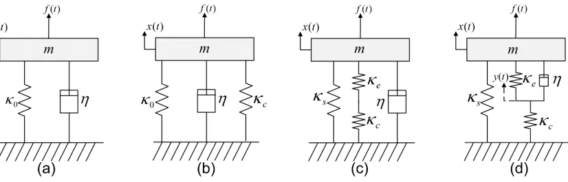
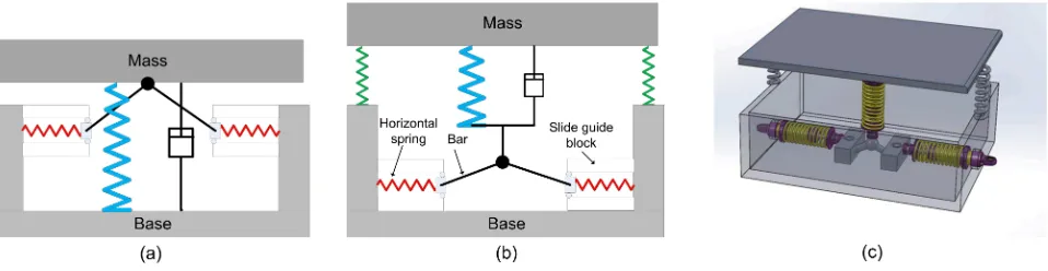
The design of the considered oscillator with the inclusion of a negative stiffness elementκcis introduced in Fig. 1, in dis-tinction to a classical linear SDoF oscillator, as well as to the known negative stiffness designs. Moreover, Fig. 2 presents a conceptual design of a vibration isolator designed according to the proposed oscillator, in distinction to the known negative stiffness oscillators.
The static stiffnessκst,m of the modified oscillator can be expressed as
κst,m=κs+
κeκc
κe+κc
(1)
[Figure 1 about here.]
κ0throughout this work, thusκ0 =κst,m. The two systems also comprise the same damping element of coefficientη.
[Figure 2 about here.]
The equations of motion for the DoF x,y of the modified system illustrated in Fig. 1 can be written as
m ¨x+η( ˙x−˙y)+κsx+κe(x−y)= f
η( ˙x−˙y)+κe(x−y)−κcy=0
(2a) (2b) or by combining Eqs. 2a, 2b
m ¨x+ksx+kcy= f (3) with f being the external excitation applied to the ’apparent’ DoF x. It is evident that an internal DoF hereby named y arises for the modified system in order to describe the displacement of theκcstiffness element. The system can therefore be character-ized as an oscillator with one apparent and one internal (hidden) DoF, taking into account Eq. 2b.
With the application of a Laplace transform the above sys-tem can be expressed as
s2mX+sη(X−Y)+κsX+κe(X−Y)=F sη(X−Y)+κe(X−Y)−κcY=0
(4a) (4b) Rearranging the terms in Eqs. 4a, 4b gives
s2mX+sηX+(κs+κe)X−(sη+κe)Y=F Y = sη+κe
sη+(κe+κc) X
(5a) (5b)
and by inserting Eq. 5b in 5a
[s2m+sη+(κs+κe)]X−
(sη+κe)2 [sη+(κe+κc)]
X =F (6)
In order to bring the transfer function of the system X/F to a convenient form from which the poles of the system can be computed Eq. 6 is written as
c1s3+c2s2+c3s+c4 [sη+(κe+κc)]
X=F (7)
with
c1=mη
c2=m(κe+κc)
c3=η(κs+κc) c4=κs(κe+κc)+κeκc
(8a) (8b) (8c) (8d) Therefore
X= [sη+(κe+κc)] c1s3+c2s2+c3s+c4
F (9)
with c1s3+c
2s2+c3s+c4being the characteristic equation of the modified system. The system will therefore have one real
and two complex poles in which case its transfer function can also be expressed as
X= [sη+(κe+κc)] mη(s+ρ)(s2+2ζ
nωns+ω2n)
F (10)
withρthe real pole of the characteristic equation,ζn the new damping ratio of the modified system andωnits new resonant frequency. At this point it should be noted that the mass my associated with the internal DoF y has been safely omitted as-suming that m ≫my. Accounting for a non-zero mass for the y DoF would induce a fourth order characteristic equation for Eq. 9 and therefore an additional condition to be satisfied for the stability of the oscillator. A second mass would also in-duce a second resonance for the two DoF system, which would however be frequency-wise much higher than the fundamental resonance. Comparing the denominators in Eqs. 9, 10 it can be observed that
ρ+2ζnωn=ξ=
κe+κc
η
2ρζnωn+ω2n=
κs+κc m ρω2n=ξω20
(11a)
(11b) (11c) In order for the system to be dynamically stable the following conditions should be satisfied
ρ≥0
ζn≥0
ωn≥0
(12a) (12b) (12c) Eqs. 11, 12 define the basic requirements and concepts for the design of the proposed oscillator. First, as a direct consequence of Eq. 12, it results that
ξ >0⇔κe+κc>0 (13) Furthermore, in order that the new oscillator exhibits maximum damping, the termζnωn should be maximum. Therefore, for a constantξ, and in view of Eq. 11a,ρshould be close to zero. In view of Eq. 11c, this in turn implies thatω0 andκ0 should be positive but close to zero. That is, the system should be designed close to the neutral stability point
κ0=κs+
κeκc
κe+κc
=0 (14)
2.2. Suggested engineering design
In order for the modified system to be equivalent to the SDoF oscillator the following relation is true for the static stiff -nesses of the two configurations
κ0=κs+
κeκc
κe+κc
(15)
κs=ακ0 (16) withα≥1. It is evident that forα=1 the system will converge to the SDoF oscillator behaviour and that for greater values of
αthe negative term κeκc
κe+κc will be responsible for reestablishing
Eq. 15. The second relation is derived by considering that an engineering safety margin ε should exist for the selection of
κc, prohibiting it to reach its limit value, that would result to a statically unstable structure:
κs+
(1+ε)κcκe (1+ε)κc+κe
=0 (17)
For the system to be statically stable it is assumed that ε >
0. Solving the system of Eqs. 15-17 the design values for the stiffnesses are obtained as
κe=κ0
εα(α−1) 1+ε−αε κc=−κ0
εα(α−1) 1+ε
(18a)
(18b)
From Eq. 18 and forα >1 it can be observed that
κe>0⇔1+ε > αε⇔α < 1+ε
ε κe+κc>0
(19a) (19b) are implied design limitations of the system. It is interesting to notice that Eqs. 18,19 fully satisfy the necessary and sufficient conditions for static stability, independently derived in [17].
3. Optimal parameter selection and analysis of the response of the proposed oscillator
It would be strongly beneficial for the designer to directly derive the design parameters for the stiffnessesκs,κe, κc as a function ofκ0, ω0, m,η and the desired values ofζn andωn. This can indeed be done by introducing Eqs. 17,18 in Eq. 11 and subsequently solve forζnandωnas a function of the design variablesα,εand the characteristics of the SDoF oscillatorκ0,
η, m. Due to the complexity of the resulting equations however this optimisation procedure is outside the scope of this work.
Eq. 10 implies that the new considered oscillator is dynami-cally equivalent to a SDoF oscillator with a new apparent damp-ing ratio ζn and natural frequencyωn, since the value ofρis always positive. Moreover, Eqs. 18, 19 imply that the absolute values of the stiffness elementsκs, κe,κcare greater than the stiffnessκ0of the original oscillator.
Consequently, a parametric analysis is performed to exam-ine the effect of the freely selectable parameters α andε on the resulting values of the stiffness elements, as well as on the apparent dynamic parametersωn andζn. The analysis is per-formed for a reference initial linear oscillator with non-dimensional value ofω0=2πrad/sec,ζ0=0.01 andκ0=1 N/m.
3.1. Selection of the stiffness design values
The approach involves the examination of the effect of the design parametersα,ηandεon the stiffness valuesκs,κeand
κcof the oscillator considered.
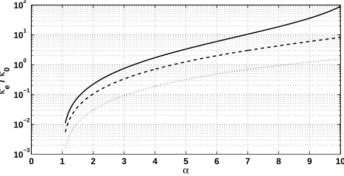
The results on the dependence of κeonαare presented in Fig. 3.
[Figure 3 about here.]
It is observed that increasingεwill demand a higher stiff -ness forκein order for a certain static stiffnessκ0to be retained. This difference is as significant as 500% when comparing the values betweenε=1.5%, ε=10%, for α=10. It is also shown thatκeincreases monotonically withκs.
[Figure 4 about here.]
In Fig. 4 similar results are exhibited, this time for stiffness
κc. Again it is observed that in order for a certain static stiffness
κ0 to be retained a more significant negative stiffness will be demanded forκc. It can therefore generally be concluded that considering the design of the oscillator it is more practical to choose a lowεvalues.
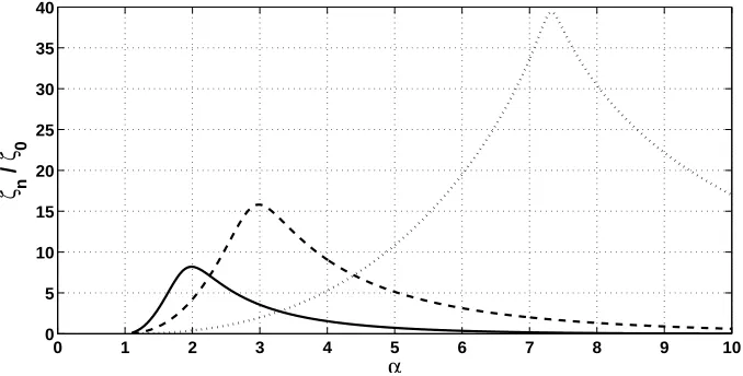
3.2. Parametric damping analysis of the proposed oscillator One of the most important design objectives for the oscil-lator is maximizing its damping characteristics. The damping ratioζnof the modified system can be calculated as a function of the poles of the characteristic equation of the system. In Fig. 5 the values ofζn as a function ofαand for variousε val-ues are presented. The results are given as the ratio ofζnto the damping ratio of the SDoF system
ζ0=
η
2√mκ0
(20)
It is shown that for everyεvalue an optimalαvalue exists for maximizingζn. The lower theεvalue, the greater the optimal value of the attainedζn. For higherαvalues,ζnconverges to the statically equivalent SDoF system. It can also be concluded that increasingεwill significantly decrease the optimalα.
[Figure 5 about here.]
A similar graph exhibiting the attained damping ratioζnfor various values of the damping coefficient η of the dashpot is shown in Fig. 6. Again an optimalαvalue seems to exist for anyηin order to maximize the damping ratio of the system. As expected, increasingηincreasesζn; however this increase is not linear. Taking a look at the maximumζn values it is observed that increasingηby a factor of 100 will only increase the max-imumζnby a factor of 4. Comparing the maximumζn values toζ0it is observed that forζ0 =1% the damping ratio is ampli-fied by a factor of 18, while forζ0=0.1% the damping ratio is increased by a factor of 100. It can therefore be concluded that an impressive improvement of the damping capabilities takes place for the modified system; this improvement is greater for lightly damped systems.
3.3. Impact of the design on the natural frequency of the oscil-lator
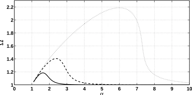
It is hereby stressed that the natural frequencyωn of the modified oscillator is also dependent onαand can be calculated as a function of the poles of the characteristic equation. In Fig. 7 the ratioΩ =ωn/ω0is exhibited as a function ofαfor various
ε values. It is observed that decreasingε increasesΩ. This increase becomes more significant when getting closer to the stability limit limε → 0+. For greaterαvaluesΩconverges to unity and the configuration is deprived of any exceptional damping behavior.
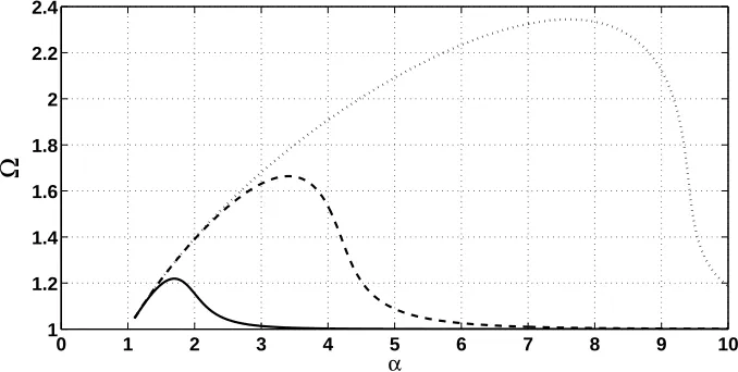
In Fig. 8,Ωis plotted as a function ofαfor various values ofζ0. It is shown that a greaterηwill increase the natural fre-quency of the modified system. Again, for higherαvaluesΩ
converges back to unity.
[Figure 7 about here.]
[Figure 8 about here.]
3.4. Frequency domain response
Using Eq. 7 the frequency response function FRF of the response X can be expressed as
X F =
iωη+(κe+κc) c1(iω)3+c2(iω)2+c3(iω)+c4
(21)
with the coefficients cigiven by Eq. 8.
Observing Figs. 5-8 it is evident that among others, two de-sign options exist for minimizing the response of the system; the first one being the choice of a value forα that will maxi-mize ζn. The second option would be selecting a value forα that would maximize the resonance frequency of the system, in which case the resonance band of the SDoF system would be transformed into a low frequency/low response regime.
In Figs. 5,7, it can be observed that minimizingεwill result in increasedΩandζn values for the system. It can therefore be assumed that an optimal performance will be attained for limε→0+. In Fig. 9 a low value forεof 1% is inserted in the
calculations. The results show a drastic reduction of the FRF X/F. For anΩoptimalαa maximum reduction of 2100% in the response of the system is observed. The reduction is slightly less impressive for aζn maximizingαparameter. In the high frequency range the responses seems to converge to that of the SDoF system.
[Figure 9 about here.]
3.5. Transient response and impact isolation capacities
The first part of the numerical case studies is dedicated to investigating the time domain response of the system. In order to solve for the time dependent response the system of equa-tions in Eq. 2 will be expressed in a state-space form with
x1=x
x2= ˙x x3=y
(22a) (22b) (22c)
Inserting Eq. 2b into 2a and rearranging the terms
m ¨x+κsx+κcy= f ⇔ ¨x=( f −κsx−κcy)/m
η˙y=η˙x+κe(x−y)−κcy⇔˙y= ˙x+
κe
η(x−y)− κc
ηy
(23a) (23b)
Therefore the derivatives can be written as
˙ x1=x2
˙
x2=( f −κsx1−κcx3)/m ˙
x3=x2+
κe
η(x1−x3)− κc
η x3
(24a) (24b) (24c)
The results can eventually be obtained by applying a Runge-Kutta numerical approach. A unitary initial velocity is consid-ered for y simulating thus a vibro-impact situation. The initial displacements are both set to zero. The valuesκ0, m andηfor the equivalent SDoF system are the same as aforementioned in Sec. 3.
In Fig. 10 the results for the time dependent response of ˙x, ˙y are exhibited. AnΩoptimalαvalue is hereby considered. It can be observed that the values attained by ˙y are much greater than the ones for ˙x as expected from the Y/X transfer function results presented in Fig. 12. The phase difference in the two curves is also evident.
[Figure 10 about here.]
In Fig. 11 the corresponding results for the time dependent forces applied within the modified system are exhibited. The phase difference between the stiffness forces and the inertial forces can be observed.
[Figure 11 about here.]
4. The physical background of the damping mechanism
4.1. The importance of the emergent phase∠Y/X
In view of Eq. 2, it is evident that if the amplitudes and the phases of X,Y were equal thenη( ˙x−˙y) =0 which means that the damping force and therefore the energy absorbed by the damping mechanism would inevitably be nil. The transfer function Y/X can be deduced by Eq. 5b while the FRF Y/F can be written as
Y F =
iωη+κe iωη+(κe+κc)
X= iωη+κe
c1(iω)3+c2(iω)2+c3(iω)+c 4
(25) In Fig. 12 the transfer function Y/X is shown for a range of αvalues. In Fig. 13 similar graphs for the phases of transfer functions∠X/F and∠Y/F are plotted. For highαvalues (much greater that the ones in the optimal range) the transfer function Y/X will converge to unity, suggesting that the response will converge towards the one of the original SDoF oscillator.
displacements. Furthermore∠X/F and∠Y/F diverge even in the low frequency range with a maximum divergence of approx-imately 1 radian which is in favour of maximizingζn.
[Figure 12 about here.]
[Figure 13 about here.]
It can generally be concluded that the impressive reduction of the X/F response of the modified system observed in Fig. 9 is underpinned by two factors, with the first one being the am-plification of the internal response Y of the system for low re-sponses of X. The second one exhibited in Fig. 13 being the emergence of a phase difference between the FRFs of X/F and Y/F, which increases the time averaged relative velocity ˙x-˙y.
The physical mechanism, responsible for the extraordinary vibration damping is better revealed by the analysis of the forces developed during the operation of the system. The forces can be calculated as
Fm=m ¨x⇒Fmt =(iω)mX Fs=ksx⇒Fst=ksX
Fc=kcy⇒Fct=kcY
Fe=ke(x−y)⇒Fet=keZ
Fh =η( ˙x−˙y)⇒Fht =(iω)ηZ
(26a) (26b) (26c) (26d) (26e) with Z=X−Y. In Fig. 14 the resulting real parts of the devel-oped forces are exhibited for the conventional SDoF oscillator. Since the applied external excitation is of unit amplitude, the sum of the real parts of the forces has to be equal to unity for all frequencies. In accordance to the classical theory of the linear SDoF oscillator, the real part of the elastic and inertial forces become zero in the vicinity of the resonance leaving solely the damping force to counteract the external excitation.
The results for the suggested configuration when an optimal
αdesign value is chosen are shown in Fig. 15. The external ex-citation curve (equal to unity throughout the frequency range) is omitted for the sake of conciseness. It is observed that in the vicinity of the new resonance of the systemωnthe positive stiffness and inertial forces become zero, however in this case it is the the real part of the force provided by the negative stiff -nessκcthat contributes to counterbalancing the external excita-tion. This phenomenon can be attributed to the phase difference
∠X/F described above.
[Figure 14 about here.]
[Figure 15 about here.]
A further interesting result of Figs. 14, 15 is the fact that the peak real part of the damping force of the considered oscilla-tor is significantly less than that of the reference SDoF system, despite the extraordinary damping behaviour.
4.2. Transient energy flow analysis in the proposed oscillator
A transient energy flow analysis is further considered in or-der to give further insight on how the damping of the oscillator
is increased compared to the SDoF system. About the energy flow it is known that
dEt
dt +η( ˙x−˙y)
2= f ˙x (27)
with Etthe total mechanical energy in the oscillator defined as
Et=Ep+Em
Em= 1 2m ˙x
2
(28a)
(28b)
with Emthe total kinetic energy and Epthe total potential en-ergy calculated as
Ep=Es+Ee+Ec
Es= 1 2κsx
2
Ee= 1
2κe(x−y) 2
Ec= 1 2κcy
2
(29a)
(29b)
(29c)
(29d)
Further elaboration of equation Eq. 29 leads to
˙
Es+E˙e+E˙c+E˙m+η( ˙x−˙y)2= f ˙x ˙ Es=κsx ˙x
˙
Ee=κe(x−y)( ˙x−˙y) ˙
Ec=κcy˙y ˙
Em=κs˙x ¨x
(30a) (30b) (30c) (30d) (30e)
while the corresponding equation for the original reference SDoF oscillator is
˙
Ep0+E˙m0+η˙x2= f ˙x
˙ Ep0=
d(κ0x2/2) dt =κ0x ˙x ˙
Em0=
d(m ˙x2/2) dt =m ˙x ¨x
(31a)
(31b)
[image:6.595.386.484.489.556.2](31c)
Fig. 16 depicts the rate of change of the potential energy, of the kinetic energy and of the power dissipated in the damper for the equivalent original linear oscillator. A phase difference of 180oexists between the rate of change of the total potential en-ergy and the kinetic enen-ergy. Thus, in view of Eq. 31, a minimal amount of power is absorbed in the damper.
[Figure 16 about here.]
the potential energies of the positive stiffness springs. This in-dicates that the role of the negative stiffness spring in the energy transfer is similar more to that of an inertial element, than to that of a conventional spring.
[image:7.595.311.587.601.678.2][Figure 17 about here.]
Fig. 18 depicts the rate of change of the total potential en-ergy, of the kinetic energy and of the power dissipated in the damper. Similarly to Fig. 16, a phase difference of almost 180o exists between the rate of change of the total potential energy and the one of the kinetic energy. In view of Eq. 30, this results to the activation of the damping forces and thus, a significant amount of power is absorbed in the damper.
[Figure 18 about here.]
5. Application to a periodic acoustic metamaterial lattice
In this numerical example section acoustic metamaterials are considered, in which one atom is replaced by the suggested oscillator configuration incorporating a negative stiffness ele-ment. Such metamaterials are shown to exhibit an extraordinary damping behavior, with a damping ratio to be even orders of magnitude higher than that of the original system. The concept proposed is general enough, able to lead to designs not only at a material level, but far more important, at the design of realistic engineering structures with periodic lattices, exhibiting extraor-dinary damping behavior, with absolutely no compromise at the structural stiffness.
The 1D wave propagation within an infinite sequence of pe-riodic lattices with negative stiffness inclusions is hereby exam-ined. The negative stiffness atom is used to replace the second linear oscillator (atom) used, in such a way that it retains the same static stiffness and the same damping element, however properly redesigned as per Sec. 2. The corresponding design is presented in Fig. 19.
[Figure 19 about here.]
The periodic segment, illustrated in Fig. 19 comprises a mass-in-mass configuration as in [9, 26] with the lumped mass mM
2 being included and connected to m M 1. Theκ
M
2 element used to connect the two masses in [9] is hereby replaced by the sug-gested oscillator containing a negative stiffness element atκM
c. The equations of motion for the modified system are as follows
m1M¨u1j+c1M( ˙u1j−˙u1j−1)−c1M( ˙u1j+1−˙u1j)+κ1M(u1j−u1j−1)−
−κ1M(u1j+1−u1j)−κMs (u2j−u1j)−κMc(vj−u1j)=0 m2M¨u2j+κsM(u2j−u1j)+κcM(vj−u1j)=0
ηM( ˙u2j−˙vj)+κeM(u j 2−v
j
)−κcM(v j
−u1j)=0
(32a) (32b) (32c)
with u1j, u2j being the displacements of masses 1, 2 belonging to the jth lattice. For the infinite periodic medium Bloch’s theo-rem [37] can be engaged in order to write a generalized relation for the displacements as
uhj+n=eik(nl)+λtUh uhj−n=eik(−nl)+λtUh
uhj=eλtUh vj=eλtV
(33a) (33b) (33c) (33d) with h=1, 2 standing for the index of the considered mass,±nl is the total distance from the reference lattice j to the considered lattice j±n; Uh,V are the wave motion amplitudes, k represents the wavenumber andλis a complex frequency function permit-ting time induced wave attenuation. In the absence of damping,
λ = ±iωso that the usual form of Bloch’s theorem is recov-ered. In the presence of damping the real part ofλrepresents the attenuation of the wave in which case
λw(k)=−ξw(k)ωu(k)±iωd(k) (34) withξwthe damping ratio of the considered wave type w andωd the frequency at which the assumed wavenumber value for the damped wave is occurring and where the values of ep, enandγ
are defined as follows
eikl=ep e−ikl=e
n
γ=2(1−ep+en)=2(1−cos kl)
(35a) (35b) (35c) The system in Eq. 32 can be reformulated by considering the following state space representation
z1=U1
z2=U˙1 z3=U2
z4=U˙2 z5=V
(36a) (36b) (36c) (36d) (36e) As a result, it can be cast into the following state space formu-lation λM z1 z2 z3 z4 z5 M =
0 1 0 0 0
−γκ M
1+κMs+κMc
mM
1 −
γcM
1 mM 1 κM s mM 1
0 κcM
mM
1
0 0 0 1 0
κM
s+κMc
mM
2
0 −κMs
mM
2
0 κcM
mM
2
κM
c
ηM 0
κM
e
ηM 1 −
κM
e+κMc
ηM z1 z2 z3 z4 z5 M (37) The complex values ofλMthat satisfy Eq. 37 can be sought by solving the resulting eigenvalue problem
type w having a wavenumber equal to kwand inducing structural displacements in the metamaterial lattice implied by zMw.
Numerical results considering the wavenumbers as well as the damping ratios for each wave type propagating within the configuration presented in Fig. 19 will hereby be presented. For the sake of comparison, results computed for the statically equivalent structures with no negative stiffness inclusions (as presented in [9]) will also be exhibited alongside. The consid-ered AM configuration has κM
1 = 4.182×10 4,κM
2 = κ M 1 /5 = 8.364×10³, mM
1=1 and m M 2 = 5m
M
1=5. The damping coeffi -cient is chosen asηM=1. A value forε=3% was selected for the design of the system and a parametric survey was conducted to decide the optimal corresponding value forα=2.5 which maxi-mizes its damping properties.
The dispersion curves of the waves propagating within the infinite waveguide are presented in Fig. 20. It can be observed that in the low frequency range the acoustic wave branches coincide for the two configurations with and without negative stiffness inclusions. The most interesting finding is the signif-icant increase of the band-gap between the propagating waves especially in the low wavenumber range where the ’dead zone’ has increased by 50% from 100 rad/sec to 150 rad/Sec. Both the acoustic and the optical wave branches seem to present a signif-icant reduction of k for the sameωd. This alteration is implied by a significant increase of the damping ratio as investigated below.
The structural damping ratios for each wave type as com-puted by the eigenvalues of Eq. 37 through Eq. 34 are exhibited in Fig. 21. A radical increase of the damping ratio can be ob-served for the acoustic wave branch in the region k ∈ [π/8, π] withξbeing increased by a factor of up to 105, compared to the original system having no negative stiffness inclusions. For the optical wave the damping ratio is 25 times higher for the mod-ified system for lim k → 0+, while for higher values of k the optical damping ratio presents a decrease, being only 2 times greater for the modified system. Regarding the total damping ratio of the two systems a dramatic increase is observed for the system comprising negative stiffness inclusions with itsξbeing increased by a factor varying between 21 and 34 for the entire wavenumber range.
[Figure 20 about here.]
6. Conclusion
The theoretical framework presented in his paper exhibits that statically and dynamically stable oscillators, incorporating negative stiffness elements can be designed. Summarising the main conclusions of the work:
(a) Once these oscillators are optimally designed according to the theory presented, they present an extraordinary damp-ing behavior, with an apparent dampdamp-ing ratio to be even several orders of magnitude higher than that of the original system, es-pecially in the cases where the original damping of the system is low.
(b) Such a design is possible, without any need for com-promises in the overall stiffness of the structure. Although the
elastic members of the proposed system need to be redesigned in order to present a higher stiffness than that of the original system, such an increase is kept within reasonable engineering limits.
(c) The damping element in the proposed oscillator is able to generate a phase difference between the elastic forces of the positive and the negative stiffness elements of the system. As a result, the forces either of the positive stiffness elements, or of the negative stiffness element, or both of them, are of an adequate level to balance the inertia and the excitation forces in the entire frequency range.
(d) A resonance phenomenon, although inherent and clas-sically observed in linear SDOF systems, cannot emerge in the proposed linear oscillator.
(e) Such an oscillator concept presents the potential for nu-merous implementations in a large variety of technological ap-plications, either as a discrete vibration isolator, or in the form of periodic metamaterials and composite structures. Moreover, further applications may emerge in a multiphysics environment, for instance in active vibration systems, or in electrical circuits with ’negative’ capacitance elements.
References
[1] E. Rivin, Passive vibration isolation, AS ME Press New York, 2003. [2] J. M. Kelly, D. Konstantinidis, Mechanics of rubber bearings for seismic
and vibration isolation, John Wiley & Sons, 2011.
[3] Y. Wang, M. Ludwigson, R. Lakes, Deformation of extreme viscoelastic metals and composites, Materials Science and Engineering: A 370 (2004) 41–9.
[4] R. Lakes, Extreme damping in composite materials with a negative stiff -ness phase, Physical Review Letters 86 (2001) 2897–8.
[5] M. Sigalas, E. Economou, Band structure of elastic waves in two dimen-sional systems, Solid state communications 86 (1993) 141–3.
[6] M. S. Kushwaha, P. Halevi, L. Dobrzynski, B. Djafari-Rouhani, Acoustic band structure of periodic elastic composites, Physical Review Letters 71 (1993) 2022–3.
[7] M. Hussein, M. Leamy, M. Ruzzene, Dynamics of phononic materials and structures: Historical origins, recent progress and future outlook, Ap-plied Mechanics Reviews, In review (2013).
[8] Z. Liu, X. Zhang, Y. Mao, Y. Zhu, Z. Yang, C. Chan, P. Sheng, Locally resonant sonic materials, Science 289 (2000) 1734–6.
[9] M. I. Hussein, M. J. Frazier, Metadamping: An emergent phenomenon in dissipative metamaterials, Journal of Sound and Vibration 332 (2013) 4767–74.
[10] K. Virk, A. Monti, T. Trehard, M. Marsh, K. Hazra, K. Boba, C. Remil-lat, F. Scarpa, I. Farrow, SILICOMB PEEK Kirigami cellular structures: mechanical response and energy dissipation through zero and negative stiffness, Smart Materials and Structures 22 (2013) 084014.
[11] E. Baravelli, M. Ruzzene, Internally resonating lattices for bandgap gen-eration and low-frequency vibration control, Journal of Sound and Vibra-tion 332 (2013) 6562–79.
[12] P. Michelis, V. Spitas, Numerical and experimental analysis of a triangular auxetic core made of CFR-PEEK using the Directionally Reinforced In-tegrated Single-yarn (DIRIS) architecture, Composites Science and Tech-nology 70 (2010) 1064–71.
[13] R. Lakes, P. Rosakis, A. Ruina, Microbuckling instability in elastomeric cellular solids, Journal of Materials Science 28 (1993) 4667–72. [14] V. Spitas, C. Spitas, P. Michelis, Modeling of the elastic damping
re-sponse of a carbon nanotube–polymer nanocomposite in the stress-strain domain using an elastic energy release approach based on stick-slip, Me-chanics of Advanced Materials and Structures 20 (2013) 791–800. [15] T. Jaglinski, D. Kochmann, D. Stone, R. Lakes, Composite materials with
[16] L. Dong, R. Lakes, Advanced damper with high stiffness and high hys-teresis damping based on negative structural stiffness, International Jour-nal of Solids and Structures 50 (2013) 2416–23.
[17] C. S. Wojnar, D. M. Kochmann, A negative-stiffness phase in elastic composites can produce stable extreme effective dynamic but not static stiffness, Philosophical Magazine 94 (2014) 532–55.
[18] W. Molyneaux, Supports for vibration isolation, ARC/CP-322, Aeronau-tical Research Council, Great Britain, 1957.
[19] D. L. Platus, Negative-stiffness-mechanism vibration isolation systems, In: SPIE’s International Symposium on Optical Science, Engineering, and Instrumentation (1999) 98–105.
[20] J. Winterflood, D. Blair, B. Slagmolen, High performance vibration iso-lation using springs in euler column buckling mode, Physics Letters A 300 (2002) 122–30.
[21] L. Virgin, R. Davis, Vibration isolation using buckled struts, Journal of Sound and Vibration 260 (2003) 965–73.
[22] R. Plaut, J. Sidbury, L. Virgin, Analysis of buckled and pre-bent fixed-end columns used as vibration isolators, Journal of Sound and Vibration 283 (2005) 1216–28.
[23] L. Virgin, S. Santillan, R. Plaut, Vibration isolation using extreme geo-metric nonlinearity, Journal of Sound and Vibration 315 (2008) 721–31. [24] R. DeSalvo, Passive, nonlinear, mechanical structures for seismic
attenu-ation, Journal of Computational and Nonlinear Dynamics 2 (2007) 290–8. [25] A. Carrella, M. Brennan, T. Waters, Static analysis of a passive vibration isolator with quasi-zero-stiffness characteristic, Journal of Sound and Vi-bration 301 (2007) 678–89.
[26] H. Huang, C. Sun, G. Huang, On the negative effective mass density in acoustic metamaterials, International Journal of Engineering Science 47 (2009) 610–7.
[27] C.-M. Lee, V. Goverdovskiy, A. Temnikov, Design of springs with neg-ative stiffness to improve vehicle driver vibration isolation, Journal of Sound and Vibration 302 (2007) 865–74.
[28] T. D. Le, K. K. Ahn, A vibration isolation system in low frequency exci-tation region using negative stiffness structure for vehicle seat, Journal of Sound and Vibration 330 (2011) 6311–35.
[29] C.-M. Lee, V. Goverdovskiy, A multi-stage high-speed railroad vibration isolation system with negative stiffness, Journal of Sound and Vibration 331 (2012) 914–21.
[30] H. Iemura, M. H. Pradono, Advances in the development of pseudo-negative-stiffness dampers for seismic response control, Structural Con-trol and Health Monitoring 16 (2009) 784–99.
[31] A. A. Sarlis, D. T. R. Pasala, M. Constantinou, A. Reinhorn, S. Nagara-jaiah, D. Taylor, Negative stiffness device for seismic protection of struc-tures, Journal of Structural Engineering 139 (2012) 1124–33.
[32] C.-M. Lee, V. Goverdovskiy, S. Samoilenko, Prediction of non-chaotic motion of the elastic system with small stiffness, Journal of Sound and Vibration 272 (2004) 643–55.
[33] A. Carrella, M. Brennan, T. Waters, V. Lopes Jr, Force and displacement transmissibility of a nonlinear isolator with high-static-low-dynamic-stiffness, International Journal of Mechanical Sciences 55 (2012) 22–9. [34] I. Kovacic, M. J. Brennan, T. P. Waters, A study of a nonlinear vibration
isolator with a quasi-zero stiffness characteristic, Journal of Sound and Vibration 315 (2008) 700–11.
[35] A. Shaw, S. Neild, D. Wagg, Dynamic analysis of high static low dy-namic stiffness vibration isolation mounts, Journal of Sound Vibration 332 (2013) 1437–55.
[36] X. Huang, X. Liu, J. Sun, Z. Zhang, H. Hua, Vibration isolation charac-teristics of a nonlinear isolator using euler buckled beam as negative stiff -ness corrector: A theoretical and experimental study, Journal of Sound and Vibration 333 (2014) 1132–48.
List of Figures
1 (a): A typical (reference) SDoF dynamic system consisting of a mass m, a stiffnessκ0and a dashpotη. The system exhibits a natural frequencyω0 and a damping ratio ζ0. (b): A ’zero stiffness’ oscillator. A negative stiffness element is connected in parallel to the existing stiffness element of the oscillator, in order to reduce the natural frequency. (c): A single DoF system incorporating a negative stiffness elementκc. It is equivalent to the reference SDoF system, when the values of the stiffness elements are selected according to Eq. 1. (d): The considered linear oscillator, resulting by the reallocation of the damping element and the introduction of an internal (hidden) DOF. . 12 2 Realisations of negative stiffness configurations. (a): A ’zero stiffness’ isolator. The ’zero stiffness’ spring is
realised by two horizontal springs in precompression, providing a negative stiffness in the vertical direction. (b): The considered isolator, resulting by an appropriate redistribution of the stiffness and damping elements. (c): A 3D realisation of the considered isolator. . . 13 3 The relation of the ratioκe/κ0to the design parameterα=κs/κ0in order for the considered system to retain a static
equivalent stiffnessκ0for various values of the safety margin design parameterε:ε=1.5% (· · ·),ε=5% (- -),ε=10% (–). All computations conducted withζ0=0.01. . . 14 4 The relation of the ratioκc/κ0toαin order for the considered system to retain a static equivalent stiffnessκ0:ε=1.5%
(· · ·),ε=5% (- -),ε=10% (–). All computations conducted withζ0=0.01. . . 15 5 The impact of theεparameter on the damping ratio enhancementζn/ζ0 of the considered system: ε=1.5% (· · ·),
ε=5% (- -),ε=10% (–). All computations conducted withζ0=0.01. . . 16 6 The impact of ηon the damping ratio enhancementζn/ζ0 of the considered system: ζ0=0.1 (· · ·),ζ0=0.01 (- -),
ζ0=0.001 (–). All computations conducted withε=3%. . . 17 7 The impact of theεparameter on the ratioΩ =ωn/ω0of the considered system:ε=1.5% (· · ·),ε=5% (- -),ε=10%
(–). All computations conducted withζ0=0.01. . . 18 8 The impact of the damping coefficientη =2ζ0√mκ0 on the ratio Ω = ωn/ω0 of the considered system: ζ0=0.1
(· · ·),ζ0=0.01 (- -),ζ0=0.001 (–). All computations conducted withε=3%. . . 19 9 An attempt to minimise the displacement FRF X( f ) of the considered system atω0: i) By choosing anΩoptimal
α=8.6 (–). ii) By choosing aζn optimalα=10.2 (- -). i) By choosing an intermediate valueα=9.4 (· · ·). Also exhibited the original SDoF system response (-·-). All computations conducted withζ0=0.01,ε=1%. . . 20 10 Time dependent velocities ˙x and ˙y of the modified system under a unit impulse: ˙y (–), ˙x (- -). All computations
conducted withε=5%,ζ0=0.01,α=2.4 (Ωoptimal) . . . 21 11 Time dependent forces of the modified system under a unit impulse: Fks(–), Fm(- -), Fkc(· · ·). All computations
conducted withε=5%,ζ0=0.01,α=2.4 (Ωoptimal) . . . 22 12 The magnitude of the transfer function Y( f )/X( f ) for the considered system:α=2 (–),α=2.4 (Ωoptimal) (- -),α=3
(ζnoptimal) (· · ·),α=9 (-·-). All computations conducted withζ0=0.01,ε=5%. . . 23 13 The phase of X( f ) (- -) and Y( f ) (· · ·) forα=2.4 (Ωoptimal) and phase (–) of X( f ) for the original SDoF system.
All computations conducted withζ0=0.01,ε=5%. . . 24 14 Real part of forces applied in the conventional SDoF system: External force f (–), Elastic force (-·-), Inertial force
(- -), Damping force (· · ·). All computations conducted withα=2.4 (Ωoptimal),ζ0=0.01,ε=5%. . . 25 15 Real part of forces applied in the modified oscillator: Positive stiffness force Fst (-·-), Inertial force Fmt (- -),
Damping force Fht (· · ·), Negative stiffness force Fct (–). All computations conducted withα=2.4 (Ωoptimal),
ζ0=0.01,ε=5% . . . 26 16 Rate of change of the energies within the original SDoF oscillator: Rate of change of the potential energy (- -), Rate
of change of the kinetic energy (· · ·), Power dissipated in the damper (–). . . 27 17 Rate of change of the potential energies within the suggested oscillator: Rate of change of the potential energy of
κs(· · ·), Rate of change of the potential energy ofκc(-·-), Rate of change of the potential energy ofκe(- -), Rate of change of the total potential energy (–). . . 28 18 Rate of change of the energies within the suggested oscillator: Rate of change of the total potential energy (- -),
Rate of change of the kinetic energy (· · ·), Power dissipated in the damper (–). . . 29 19 Left: Illustration of an Acoustic Metamaterial (M) configuration as presented in [9]. Dashed line encloses the
considered periodic segment. Right: The modified Acoustic Metamaterial lattice with the second (internal) atom being replaced by a the proposed oscillator, incorporating a negative stiffness element atκcM. . . 30 20 Wavenumber k as a function ofωd for the acoustic wave within the acoustic metamaterial structure: Present
Figure 1: (a): A typical (reference) SDoF dynamic system consisting of a mass m, a stiffnessκ0and a dashpotη. The system exhibits a natural frequencyω0and a damping ratioζ0. (b): A ’zero stiffness’ oscillator. A negative stiffness element is connected in parallel to the existing stiffness element of the oscillator, in order to reduce the natural frequency. (c): A single DoF system incorporating a negative stiffness elementκc. It is equivalent to the reference SDoF system, when the
[image:12.595.95.508.326.459.2]0 1 2 3 4 5 6 7 8 9 10 10−3
10−2 10−1 100 101 102
α
κ e
/
[image:14.595.131.467.322.494.2]κ 0
0 1 2 3 4 5 6 7 8 9 10 −10
−8 −6 −4 −2 0
α
κ c
/
[image:15.595.133.467.326.486.2]κ 0
0 1 2 3 4 5 6 7 8 9 10 0
5 10 15 20 25 30 35 40
α
ζ n
/
[image:16.595.129.468.321.493.2]ζ 0
0 1 2 3 4 5 6 7 8 9 10 0
20 40 60 80 100
α
ζ n
/
[image:17.595.129.467.322.492.2]ζ 0
0 1 2 3 4 5 6 7 8 9 10 1
1.2 1.4 1.6 1.8 2 2.2
α
[image:18.595.132.468.322.489.2]Ω
Figure 7: The impact of theεparameter on the ratioΩ =ωn/ω0of the considered system:ε=1.5% (· · ·),ε=5% (- -),ε=10% (–). All computations conducted with
0 1 2 3 4 5 6 7 8 9 10 1
1.2 1.4 1.6 1.8 2 2.2 2.4
α
[image:19.595.129.468.321.492.2]Ω
0 0.2 0.4 0.6 0.8 1 1.2 1.4 1.6 1.8 2 10−1
100 101 102
Frequency [Hz]
[image:20.595.129.467.324.483.2]Transfer function [m/N]
Figure 9: An attempt to minimise the displacement FRF X( f ) of the considered system atω0: i) By choosing anΩoptimalα=8.6 (–). ii) By choosing aζnoptimal
α=10.2 (- -). i) By choosing an intermediate valueα=9.4 (· · ·). Also exhibited the original SDoF system response (-·-). All computations conducted withζ0=0.01,
0 0.5 1 1.5 2 2.5 3 3.5 4 −4
−2 0 2 4
Time [s]
[image:21.595.128.466.322.490.2]Velocity [m/s]
0 0.5 1 1.5 2 2.5 3 3.5 4 −0.2
−0.1 0 0.1 0.2 0.3
Time [s]
[image:22.595.129.467.324.488.2]Forces [N]
0 0.2 0.4 0.6 0.8 1 1.2 1.4 1.6 1.8 2 2
4 6 8 10 12
Frequency [Hz]
[image:23.595.131.467.324.489.2]|Y/X|
0 0.2 0.4 0.6 0.8 1 1.2 1.4 1.6 1.8 2 −4
−3 −2 −1 0
Frequency [Hz]
[image:24.595.128.466.324.488.2]Displacement phase [rad]
0 0.2 0.4 0.6 0.8 1 1.2 1.4 1.6 1.8 2 −30
−20 −10 0 10 20 30
Frequency [Hz]
[image:25.595.128.467.326.488.2]Real part of force [N]
0 0.2 0.4 0.6 0.8 1 1.2 1.4 1.6 1.8 2 −3
−2 −1 0 1 2 3
Frequency [Hz]
[image:26.595.127.466.324.489.2]Real part of force [N]
Figure 15: Real part of forces applied in the modified oscillator: Positive stiffness force Fst(-·-), Inertial force Fmt(- -), Damping force Fht(· · ·), Negative stiffness
0 0.1 0.2 0.3 0.4 0.5 0.6 0.7 0.8 0.9 1 −0.08
−0.06 −0.04 −0.02 0 0.02 0.04 0.06
Time [s]
[image:27.595.129.468.325.485.2]Energy rate of change [Watts]
0 0.1 0.2 0.3 0.4 0.5 0.6 0.7 0.8 0.9 1 −0.4
−0.2 0 0.2 0.4
Time [s]
[image:28.595.127.467.324.488.2]Energy rate of change [Watts]
0 0.1 0.2 0.3 0.4 0.5 0.6 0.7 0.8 0.9 1 −0.1
−0.05 0 0.05
Time [s]
Energy rate of change [Watts]
Figure 18: Rate of change of the energies within the suggested oscillator: Rate of change of the total potential energy (- -), Rate of change of the kinetic energy
Figure 19: Left: Illustration of an Acoustic Metamaterial (M) configuration as presented in [9]. Dashed line encloses the considered periodic segment. Right: The modified Acoustic Metamaterial lattice with the second (internal) atom being replaced by a the proposed oscillator, incorporating a negative stiffness element atκM
0 0.5 1 1.5 2 2.5 3 3.5 0
50 100 150 200 250 300 350 400 450
k [rad/m] ω d
[image:31.595.49.377.225.380.2][rad/s]
Figure 20: Wavenumber k as a function ofωdfor the acoustic wave within the acoustic metamaterial structure: Present approach with negative stiffness elements
(· · ·), No negative stiffness inclusions (-·-). Wavenumber k as a function ofωdfor the optical propagating wave: Present approach (–), Without negative stiffness
(- -). All computations conducted withα=2.5,ηM=1,ε=3%.
0 0.5 1 1.5 2 2.5 3 3.5
10−4
10−3
10−2
10−1
100
k [rad/m]
ξ
[image:31.595.41.399.402.579.2]