A model driven approach to model transformations.
APPUKUTTAN, Biju K, CLARK, Anthony
<http://orcid.org/0000-0003-3167-0739>, REDDY, Sreedhar, TRATT, Laurence and VENKATESH, R
Available from Sheffield Hallam University Research Archive (SHURA) at:
http://shura.shu.ac.uk/11893/
This document is the author deposited version. You are advised to consult the
publisher's version if you wish to cite from it.
Published version
APPUKUTTAN, Biju K, CLARK, Anthony, REDDY, Sreedhar, TRATT, Laurence and
VENKATESH, R (2003). A model driven approach to model transformations. In:
Workshop in Software Model Engineering (WiSME) 2003, San Francisco, October
2003. Springer Berlin Heidelberg.
Copyright and re-use policy
A model driven approach to building
implementable model transformations
Biju Appukuttan
1[email protected]
Tony Clark
2[email protected]
Sreedhar Reddy
3[email protected]
Laurence Tratt
2[email protected]
R. Venkatesh
3[email protected]
1
Tata Consultancy Services, Pune, India. On deputation to Kings College
London.
2
Department of Computer Science, King’s College London, Strand, London,
WC2R 2LS, United Kingdom.
3
Tata Consultancy Services, Pune, India.
Abstract
The OMG’s Model Driven Architecture (MDA) initiative has been the focus of
much attention in both academia and industry, due to its promise of more rapid
and consistent software development through the increased use of models. In order
for MDA to reach its full potential, the ability to manipulate and transform
mod-els – most obviously from the Platform Independent Model (PIM) to the Platform
Specific Models (PSM) – is vital. Recognizing this need, the OMG issued a Request
For Proposals (RFP) largely concerned with finding a suitable mechanism for
trans-forming models. This paper outlines the relevant background material, summarizes
the approach taken by the QVT-Partners (to whom the authors belong), presents
a non-trivial example using the QVT-Partners approach, and finally sketches out
what the future holds for model transformations.
1 Introduction - Transformations and MDA
The OMG Queries/Views/Transformations (QVT) RFP [1] defines the MDA vision thus: MDA defines an approach to IT system specification that separates the specification of system functionality from the specification of the implementation of that functionality on a specific technology platform, and provides a set of guidelines for structuring specifica-tions expressed as models.
standards... and allows different applications to be integrated by explicitly relating their models.
In less technical terms, MDA aims to allow developers to create systems entirely with models1. Furthermore, MDA envisages systems being comprised of many small, manageable models rather than one gigantic monolithic model. Finally, MDA allows systems to be designed independently of the eventual technologies they will be deployed on; a PIM can then be transformed into a PSM in order to run on a specific platform.
✂✁
[image:3.595.175.405.182.358.2]☎✄ ☎✆
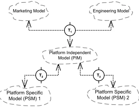
Fig. 1. Transformations and MDA
Figure 1 – based partly on a D’Souza example [2] – shows an overview of a typical usage of MDA. It shows a company horizontally split into multiple departments, each of which has a model of its system. These models can be considered to be views on an overall system PIM. The PIM can be converted into a PSM. In order to realize this vision, there has to be some way to specify the changes that models such as that in figure 1 undergo. The enabling technology is transformations. In figure 1 a transformation T1 integrates the company’s
horizontal definitions into an overall PIM, and a transformation T2 converts the overall
PIM into PSMs, one for each deployment platform.
The following are some representative MDA related uses where transformations are, or could be, involved:
• Integrating the components of a horizontal direction in a federated model. This is the
example used in figure 1
• Converting a model ‘left to right’ and/or ‘right to left’. This is a very common operation
in tools, for example saving a UML model to XML and reading it back in again.
• Abstracting a model. Abstracting away unimportant details, and presenting to the user
only the salient points of the model, is a vital part of MDA.
• Reverse engineering. For example, a tool which recovers Java source code from class files. • Technology migration. This is similar to reverse engineering, but whereas reverse
engineer-ing is simply tryengineer-ing to recover lost information, technology migration is effectively tryengineer-ing to convert outdated systems into current systems. For example, a tool which migrates legacy COBOL code to Java.
Transformations are undoubtedly the key technology in the realization of the MDA vision. They are present explicitly – as in the transformation of a PIM to a PSM – and implicitly – the integration of different system views – throughout MDA.
2 QVT
In order for MDA to reach its full potential, the ability to manipulate and transform mod-els is vital. Although there has been much discussion [3,4] of the problem area, as well as attempts at filling this gap in the past [5–8], little practical progress has been made. Recog-nizing the need for a practical solution for transformations, the OMG issued a Request For Proposals (RFP) [1] largely concerned with finding a suitable mechanism for transforming models. This paper is based on the QVT-Partners2 revised submission [9] to the QVT RFP.
3 Fundamental concepts
It is our view that to provide a complete solution to the problem of a practical definition of transformations, the following complimentary parts are necessary:
(1) The ability to express both specifications and implementations of transformations. (2) A mechanism for composing transformations.
(3) Standard pattern matching languages which can be used with declarative and imper-ative transformations.
(4) A complete semantics, which are defined in terms of existing OMG standards. The solution outlined in this paper can be seen to be chiefly concerned with solving two overarching problems: the need to provide a framework into which different uses of trans-formations can be accommodated, and the need to provide a standard set of languages for expressing transformations. In solving these needs, the solutions to other fundamental requirements as mentioned earlier in this section follow fairly automatically.
4 A definition of transformations
This section outlines the points of our definition of transformations that are most relevant to this paper.
4.1 Framework
We define an overall framework for transformations that allows one to use a variety of dif-ferent transformation styles. This framework also transparently allows transformations to change style throughout the lifetime of a system. Such transparency is enabled by identifi-cation of two distinct sub-types of transformations: relations and mappings.
Mappings are transformation implementations. Unlike relations, mappings are potentially uni-directional and can return values. Mappings can refine any number relations, in which case the mapping must be consistent with the relations it refines.
✝
✞ ✟ ✠
✡ ☛ ☞
✌
✍
✎
[image:5.595.150.431.124.223.2]✏✑✏✑✒✓✔✕✖✗✓✘✑✙✗✙
[image:5.595.225.355.317.383.2]Fig. 2. A high level relation being refined by a directed mapping
Figure 2 shows a relationRrelating two domains. There is also a mappingMwhich refines relation R; since M is directed, it transforms model elements from the right hand domain into the left hand domain.
Transformation
Mapping Relation
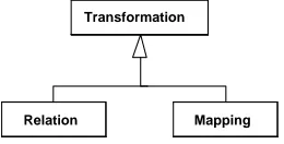
Fig. 3. Transformations, relations and mappings in the MOF hierarchy
Figure 3 shows how transformations, relations and mappings are placed within the MOF [10] hierarchy. AsTransformationis a super-type of RelationandMapping, when we talk about a transformation we effectively mean either a relation or a mapping, we don’t mind which one. When we talk about a mapping, we specifically mean a mapping and only a mapping and similarly for relations.
The identification and separation of transformation specifications and implementations, as relations and mappings respectively, gives several benefits to the modeller. These include giving the modeller the ability to:
• use relations in the initial stages of system development when implementation details may
not have been fully decided upon. This allows transformations to be concretely discussed without an over-commitment to implementation details.
• write multiple mappings, possibly in completely different programming languages, which
refine a single relation.
• construct a relation from a pre-existing mapping to tease out details which would
other-wise be lost in the melange.
4.2 Pattern Languages
In order to facilitate transformations we define powerful a pattern matching language which is utilized by MTL. Pattern matching is a proven concept within transformation systems such as XSLT [W3C99] and textual regular expressions ‘a la Perl. The essential idea behind pattern matching is to allow the succinct expression of complex constraints on an input data type; data which matches the pattern is then picked out and returned to the invoker. MTL allows model fragments to be matched against meta-model patterns and used in transformations. Pattern languages are inherently a compromise between expressivity on the one hand, and brevity and legibility on the other. As is the case with most pattern languages, the pattern language we propose is not always the best way of expressing aspects of a particular transformation. To that end, domains in our standard relations and mappings languages are comprised of patterns and conditions. By utilizing conditions, arbitrarily complicated expressions can be specified to augment patterns. Furthermore, a separate condition is scoped over all domains which allows domains to be related to one another in a natural way. The general form of a relation when written in textual form is thus:
relation R { domain { pattern-1 when condition-1 } ...
domain {pattern-n when condition-n } when { condition }
}
The final condition is effectively a global condition which scopes over all domains. A relation is called with a number of arguments corresponding to its number of domains; each argument is either a single element, or it is a choice. A choice is a data set which contains zero or more objects, each of which may be tested to see if some combination of candidates satisifies the transformation choices come in both unordered and prioritised forms. The relation is only satisfied when all domains are satisfied. This is more complex than it may initially seem as there can be constraints which hold across more than one domain. Thus an arbitrary object o may satisfy one domain but cause another to fail; the semantics of MTL ensure that all domains must be satisfied, which means that a runtime engine may have to try different combinations to ensure the relation is satisfied.
A specific example involving patterns and conditions is the following:
relation IncreasingWisdom {
domain { (Person)[name = n, age = a, wisdom = w1] when a + 1 < 13 or a + 1 > 19 } domain {(Person)[name = n, age = a + 1, wisdom = w2] } when { w2 > w1 }
}
Intuitively, this example checks that a birthday brings with it increased wisdom, except during the teenaged years when this is not always the case. (Person)[name = n, age = a, wisdom = w1] whena >18 is an example of an object pattern, which take the general form
of:
(Class, self)[label1 = expr1, ... , labeln = exprn]
all match successfully against the object patterns fields note that the object pattern can specify a subset of the field which Class defines, although it cannot define more. The pattern language contains many other constructs, such as set and sequence patterns, and patterns can nest within patterns giving huge flexibility [9].
4.3 Differences between relations and mappings
Whereas a relation is a specification of a transformation which can check two models for conformance with each other with respect to the relation, a mapping is an implementation that can be run on an input data model to produce an output data model. Mappings take the general form of:
mapping M {
domain { pattern-1 when condition-1 } ...
domain {pattern-n when condition-n } when { condition }
body { expression } }
Although a mapping may have a number of domains, as do relations, there is a fundamental difference to the way multiple domains are used with mappings and relations. With map-pings, all the domains are effectively input arguments to the mapping which, providing the input data satisfies the domains, executes the body of the mapping to produce output. A mapping can refine one or more relation, which essentially means that the mapping must be consistent with the relations: in other words, the relations the mapping refines are effec-tively pre and post conditions for the mapping. There is no implication that a mapping is the only refinement of a relation multiple different mappings may refine the same relation. Mappings which refine trivial relations often look very similar because of the intentionally close syntactic correspondence between object expressions and patterns.
As far as possible, the standard languages for relations and mappings share the same syntax and semantics. But by virtue of the fact that they are different concepts there are differences between the two. The most obvious difference is that whilst a relation simply consists of a number of domains and an overall constraint, mappings also have an action body. A practical example is a mapping IncreasingWisdomMapping which is a refinement of the relation IncreasingWisdom given in subsection 4.2:
mapping IncreasingWisdomMapping refines IncreasingWisdom { domain { (Person)[name = n, age = a, wisdom = w1]
when a + 1 < 13 and a + 1 > 19 } body {
p = new Person() p.name = n p.age = a + 1 p.wisdom = w1 + 5 }
}
5 Transformations
Our definition of transformations comes in two distinct layers. Reusing terminology familiar from the UML2 process, we name these layersinfrastructure andsuperstructure.
Theinfrastructurecontains what we consider to be a sensible minimum of machinery neces-sary to support all types of transformations. The infrastructure is necessarily low-level and not of particular importance to end users of transformations. Its use is a simple semantic core [11].
Compared to the infrastructure, the superstructure [9] contains a much higher-level set of transformation types and is suitable for end users.
5.1 Concrete syntax
Our solution defines a graphical concrete syntax for transformations. Figure 4 lists the most important notations.
✚✜✛ ✚✣✢
✤
✥
Fig. 4. Concrete Syntax for transformations
6 Transformation Reuse
Our proposal allows two means by which transformations can be reused. They are as follows:
6.1 Transformation Composition
The submission provides various composition operators which allow complex transforma-tions to be built up from smaller transformatransforma-tions. They come in both unary and binary flavours and include operators such as and, not and or. To give a very simple example, anand composition would require all the individual components to hold for the composite relation to hold.
6.2 Sub-Transformation
This form of reuse involves one transformation calling another (sub) transformation. This usage typically occurs inwhen condition.
7 An example
7.1 The example model
UML Meta Model
Classifier Primitive DataType Class Association Attribute Operation src dest attrs * * operation type assoc
RDBMS Meta Model
Table Column Query Key ForeignKey query foreignkey key refersTo col col * * * * * fKeyOf
Fig. 5. The example meta-model
Figure 5 (left hand side) shows a very simplified model of UML Class diagrams which we will use to illustrate our approach. It consists of a Class having a set of Attributes and
operations. The attributes can be of typePrimitiveDataType or, of type Class. Classes also have Associations with other classes. Note: For the purposes of our current example we have assumed the attributes to be of type PrimitiveDataType only.
Figure 5 (right hand side) shows a simplified RDBMS model. It consists of aTable having a set of Columns, a primary Key, ForeignKeys andQueries. The Key comprises columns which are of the kindprimary. Queries are performed on Tables to either extract information from it or, to update some information.
In the rest of this section, we shall gradually build up the transformation between the UML model and the RDBMS model from a number of small pieces.
cXt name=cn
kind=’Persistent’ Class
name= ”t_” + cn Table
name= ”k_” + cn Key key
Fig. 6. A UML Class to Table relation
Figure 6 shows the relationcXt between Classes and Tables. Herein, each class ofkind =
persistent gets transformed to a corresponding Table and a Key (primary) element having the same name as the class, but prefixed with a ”t ” and ”k ” respectively (The naming may be altered to suit the local database naming conventions). This relation may be represented textually as follows:
relation cXt{
domain {(Class)[ name = cn, kind = "persistent" ]} domain {(Table)[ name = "t_" + cn ,
key = (Key)[ name = "k_" + cn ]] }
}
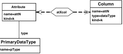
Figure 7 captures the relation atXcol between Attributes of the class and the columns of the table. Basically, each attribute of the class gets transformed to a corresponding column of the table. The dataType of the column is typically set to either Number or Varchar depending on the type of the attribute. The textual representation is as follows:
relation atXcol{
type
atXcol name=attN
kind=k Attribute
name=attN type=dataType kind=k
Column
[image:10.595.192.391.73.161.2]name=pType PrimaryDataType
Fig. 7. Attributes to Columns relation
type = (PrimitiveDataType)[ name = pType] ] }
domain { (Column)[ name = attN, kind = k, type = dataType ] } when { dataType = if (pType = ’Integer’) ’number’ else ’varchar’ } }
The above relation is valid in the case of Attributes of type PrimitiveDataType only. In the case of attributes of type Class, the type Class is broken down further into its attributes, and each individual attribute of the Type Class is added to the generated table as a column with an altered name as per the naming convention. The columns which are generated are of a type (i.e. datatype) corresponding to the type PrimaryDataType only.
A:Attribute attrs *
clAtXtbCo name=cn
kind=”Persistent” Class
name= ”t_” + cn Table
name= ”k_” + cn Key
C:Column col
col
*
key
*
kind=”primary” PC:Column
[image:10.595.111.457.530.665.2]Fig. 8. Classes and Attributes relation
Figure 8 shows the combined view of the transformation of Classes and Attributes. Note that attributes of the primary kind, apart from being transformed into Columns, result in an association with the Key object of the table as well. This is textually (clAtXtbCo) represented as follows:
relation clAtXtbCo{
domain { (Class)[ name = cn, kind = "persistent", attrs = A] } domain { (Table)[ name = "t_" + cn,
col = C,
key = (Key) [ name = "k_" + cn, col = PC] ] }
when {
conjunct( A->forAll(a | AtXcol(a, C.tochoice())), C->forAll(c | AtXcol(A.tochoice(), c)), PC = C->select(c| c.kind = ’primary’) ) }
}
ascXfky
kind=’Persistent’ end1:Class
kind=’Persistent’ end2:Class
end1:Table
end2:Table foreignKey
k:Key refersTo
key
C:Column
col col
src dest
fkeyOf name=ascN
Association
name=”f_” + ascN ForeignKey
kind=’Primary’ A:Attribute
attrs
(a)
Attribute
PrimitiveData Type
kind=’Foreign’ Column apXc
type
(b)
[image:11.595.149.429.67.340.2]kind=”Foreign” CF:Column col
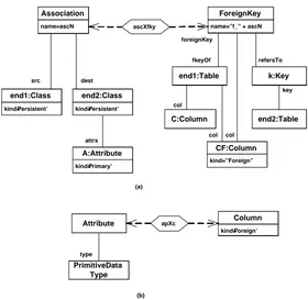
Fig. 9. Transformation of Associations
Transformation of Associations, as shown in figure 9(a) is a little less straightforward com-pared to the other transformations which have been covered so far. In this case, the For-eignKey element is introduced to relate the two tables corresponding to the two classes that the association relates. We assume src to represent the source of the association and dest
to represent the destination of the association. The transformation results in a Foreign key being defined for the Table corresponding to the source class. This foreignKey refers to the key of the table corresponding to the destination Class of the association. All the primary key columns of the destination class are added to the source table with the column kind being set toforeign (figure 9(b)). This relation is textually represented as follows:
relation ascXfkey{
domain { (Association)[ name = ascN, end1 = src,
end2 = (Class, dest)[ attrs=A ] ] }
domain { (ForeignKey)[ name = "f_" + ascN,
fKeyOf = (Table, srcTbl) [ col = C ], refersTo = (Key, k)[ keyOf = destTbl ], col = CF ]
} when {
conjunct( cXt(src, srcTbl), cXt(dest, destTbl),
((A->select(a | a.kind=’Primary’))->forAll(at| atXcol(at, CF.tochoice()))),
(CF->forAll(cf | atXcol((A->select(a |
a.kind=’Primary’).tochoice(), cf)))) ) }
Figures 6 through to figure 9 show the building blocks based on which a UML model is transformed into a corresponding RDBMS model. Thus, the final RDMBS model will be a composition of the above mentioned basic transformations. The textual representation of the complete relationclsAttrAscXtblColFkey is as follows:
relation clsAttrAscXtblColFkey{
domain { (Class)[ name = cn, kind = "persistent", attrs = A , assoc = ASC]
}
domain { (Table)[ name = "t_" + cn, col = C,
foreignKey = F,
key = (Key) [ name = "k_" + cn, col = PC ] ] }
when {
conjunct( A->forAll(a | AtXcol(a, C.tochoice())), PC = C->select(c | c.kind = ’primary’), C->forAll(c | AtXcol(A.tochoice(), c)), ASC->forAll(asc | asXf(asc, F.tochoice())), F->forAll(f | AtXcol(ASC.tochoice(), f)) ) }
}
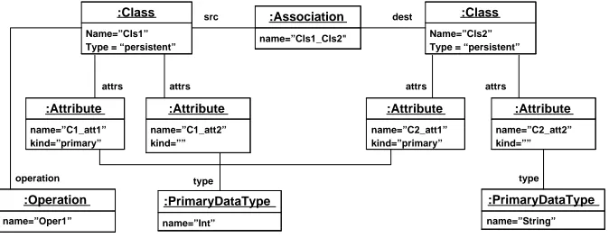
7.2 An example instance model
src dest
attrs
operation type
Name=”Cls1” Type = “persistent”
:Class
Name=”Cls2” Type = “persistent”
:Class
name=”C1_att1” kind=”primary”
:Attribute
name=”C1_att2” kind=””
:Attribute
name=”C2_att1” kind=”primary”
:Attribute
name=”C2_att2” kind=””
:Attribute
name=”Oper1” :Operation
name=”Int” :PrimaryDataType
name=”String” :PrimaryDataType name=”Cls1_Cls2"
:Association
attrs attrs attrs
[image:12.595.122.459.396.528.2]type
Fig. 10. An Example UML Model
We now illustrate the transformation by means of an actual example. Figure 10 represents an example UML model. It consists of two classesCls1 andCls2 having two attributes each as shown in the figure. As mentioned earlier, for the purposes of our illustration we will be specifying Attributes to be of the type PrimaryDataType only. The AttributeC1 att1
of Class Cls1 as well as Attribute C2 att1 of Class Cls2 have their kind set to primary. Cls1 has an operation Oper1 attached to it. Cls1 and Cls2 are also linked together by an
Association as shown in the figure.
col
query
name=”t_Cls1” :Table
name=”t_Cls2” :Table
name=”C1_att2” dataType=”Number”
:Column
name=”C1_att1” dataType=”Number”
:Column
name=”C2_att1” dataType=”Number”
:Column
name=”C2_att2” dataType=”varchar”
:Column
name=”q_Oper1” :Query
col col col
name=”k_Cls1” :Key
name=”k_Cls2” :Key
key
col col
foreignKey
refersTo
key name=”f_Cls1_Cls2"
:ForeignKey fKeyOf
name=”C2_att1” dataType=”Number” kind=”Foreign”
:Column
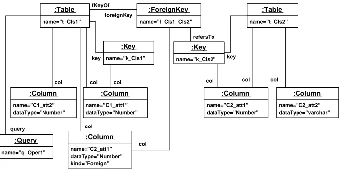
[image:13.595.118.463.72.243.2]col col
Fig. 11. The resultant RDBMS Model
7.3 Creating a Mapping
The example so far dealt with the relation between the UML Model and the RDBMS Model. In other words, given a UML model and a RDBMS model, we can check them using the relations specifications to see if they are valid transformations of each other.
However if we wanted to generate RDBMS model, given the UML model, then we would have to refine the specifications and create an implementation which can take in the UML model and generate an RDBMS model out of it. If one wished to actually transform a UML model to RDBMS and back again, then the relation would have to be refined to two separate mappings to implement it. As mentioned earlier in subsection 4.3, in the case of mappings, the second (target) domain gets substituted by an action body which implements the transformation based on the input domain.
We provide a mapping for a small subsection of the transformations example in subsection 7.1 consisting of Classes and Attributes only.
Consider the relation between Classes and Tables -cXt shown in subsection 7.1. A corre-sponding mapping is as follows:
mapping M_cXt refines cXt{
domain {(Class)[ name = cn, kind = "persistent" ]} body {(Table)[ name = "t_" + cn ,
key = (Key)[ name = "k_" + cn ]] }
}
Herein, the second domain (corresponding to table) is replaced by a body which contains an expression which creates the Table and the Key elements as per the specifications. This particular mapping is very simple.
Below we show a mapping of the relationatXcol which involves if conditions in thewhen
block:
mapping M_atXcol refines atXcol{
type = (PrimitiveDataType)[ name = pType ] ] }
body { (Column)[ name = attN, kind = k,
type = if (pType = ’Integer’) ’number’ else ’varchar’] } }
In this mapping, thewhen clause of the relationship containing theif else assignment has been appropriately modified and introduced in the expression of thebody to set thetype of the column.
Moving onto a little bit more complex mapping, we now include a mapping for the relation
clAtXtbCo between Classes and Attributes and their corresponding Tables and Columns from subsection 7.1:
mapping M_clAtXtbCo refines clAtXtbCo {
domain {(Class)[ name = cn, kind = "persistent", attrs = A]} body { (Table,t) [ name = "t_" + cn,
col = A->iterate(a, cols = Set{} |
cols->including(M_atXcol(a)) ) key = (Key)[ name = "k_" + cn,
col = t.col->collect( c |
c.kind = "primary" )] ] }
}
Herein, each attribute is iterated through and mapped to a column using the submapping
M atXcol. Similarly, the keys are mapped after selecting the columns which are of kind
primary.
This mapping transforms a given Class and Attribute model to a corresponding RDBMS model. In order to perform a transformation from an RDBMS model to a UML model a reverse mapping would have to be defined. However, all these transformed models can be checked for conformance to the transformation specifications using the relation specifications which we have defined in subsection 7.1 .
8 Conclusions
in this paper, will hold true no matter the type of transformation involved.
This research was funded by a grant from Tata Consultancy Services. The authors would like to thank Mr Girish Maskeri of Tata Consultancy Services for his invaluable help with this paper.
References
[1] Object Management Group, Request for Proposal: MOF 2.0 Query / Views / Transformations RFP,ad/2002-04-10(2002).
[2] D. DSouza, Model-driven architecture and integration - opportunities and challenges, http://www.kinetium.com/catalysis-org/publications/papers/2001 -mda-reqs-desmond-6.pdf(2001).
[3] J. B´ezivin, From object composition to model transformation with the MDA, in: TOOLS 2001, 2001.
[4] M. A. de Miguel, D. Exertier, S. Salicki, Specification of model transformations based on meta templates, in: J. Bezivin, R. France (Eds.), Workshop in Software Model Engineering, 2002.
[5] K. Lano, J. Bicarregui, Semantics and transformations for UML models, in: J. B´ezivin, P.-A. Muller (Eds.), The Unified Modeling Language, UML’98 - Beyond the Notation. First International Workshop, Mulhouse, France, June 1998, 1998, pp. 97–106.
[6] K. Lano, J. Bicarregui, UML refinement and abstraction transformations, in: Second Workshop on Rigorous Object Orientated Methods: ROOM 2, Bradford, May, 1998., 1998.
[7] W. M. Ho, J.-M. J´ez´equel, A. L. Guennec, F. Pennaneac’h, UMLAUT: An extendible UML transformation framework (1999).
[8] T. Levendovszky, G. Karsai, M. Maroti, A. Ledeczi, H. Charaf, Model reuse with metamodel-based transformations, in: C. Gacek (Ed.), ICSR, Vol. 2319 of Lecture Notes in Computer Science, Springer, 2002.
[9] QVT-Partners revised submission to qvt-rfp,ad/2003-08-18(2003).
[10] Object Management Group, Meta Object Facility (MOF) Specification,
formal/00-04-03(2000).