PROPOSED METHODOLOGY FOR AUTO ERROR CORRECTION AND DETECTION FOR CLOSED LOOP
MANUFACTURING USING EMBEDDED SYSTEM
1,*
Prathima, B.
1,2
Department of Electronics and Communication Engg., K.S.I.T., Bangalore, Karnataka, India
3Department of Mechanical Engineering, K.S.I.T., Bangalore, Karnataka, India
ARTICLE INFO ABSTRACT
The CNC machine tools are used to manufacture precision machined components. Generally the component profile &
produced, the operator will check whether the desired dimension is achieved or not. There are chances that due to the tool wear (predominantly) and other reasons like material non homoge insufficient coolant supply etc. (less predominantly) the produced parts are out of specified tolerance zone. By chance if the operator miss to check and correct the wear offsets, then there are chances that the few components get rejected during se
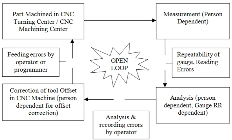
parameters measurement in CNC machine is primarily an open loop system. The checking is done by operator after completion of operation, which is not reliable. This is called OBQ (Operator based quality). The
In the proposed work, an end to end solution from auto measurement to analysis using an embedded system and feedback to the CNC machine using communication protocols, ther
Inspection system for a closed loop manufacturing system will be developed.
Copyright © 2015 Prathima et al. This is an open access article distributed under the Creative Commons Att distribution, and reproduction in any medium, provided the original work is properly cited.
INTRODUCTION
Over the years, machining systems have been developed with the ability to machine high-quality parts promptly, economically and precisely. CNC systems
the machining systems for more than half century and they have been playing an essential role in almost all aspects of manufacturing. Fundamentally, these systems are closed loop in their architectures, rigid in their configurations and complicated in their operations. Despite the machine being closed loop within itself, all the application
machine has not been effectively closed loop.
tool, the current programming standard is as per ISO 6983, using NC Codes. It describes merely low
such as machine tools actions and axis movements. The previously developed machining systems use STEP
the import for CAM modules hence CNC controllers still get only low-level information and was unidirectional. The newly developed STEP compliant NC standard ISO 14649 opened the way to transfer high-level information to CNC System.
*Corresponding author: Prathima, B.A.
Department of Electronics and Communication Engg., K.S.I.T., Bangalore, Karnataka, India.
ISSN: 0975-833X
Article History:
Received 18th June, 2015
Received in revised form 11th July, 2015
Accepted 19th August, 2015
Published online 30th September,2015
Citation:Prathima, B.A., Dr. Sudha, P.N. and Dr
loop manufacturing using embedded system”, International Journal of Current Research
Key words: CNC Machine Tool, NC code,
OBQ, SBQ,
Parts Per Million (PPM), Measurement Algorithms, Communication Protocols.
RESEARCH ARTICLE
PROPOSED METHODOLOGY FOR AUTO ERROR CORRECTION AND DETECTION FOR CLOSED LOOP
MANUFACTURING USING EMBEDDED SYSTEM
B. A.,
2Dr. Sudha, P. N. and
3Dr. Suresh, P.
Department of Electronics and Communication Engg., K.S.I.T., Bangalore, Karnataka, India
Department of Mechanical Engineering, K.S.I.T., Bangalore, Karnataka, India
ABSTRACT
The CNC machine tools are used to manufacture precision machined components. Generally the component profile & size to be achieved is programmed using NC Codes. Once the parts are produced, the operator will check whether the desired dimension is achieved or not. There are chances that due to the tool wear (predominantly) and other reasons like material non homoge insufficient coolant supply etc. (less predominantly) the produced parts are out of specified tolerance zone. By chance if the operator miss to check and correct the wear offsets, then there are chances that the few components get rejected during series of production. Dimensional and Geometrical parameters measurement in CNC machine is primarily an open loop system. The checking is done by operator after completion of operation, which is not reliable. This is called OBQ (Operator based quality). The requirement of the industry is to switch from the OBQ to SBQ (System Based Quality). In the proposed work, an end to end solution from auto measurement to analysis using an embedded system and feedback to the CNC machine using communication protocols, ther
Inspection system for a closed loop manufacturing system will be developed.
is an open access article distributed under the Creative Commons Attribution License, which distribution, and reproduction in any medium, provided the original work is properly cited.
Over the years, machining systems have been developed with quality parts promptly, economically and precisely. CNC systems have been around the machining systems for more than half century and they l role in almost all aspects of manufacturing. Fundamentally, these systems are closed loop in their architectures, rigid in their configurations and complicated in their operations. Despite the machine being closed loop within itself, all the applications around the machine has not been effectively closed loop. In the machine tool, the current programming standard is as per ISO 6983, using NC Codes. It describes merely low-level information such as machine tools actions and axis movements. The developed machining systems use STEP-NC file as the import for CAM modules hence CNC controllers still get level information and was unidirectional. The newly developed STEP compliant NC standard ISO 14649 opened the
formation to CNC System.
Department of Electronics and Communication Engg., K.S.I.T.,
This standard, also known as STEP
describe a wide range of information such as
measurement, feature placement, machining method, process parameter optimization and tool description etc.
2014). However all data can be fed in CAD level and available in the form of STEP NC through a post processor.
growing capabilities of CNC controllers, especially open architecture CNC (Yu et al., 2009
it possible to interpret STEP-NC directly without the help of post processor. These enhanced possibilities have made On Machine Inspection (OMI) systems which provide direct inspection in manufacturing and quality control, which was vital for automated production
Computer Aided Inspection Plan (CAIP) is an off line measurement system mainly developed for CMMs ordinate Measuring Machines). The concepts of CAIP are used in OMI. When compared to CMM, OMI was beneficial as the part was not disturbed from the machined location. Using STEP NC it was possible to measure parts on the machine itself using Touch Trigger Probes (
was not so much popular as the machining time was lost in measuring and machines accuracy was inferior when compared to that of CMM or any other exclusive measuring device.
International Journal of Current Research
Vol. 7, Issue, 09, pp.20519-20523, September, 2015
INTERNATIONAL
r. Suresh, P.M. 2015. “Proposed methodology for auto error correction and detection for closed
International Journal of Current Research, 7, (9), 20519-20523
PROPOSED METHODOLOGY FOR AUTO ERROR CORRECTION AND DETECTION FOR CLOSED LOOP
P. M.
Department of Electronics and Communication Engg., K.S.I.T., Bangalore, Karnataka, India
Department of Mechanical Engineering, K.S.I.T., Bangalore, Karnataka, India
The CNC machine tools are used to manufacture precision machined components. Generally the size to be achieved is programmed using NC Codes. Once the parts are produced, the operator will check whether the desired dimension is achieved or not. There are chances that due to the tool wear (predominantly) and other reasons like material non homogeneity, insufficient coolant supply etc. (less predominantly) the produced parts are out of specified tolerance zone. By chance if the operator miss to check and correct the wear offsets, then there are chances that ries of production. Dimensional and Geometrical parameters measurement in CNC machine is primarily an open loop system. The checking is done by operator after completion of operation, which is not reliable. This is called OBQ (Operator based requirement of the industry is to switch from the OBQ to SBQ (System Based Quality). In the proposed work, an end to end solution from auto measurement to analysis using an embedded system and feedback to the CNC machine using communication protocols, thereby making Auto Inspection system for a closed loop manufacturing system will be developed.
ribution License, which permits unrestricted use,
This standard, also known as STEP-NC, can be used to describe a wide range of information such as part geometry measurement, feature placement, machining method, process parameter optimization and tool description etc. (Po et al., . However all data can be fed in CAD level and available in the form of STEP NC through a post processor. The ever-growing capabilities of CNC controllers, especially open
2009) (Yuan et al., 2009), makes NC directly without the help of post processor. These enhanced possibilities have made
On-Inspection (OMI) systems which provide direct inspection in manufacturing and quality control, which was vital for automated production (Zhao et al., 2009).
Computer Aided Inspection Plan (CAIP) is an off line measurement system mainly developed for CMMs (Co-ordinate Measuring Machines). The concepts of CAIP are used in OMI. When compared to CMM, OMI was beneficial as the part was not disturbed from the machined location. Using possible to measure parts on the machine itself (Valino et al., 2009). But OMIs was not so much popular as the machining time was lost in measuring and machines accuracy was inferior when compared to that of CMM or any other exclusive measuring device.
INTERNATIONAL JOURNAL OF CURRENT RESEARCH
roposed methodology for auto error correction and detection for closed
The researchers intend to employ either invasive (touch type) or non-invasive (non touch type) sensors to measure feature parameters. Sensors like LVDT, Laser, Ultrasonic, LED, Photoelectric, CCD camera etc. are extensively and effectively used for such applications. A system consisting of smart sensors generally includes a direct connection of different kinds of physical sensors, and sensors that can be interfaced to a microcontroller, or a digital signal processor. Those smart sensors are adaptive and have memory of the past. Smart sensor boards include signal processing modules that are capable of amplitude transformation, linear compensation, digital reset to zero and digital filtering. Micro electro mechanical system and CMOS technologies can be integrated to provide smart sensors with better anti-interference ability (Feng et al., 2012).
The application on discussion requires variety of features with reference to their resolutions, linearity, measuring range, measuring cycle time, cost etc. Some efforts in the areas of measurements using above sensors are evidence in Flatness measurement using pressure sensor (Lan et al., 2011) and Automated Vision Inspection System for the Size Measurement of Work pieces (Lei et al., 2005). These efforts describe the methodology to use sensor, data collection, algorithm development to process the collected data, optimize the algorithms by comparison of the results and select the most appropriate methodology to measure the above said parameters. The techniques like edge detection, wavelet edge detection, diffuse reflective, regular reflective etc. are in practice to sense the parameter and convert them to data sets for further analysis and error detection. The algorithms enable the data collection and acquisition in such a way that the data set captured represents the net near shape of the feature parameter with minimum data loss and data deformation. Cooley–Tukey FFT Algorithm (Lan et al., 2011), Radix-2 Decimation-In-Time (DIT) Fast Fourier Transform (FFT), Discrete Fourier Transform (DFT), Simple Moving Average Algorithm (Lan et al., 2011) are commonly used algorithms for data processing.
Traditionally least squares algorithms are used for form tolerance assessment. Form tolerances like flatness, cylindricity, perpendicularity can be assessed using this algorithm. The proposed approach applies to a set of cases in order to validate the effectiveness and the robustness of the approach. The obtained results indicate that the proposed algorithm provides accurate and quick assessment (Prisco and Polini, 2010). The algorithms play a major and convenient role in the micron measurement in engineering metrology. To achieve implementation simplicity, computational efficiency and robustness of algorithms, the features like genetic algorithms, hierarchical algorithms are used.
Depending on the complexity of the profile or the surface form suitable algorithms are used. Form tolerances tends to become complex when compared to the geometrical tolerances. One or more algorithms were applied on the same parameter and an optimization technique was applied to obtain best fit result (Wen et al., 2006) (Zhu and Ding, 2003). The system on chip via field-programmable gate array (SoC-FPGA) technology has made the data acquisition requirements of the modern real time applications more sophisticated and affordable (Abdallah
et al., 2011).
The data acquisition system designed based on the above concepts do not depend on the expensive general purpose computer based or microcontroller based implementations. These can be designed just enough to manage the data in the said application. The collected accurate data of error was subjected to decision tree using an embedded system to evaluate the acceptance or rejection of the parts based on the error content (Edelmoser and Anselmi, 1996) (Mou et al., 1994) (Peckol, 2008).
Communication Protocols to communicate the error data back to the CNC system will enable the manufacturing system to move from Operator Based Quality to System Based Quality. This is a significant step towards closed loop manufacturing system. In the present scenario the open architecture CNC machines are able to communicate using digital data (Yu et al., 2009) (Yuan et al., 2009). The communication protocols to communicate with various types of CNC systems which are predominantly assisted by PLC (Dongkai et al., 2012) needs to be developed which can be a generic model of data transfer to any CNC System.
Abbreviations
CNC NC
Computer Numerical Control Numeric Control
OBQ Operator Based Quality SBQ
STEP CAM
System Based Quality
Standard for the Exchange of Product model data Computer Aided Manufacturing
CAIP CMM OMI PPM CCD LVDT LED FFT DIT DFT PLC SoC FPGA
Computer Aided Inspection Plan Coordinate Measuring Machine On Machine Inspection Parts Per Million Charge Coupled Device
Linear Variable Differential Transformer Light Emitting Device
Fast Fourier Transform Decimation-In-Time Discrete Fourier Transform Programmable Logic Controller System on Chip
Field Programmable Gate Array
Need for Closed Loop Manufacturing System
In mass production environment, the critical parameter of the given operation will be identified and the same will be subjected to inspection at the end of each cycle. However, other parameters, which are more stable in the process or less critical in nature, can be subjected to inspection in a particular frequency based on the standard sampling plans. The critical parameter needs special attention.
Manufacturing System. The rejection would be more severe in mass production environment, as operation time is less and several components can get rejected before incorporating the corrective action. Several manual controls are in practice to check the same such as set up approval, in-process checking, final inspection, on the job training etc. However, this area has remained as open loop and predominantly dependent on operator only. The industry norms for rejection is 0 to 500 PPM (parts per million) i.e. 0 to 0.05%. Depending on the process stability and capability, the rejection levels are around 2% – 3% (20000 to 30000 PPM) which is not acceptable. The requirement of the industry is to switch from the OBQ to SBQ. Fig. 2 shows the block diagram of Closed Loop Manufacturing System. The proposed research work will significantly reduce the PPM levels to achieve the industry norms.
MATERIALS AND METHODS
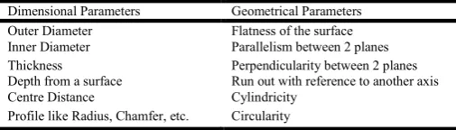
The various components produced may have one or more errors in the following parameter. Some of the major errors that can occur during production process are tabulated in Table 1. Not all the parameters are critical in a given component. Many would be achieved by process and hence may not require thorough checking. However, some key functional parameter would require checking after each cycle with corrections.
Step-1: Study of existing measurement methods
[image:3.595.106.508.257.500.2]Several methods of measurements are in practice in the industry. These are categorized as first principles, analog devices and digital devices.
[image:3.595.106.510.539.723.2]Fig. 1. Open Loop Manufacturing System
Table 1. Dimensional and Geometrical Parameters
Dimensional Parameters Geometrical Parameters
Outer Diameter Flatness of the surface
Inner Diameter Parallelism between 2 planes
Thickness Perpendicularity between 2 planes
Depth from a surface Run out with reference to another axis
Centre Distance Cylindricity
Profile like Radius, Chamfer, etc. Circularity
A fair understanding of the usage of various devices and their resolutions, hysteresis, parallax error possibilities are to be identified. The feature parameters could be dimensional or geometric in nature. Different methodologies are adopted to measure individual parameters.
Step-2: Selection of sensors
Based on the existing measurement methods, the most suitable replacement methodology to be selected using appropriate sensors. The sensor could be invasive or non invasive depending on the application. Measuring range, sensing object, resolution, linearity etc have to be important selection criteria to provide a similar feel of operation with better precision.
Step-3: Algorithm development
Based on the complexity of the measurement feature and the behavioural pattern on the sensor’s output, suitable algorithms will be developed to have most optimum results which can be scalable to a range of objects for measuring similar feature parameters. The results of the developed algorithms will be calibrated with the master value stored in an embedded system to validate and finalize the algorithm.
Step-4: Error detection
The measured value shall be compared with the mean value and the variation with reference to the total tolerance band will be detected. The decision algorithm will be devised to detect the errors and decide on the parts acceptance, rework and rejection using an embedded system.
Step-5: Auto Correction of error
The communication protocols will be developed to communicate with the CNC systems architecture. Many old generation CNC systems are with RS232 ports. However the latest CNC systems are with open architecture and are compatible with USB ports. The communication protocol should be able to feed the error back to the to the CNC system to make the whole system closed loop.
Conclusion
In an OBQ, the complete process is depending on the operator, which is not reliable and the rejection would be more severe. The requirement of the industry is to switch from the OBQ to SBQ. In the proposed work, a set of modern sensors are selected based on their capability to measure microns in various applications. The measurement algorithm will be developed to detect the error in its precise form.
An embedded system will acquire the error content, process and analyse with reference to the mean value. The detected error is communicated to the end machine using communication protocols. The proposed methodology helps in significantly reducing the rejection (PPM level) towards industry norms, hence minimizing the wastage of resources.
REFERENCES
Abdallah, M., Elkeelany, O. and Alouani, A.T. 2011. A low-cost stand alone multichannel data acquisition, monitoring, and archival system with on-chip signal preprocessing.
Instrumentation and Measurement, IEEE Transactions,
60(8), 2813 – 2827.
Dongkai, Q., Xiangyu, Y. and Jinxin, J. 2012. The application of PLC to CNC machine tools development, Proceedings of Third International Conference on Digital Manufacturing & Automation, 1213-1216.
Edelmoser, K. and Anselmi, C. 1996. Intelligent and free user configurable low cost data acquisition unit. Industrial Electronics, Control, and Instrumentation, Proceedings of IEEE IECON, 1301-1305.
Feng, A., Knieser, M., Rizkalla, M. and King, B. 2012. Embedded system for sensor communication and security. Information Security, IET journals, 6(2), 111-121.
Lan, J., Yu, S., Xu, L. and Chen, X. 2011. Control algorithm based on shape recognition. Cloud Computing and Intelligence Systems (CCIS), IEEE International
ConferenceProceedings, 559-563.
Lei, L., Zhou, X. and Pan, M. 2005. Automated vision inspection system for the size measurement of work pieces. Proceedings of Instrumentation and Measurement
Technology Conference Ottawa, Canada, 872-877.
Mou, J., Donmez, M.A. and Cetinkunt, S. 1994. Integrated error correction system for machine performance improvement. American Control Conference, 2914-2918. Peckol, J. K. 2008. Embedded Systems – A contemporary
Design Tool, John Weily India Pvt. Ltd.
Po, H., Hongya, F., Zhenyu, H. and Dedong, H. 2014. A closed loop and self-learning STEP-NC machining system, Proceedings of IEEE/ASME International Conference on Advanced Intelligent Mechatronics (AIM), 1598-1603. Prisco and Polini, W. 2010. Least squares assessment of
flatness, cylindricity and sphericity through surface classification based on continuous symmetry of geometric object, Proceedings of Journal of Manufacturing
Engineering, 5(3), 153-165.
Valino, G., Prado, Y., Rico, J.C. and Álvarez, B.J. 2009. Tool compensation by means of touch trigger probes in CNC turning, Proceedings of IEEE ,1-4.
Wen, X., Xia, Q. and Zhao, Y. 2006. An effective genetic algorithm for circularity error unified evaluation.
International Journal of Machine Tools and Manufacture,
46(14), 1770-1777.
Yu, D., Hu, Y., Xun W. X., Huang, Y. and Du, S. 2009. An open CNC system based on component technology, IEEE
Transaction on Automation Science and Engineering,
302-310.
technology, International Conference on Information
Technology and Computer Science, 224-228.
Zhao, F., Xu, X. and Xie, S. Q. 2009. Computer-aided inspection planning - The state of the art, Computers in Industry, 60(7), 453-466
Zhu, L. and Ding, H. 2003. Application of kinematic geometry to computational metrology: distance function based hierarchical algorithms for cylindricity evaluation.
International Journal of Machine Tools and Manufacture,
43(2), 203–215.