ISSN Online: 2151-4844 ISSN Print: 2151-481X
DOI: 10.4236/sgre.2018.98009 Aug. 30, 2018 127 Smart Grid and Renewable Energy
IEC 61850 SCL Validation Using UML Model in
Modern Digital Substation
Byungtae Jang, Alidu Abubakari, Namdae Kim
Power System Technology Group, Korea Electric Power Corporation, Daejeon, South Korea
Abstract
The IEC 61850 standard stipulates the Substation Configuration Description Language (SCL) file as a means to define the substation equipment, IED func-tion and also the communicafunc-tion mechanism for the substafunc-tion area network. The SCL is an eXtensible Markup Language (XML) based file which helps to describe the configuration of the substation Intelligent Electronic Devices (IED) including their associated functions. The SCL file is also configured to contain all IED capabilities including data model which is structured into ob-jects for easy descriptive modeling. The effective functioning of this SCL file relies on appropriate validation techniques which check the data model for errors due to non-conformity to the IEC 61850 standard. In this research, we extend the conventional SCL validation algorithm to develop a more ad-vanced validator which can validate the standard data model using the Uni-fied Modeling Language (UML). By using the Rule-based SCL validation tool, we implement validation test cases for a more comprehensive understanding of the various validation functionalities. It can be observed from the algo-rithm and the various implemented test cases that the proposed validation tool can improve SCL information validation and also help automation engi-neers to comprehend the IEC 61850 substation system architecture.
Keywords
IEC 61850, Substation Automation, IED, XML, UML, XMI, Schema, Rule-Based SCL Validation, Syntax, Semantic Data Model, SCL Editor
1. Introduction
Power systems are complex systems which electrically connect geographically dispersed equipment from the power plants to the transmission and distribution substations and finally end with the supply of electricity to the customer [1].
How to cite this paper: Jang, B.-T., Ab-ubakari, A. and Kim, N. (2018) IEC 61850 SCL Validation Using UML Model in Modern Digital Substation. Smart Grid and Renewable Energy, 9, 127-149.
https://doi.org/10.4236/sgre.2018.98009
Received: August 7, 2018 Accepted: August 27, 2018 Published: August 30, 2018
Copyright © 2018 by authors and Scientific Research Publishing Inc. This work is licensed under the Creative Commons Attribution International License (CC BY 4.0).
http://creativecommons.org/licenses/by/4.0/
DOI: 10.4236/sgre.2018.98009 128 Smart Grid and Renewable Energy Various devices and operating systems from power plants to consumers have been introduced and utilized depending on the characteristics of such equip-ment. “Stand Alone” devices based on traditional standards are highly depen-dent on the technology of the manufacturer. Therefore, it is very difficult to in-tegrate various devices into the complex system in order to implement them, and to be able to do that various types of interface technologies are required. Since the advent of Smart Grid technology, we have created a common standard through international standardization rather than the manufacturer-dependent technology, leading to the establishment of a system-oriented technology envi-ronment. In particular, the IEC 61850 international standard proposes commu-nication network and data standardization for the automation of power system [2] [3] [4] [5]. In IEC 61850 Edition 1.0, standardization was limited to the substations domain while IEC 61850 Edition 2.0 extends the automation to all areas of power system [6].
In order to standardize the substation data model, the devices operating in the power system are identified and their related data is classified into the property class [7]. For example, in the substation domain, a circuit breaker is used to quickly disconnect a fault section in the event of a fault in a system. The breaker is classified as Logical Node by XCBR and the data model name is specified. The detailed attributes are classified into Data Objects and Data Attributes, and data names are assigned. In this way, data model standardization work was carried out and a large amount of data was processed in a text-based table format. However, the use of text-based tables has not been able to prevent duplication causing inconsistencies in the standardization of large amounts of data. Espe-cially as the application domain of power system is expanded. When the IEC 61850 Edition 2.0 document was developed, the number of Logical Nodes de-fined in IEC 61850 Edition 1.0 has increased rapidly from 90 to 300 (over 200%). To address this challenge, the IEC 61850 International Standardization Work Group, standardized the data models using UML (Unified Modeling Language) to improve upon the manual text-based table formatting of the standard data model [8].
DOI: 10.4236/sgre.2018.98009 129 Smart Grid and Renewable Energy using the metamodeling technique. Section III then elaborates on the concept of data model validation in IEC 61850. This includes a discussion on the conven-tional SCL validation algorithm and a detail presentation on the proposed UML based SCL data model validator. We present on the practical implementation procedure, main features of the tool, test scenario, actual implementation, error checking mechanism in section IV. The advantages of the proposed validation are also discussed in Section IV and in Section V we present the conclusion.
Literature Review
Various researches have been conducted on substation configuration and SCL since the conception of Substation Automation (SA) System. Most existing re-search focuses on the design of vendor independent configuration tool for SCL including [9] and [10]. Research in [9] studied the use of the SCL in describing IEC 61850 models. The paper investigated the application of SCL in the descrip-tion of substadescrip-tion domain objects and models. The authors also studied on the differences and similarities between the various SCL files and also constraints in practical application of the SCL in a digital substation. Research in [10] imple-mented a visual designer to facilitate the engineering of SCL files without the need for knowing the details of the underlying XML syntax. The researchers de-veloped a graphic model approach using the UML model to make it simple for engineers to configure the SCL file. Research work by [11] also focused on the development of fully graphical XML-based SCL configurator by taking SCL ob-ject model, visual representation of substation elements into consideration. Their work proved the possibility of integrating the XML-based Scalable Vector Graphics (SVG) into SCL visual representation. The work in [12] focused on the use of SQL server to design and implement an SCL configurator. The basic idea is the transformation of data into XML format using a relative method.
DOI: 10.4236/sgre.2018.98009 130 Smart Grid and Renewable Energy hyperlink between error type and line of SCL XML file where it occurred. These conventional SCL tools operate using the “black-box” concept whereby the user does not usually understand what the error means and how to correct it. Some tools are also integrated into manufacture-specific SCL configuration tools making it difficult to use without the right expertise. There is the need to im-plement manufacturer independent validator which verifies the SCL file beyond schema. Our previous work in [18], gives an outlook on the concept of SCL va-lidation and also the aspects to be validated. We presented a simple and com-prehensive engineering tool design which would facilitate the development of an intelligent substation system via a thorough SCL verification process. This work is an extension of the work in [18] where we explore the architecture and im-plementation of the SCL data verification component of the tool.
2. IEC 61850 Metadata Architecture
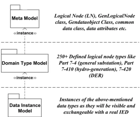
Metadata refers to the used to describe another related data. The IEC 61850 standard utilizes the metamodeling approach to conceptualize the domain data type model which defines the semantics of all the data communicates in the substation. Thus the semantics of the data is modelled by metadata which are parts of the metamodel [19]. The IEC 61850 metamodeling which refers to the abstract description of data using data can be seen in Figure 1. The metamodel abstracts the concept of Logical node and the data attributes which are not ap-plication-domain specific. The Domain Type Model abstracts data model de-fined for substation specific logical nodes and data attributes. The data instance model represents the instance of the domain data type used in the IED. The ad-vantage of using the data metamodel is that it helps manage the large amount of power substation data and data integration [19].
2.1. Hierarchical IEC 61850 Metadata Modeling Technique
DOI: 10.4236/sgre.2018.98009 131 Smart Grid and Renewable Energy Figure 1. IEC 61850 Meta modelling architecture.
Figure 2. Hierarchical data modeling case for IEC 61850.
A group of LN (LLNO, LPHD, and XCBR) is used to build a logical device (LD) while a group of LD (ViPAM5000PRT, ViPAM5000MET and Vi-PAM5000CTL) is implemented as the physical device or the IED. The XCBR LN decomposes into various data objects including Mode (Mod), Beh (Behavior), NamePlt (Nameplate), Loc (local Control behavior), OpCnt (Operation Coun-ter) and Pos (switch Position). The switch position “Pos” data object is also made up of groups of data attributes including control data attributes, substitu-tion data attributes and others like configurasubstitu-tion, descripsubstitu-tion and extension data attributes. The “Pos” data object in Figure 2, has about four (4) data attributes for XCBR LN. The data attribute “Pos.ctlval” is used for controllable
informa-Physical device
Logical
Device
Logical
Node
Data
Object
Data
Attribute
[image:5.595.264.479.300.544.2]DOI: 10.4236/sgre.2018.98009 132 Smart Grid and Renewable Energy tion like setting circuit breaker “on” or “off” while “Pos.stVal” is used to com-municate the condition (status). According to the standard, the condition of the circuit breaker can be “on”, “off”, “bad-state” and “intermediate-state”. The “Pos.q” is used as an indication of the validity of the status value while “Pos.t” represents the time of the last change of the status value. The position switch (Pos) is a Double Point Controllable (DPC) Common Data Class (CDC).
2.2. Representation of IEC 61850 Metadata in the Standard
The hierarchical meta model architecture of the IEC 61850 data model is represented using tables in both edition 1 and 2 of the standard. An example of such metamodeling of substation circuit breaker data is shown in Figure 3.
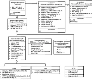
As can be observed from Figure 3, the Logical Node (LN) Class, Data Object (DO), Data Attributes (DA), Functional Constraints (FC), data type and the presence conditions are defined by the IEC 61850 in tables [21] [22]. The IEC 61850 edition 1 uses text-based description of the data and the meta of the data model semantics and these are structured by means of table. Sometimes, these tables also reference other tables in other documents without explicit navigation links between them. This makes the tabular-approach to data model structuring very complicated with over 150 tables scattered within 600 pages of 5 different IEC 61850 standards. To address this problem created by too many text-based data model description, the UML model has been proposed [19]. The UML model allows for consistent data modelling across multiple application using the metamodeling approach while establishing explicit relationships though inhe-ritance properties [23] [24]. It also promotes processability through the use of computer-aided solutions to automatically generate codes, check consistency, and also generate text documents. An example of the UML model for the circuit breaker is shown in Figure 4.
Modeling in UML allows the use of cardinality and optionality instead of mul-tiple graphical symbols. This eases the complications in the design process and also the model comprehension. Ambiguities in the standard definition can be identified easily due to the reduction in the number of tables used for data type descriptions. Also, ambiguity in standard interpretation by device manufacturers and researchers can be mitigated. The use of the UML model for IEC 61850 data description also ensures comprehension of the standard data model thereby promoting effective communication between software architects and domain engineers.
3. Overview of SCL in IEC 61850 Digital Substation
DOI: 10.4236/sgre.2018.98009 133 Smart Grid and Renewable Energy Figure 3. Hierarchical data modeling case for IEC 61850.
Figure 4. IEC 61850 UML diagram for circuit breaker (XCBR).
network. Description of the IED includes its configuration logic nodes, data and the data attributes. SCL simplifies and automates the configuration of the digital substation system, thus increasing the flexibility of information exchange be-tween SA systems and/or devices.
Part 7-4
Part 7-3
Logical Node Class
Presence Condition
Functional Constraints Data
Objects
Common Data Class
Data Types List of
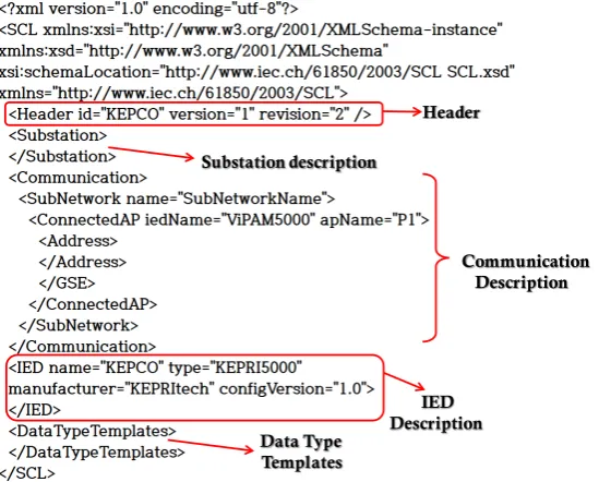
[image:7.595.211.532.354.634.2]DOI: 10.4236/sgre.2018.98009 134 Smart Grid and Renewable Energy This reduces the workload, the rate of error occurrence and thus increase overall power efficiency. The complete description of the SA System as can be seen in Figure 5 occurs under five (5) elements in the SCL file. These are the header, substation, IED, Communication system and DataType Templates. The header element includes the identification of the SCL file, its version and revi-sion information and options for mapping names to signals. The substation ele-ment describes the functional architecture of the substation including the pri-mary devices and the associated electrical connects. The IED element describes the IED configuration including the logical devices and its associated logical nodes and access points. It defines the IED communication services, its logical node type, instantiated data and the configuration values. The communication element defines the means of connections between logical nodes via subnet-works and access points. Finally, the datatype template defines the instantiable logical node type, data object type, data attribute type and enumerate data type for each logical device associated [26].
3.1. General Procedure for SCL Engineering
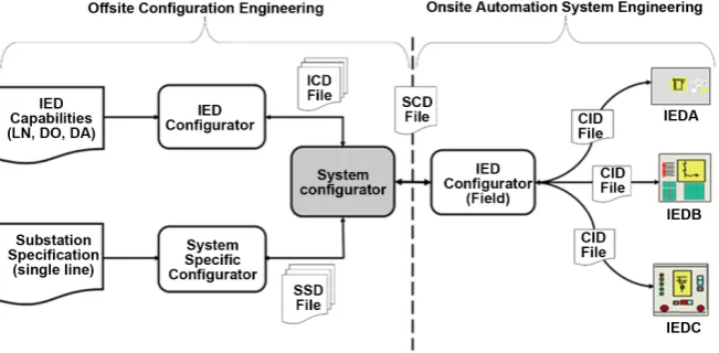
[image:8.595.242.517.483.704.2]To make the content easier to understand and use, the IEC 61850 standard de-fines six (6) files each containing different information for different applications in the engineering process. These files are the IED Capability Description (ICD), System Specification Description (SSD), System Configuration Description (SCD), the Configured IED Description (CID), the Instantiated IED Description (IID) and the System Exchange Description (SED). The ICD file contains the information concerning the IED capabilities, the system description, and the de-fault factory-set communication description of the IED. The SSD describes the substation architecture using the single line diagram and thus helps dictate the
Figure 5. The various sections of a typical SCL file.
Header
Substation description
Communication Description
Data Type Templates
DOI: 10.4236/sgre.2018.98009 135 Smart Grid and Renewable Energy required logical nodes for the SA system. The SCD file contains specifications of the substation architecture with their allocated logical nodes and communica-tion services and interface. The CID file is used to configure a particular vendor IED in the SA project. The second edition defines the IID file which contains the information of an already pre-configured instance of an IED including project addresses and datasets. This can be used to configure a new IED’s ICD file espe-cially in the case of substation expansion. To identify the interface between dif-ferent projects, the SED file can be used. The substation specification design is loaded from its database into the system specification configurator to produce a complete single-line description of the substation in the form of the .SSD file. The ICD files are then generated by loading the IED capabilities from its asso-ciated Database into the manufacturer-specific IED Configurator. The SSD files and the ICD files are imported into the vendor-independent system configura-tion tool which generates the SCD file. After the generaconfigura-tion of the SCD file, all IEDs would be associated with specific field equipment and independent processes function. This implies all logical devices, logical nodes and data objects are bound to real-time processes and functions. Lastly, the CID files are created and imported to each IED from the vendor-specific IED configurator [25]. The complete engineering process for the various SCL files is shown in Figure 6.
3.2. Importance of SCL in Digital Substation
[image:9.595.209.535.548.708.2]The SCL file is a critical element in the complete life-cycle of an SA system in-cluding the design, commissioning, testing and evaluation etc. In order to im-plement a simple and easy technique for the exchange of data between engi-neering tools at various levels of the SA system, it is important to design a single file format for all devices. This is achieved using the SCL file as it can in its sign process take into account the different and sometimes proprietary data de-finitions and data format. The SCL file contains the static description of an IED which is IEC 61850 compatible. It helps to describe the capabilities of the IED device. It can also serve as a means to document the complete system for easy
DOI: 10.4236/sgre.2018.98009 136 Smart Grid and Renewable Energy analysis especially during extensions and retrofitting. By developing a database library of substation configuration in the form of single line diagram, it is possi-ble to easily adjust the substation system design to check for compatibility and performance measurement before actual implementation. The SCL file can be used to generate and analyze the semantic model of the IED under consideration with or without reference to manufacturers’ documentation.
The SCL file can also be used to retrieve a section of the IED using the self-description capability of the IED for verification against the standard. It can serve as a means to create a virtual IED on a computer using the appropriate si-mulation tools. It can be used in conjunction with the appropriate sisi-mulation tools to test various communication scenarios and techniques which cannot be implemented physically due to the cost involved.
3.3. The Concept of SCL Validation
SCL validation can be defined as the tools and techniques required to check the conformity of an IED SCL file to the IEC 61850 standard to enable interoperable operation with other devices in the modern digital substation. It is a testing tool designed to enable the verification of the SCL file both syntactically and seman-tically in accordance with IEC 61850 standard part 6. In order to perform this verification, the validation tool is required to extract the schema (syntax) and the data model of the SCL file. The ideal SCL validator is also required to easily im-port all related SCL files including SCD, SSD, SED, CID, IID and ICD while providing a database of the standard data model for comparison. Multivendor IEDs are expected to communicate and work successfully in a plug and play fa-shion if their SCL files are successfully validated [27]. Therefore, there is the need to design an effective SCL validation tool which is the main focus of this research paper. The operational method of the SCL validator is illustrated in Figure 7 based on discussions in [16]. The comparative analyzer in simple terms compares the object model of the SCL file to the standard rules in IEC 61850. Any inconsistency results in a failed output which would alert the engineer of a possible interoperability problem before the actual implementation and com-missioning of the IEDs. This would prevent the future malfunctioning of the SA system.
4. Design Concept for IEC 61850 Data Model Validation
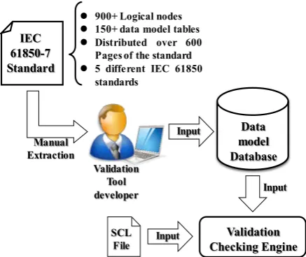
4.1. Conventional SCL Tool Design
The existing architecture for SCL validation tool is shown in Figure 8. The data model database is extracted manually from the IEC 61850 standard (typically from part 7). This method of developing the data model DB is prone to errors due to human involvement.
DOI: 10.4236/sgre.2018.98009 137 Smart Grid and Renewable Energy Figure 7. Illustration of the method of execution of an SCL validator.
Figure 8. Manual extraction of the data model from the IEC 61850 database.
types and data models due to the “flatness” of the database. Basically this ap-proach is inefficient and there is a need to develop a new apap-proach to validate the data model of the SCL file under test.
4.2. Proposed SCL Validation Tool Design
The algorithm of the proposed SCL validation tool which uses the UML database is as shown in Figure 9. The UML model is imported into the validation system where it is converted to XMI and to the relational database for easy access. The guide DB is a database of all the pre-defined validation rules. The test engineer can select multiple rules for the validation. The validation engine is responsible for extracting the SCL data model, and ensuring a thorough check of the data using the validation rule based on the data extracted from the UML model by way of XMI database. In case an error is discovered during the validation, an
IEC 61850-7 Standard
Validation Checking Engine
SCL
File Input
Input Manual
Extraction
Validation Tool
developer Input
Data model Database
900+ Logical nodes 150+ data model tables Distributed over 600
Pagesof the standard 5 different IEC 61850
[image:11.595.265.484.292.476.2]DOI: 10.4236/sgre.2018.98009 138 Smart Grid and Renewable Energy Figure 9. Proposed Algorithm for the IEC 61850 data model
validation.
error report is submitted to the test engineer for further evaluation and correc-tion using the SCL edit engine.
UML Transformation to Database
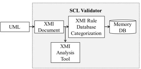
The SCL validation system imports the XMI (XML Metadata Interchange) from the UML file (.eap) in order to generate the IEC 61850 data model database re-quired for the SCL validation. The process is illustrated in Figure 10.
This transformation from UML to XMI is enabled automatically by the soft-ware-based model UML driven compiler like the Sparx Enterprise architecture software. The UML model describes objects using classes, attributes, associa-tions, actors, messages, packages, collaboraassocia-tions, states and other concepts stan-dardized in the UML language while the XMI standard defines the algorithm for use in the generation of metamodel vocabulary using XML tags. This implies that the XMI uses XML classes, attributes and associations to define a complete XML vocabulary for UML. The XMI analysis tool is responsible for ensuring the syntactic completeness of the exported XMI file utilizing a fixed set of declara-tion used by all XMI documents. It also uses the standard IEC 61850 hierarchical data structure to extract the XMI database by grouping all data under specific categories.
An example of the XMI database categorization is shown in Figure 11. This is then exported to the SCL validator memory database where the data is stored using relational database architecture. Since the memory database is relational, it contains tables and columns for each XML-tag data which in this case represents the XMI database categorization shown in Figure 11. The use of the UML model for IEC 61850 data modelling helps achieve data consistency through maintain-ing relationship between the various data types. This relationship, which is key to establishing data consistency, is also maintained through the use of the
UML
Validation Engine
Select Validation Rule
Start Validation
Has Error?
Generate Error Report
End Convert
XMI
Guide DB Memory
DB
SCL Edit Engine
SCL
Submit Error Report Modify
DOI: 10.4236/sgre.2018.98009 139 Smart Grid and Renewable Energy Figure 10. Proposed Algorithm for the IEC 61850 data
mod-el validation.
Figure 11. Categories for grouping the UML data model in-formation extracted from XMI.
relational database for the SCL validator memory database. This is because the relational database architecture separates the data into its different constituents while still maintaining relationship between them.
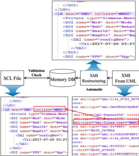
An example is seen in Figure 12 the XMI analysis tool extracts the XMI data-base by grouping all IEC 61850 Logical Node Groups, all standard IEC 61850 Logical Nodes, Common data classes, Common data class groups, Functionally Constraint Data Attributes (FCDA), all IEC 61850 Data Attribute Types (DA-Types), IEC 61850 Data Types (DA’s), Functional Constraints (FC), Presence Condition, Trigger Options and IEC 61850 Namespace. Based on a comparison between Figure 12 and Figure 13 we can observe the main difference between our proposed tool and conventional SCL validation tools respectively. For con-ventional tools, the database is manually generated from part 7 of the IEC 61850 standard making it too laborious and also prone to errors. Our proposed tool generates the data model database automatically and can be help automate the SCL validation process. This does not only minimize human-prone errors but also simplifies the use of the tool for substation automation or test engineers.
SCL Validator
[image:13.595.265.483.230.438.2]DOI: 10.4236/sgre.2018.98009 140 Smart Grid and Renewable Energy Figure 12. Proposed Algorithm for the IEC 61850 data model
validation.
Figure 13. A practical illustration of the conventional SCL va-lidation method.
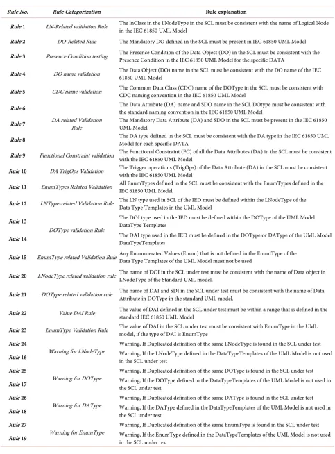
4.3. Generating the SCL Validation Rule
Table 1 provides a list of the pre-defined validation rules utilized in the devel-opment of the proposed data model validator. These standardized rules are gen-erated from the semantic requirements as specified in the UML data model. These rules are fixed and are ideally updated with each revision of the validation software. The main reason for adopting the rule-based approach is able to the test engineer utilizes the error message when debugging errors in the SCL file. The error message contains a summary which consists of an interactive hyper-link between the validation rule, the error type and the XML-based SCL line where the error occurred. This is in contrast to available validation tools which uses the “black-box method”, essentially keeping all error related information
SCL File
Automatic
XMI From UML Memory DB
Validation
Check XMI
Restructuring
SCL File Rule DB Manual Manual DB Input data
[image:14.595.262.494.378.519.2]DOI: 10.4236/sgre.2018.98009 141 Smart Grid and Renewable Energy Table 1. The list of rules created for SCL validation.
Rule No. Rule Categorization Rule explanation
Rule 1 LN-Related validation Rule The lnClass in the LNodeType in the SCL must be consistent with the name of Logical Node in the IEC 61850 UML Model
Rule 2 DO-Related Rule The Mandatory DO defined in the SCL must be present in IEC 61850 UML Model
Rule 3 Presence Condition testing The Presence Condition of the Data Object (DO) in the SCL must be consistent with the Presence Condition in the IEC 61850 UML Model for the specific DATA
Rule 4 DO name validation The Data Object (DO) name in the SCL must be consistent with the DO name of the IEC 61850 UML Model
Rule 5 CDC name validation The Common Data Class (CDC) name of the DOType in the SCL must be consistent with CDC naming convention in the IEC 61850 UML Model
Rule 6
DA related Validation Rule
The Data Attribute (DA) name and SDO name in the SCL DOtype must be consistent with the standard naming convention in the IEC 61850 UML Model
Rule 7 The Mandatory Data Attribute (DA) and SDO in the SCL must be present in the IEC 61850 UML Model
Rule 8 The DA type defined in the SCL must be consistent with the DA type in the IEC 61850 UML Model for each specific DATA
Rule 9 Functional Constraint validation The Functional Constraint (FC) of all the Data Attributes (DA) in the SCL must be consistent with the IEC 61850 UML Model
Rule 10 DA TrigOps Validation The Trigger operations (TrigOps) of the Data Attribute (DA) in the SCL must be consistent with the IEC 61850 UML Model
Rule 11 EnumTypes Related Validation All EnumTypes defined in the SCL must be consistent with the EnumTypes defined in the IEC 61850 UML Model
Rule 12 LNType-related Validation Rule The LN type used in SCL of the IED must be defined within the LNodeType of the Data Type Templates in the UML Model
Rule 13
DOType validation Rule
The DOI type used in the IED must be defined within the DOType of the UML Model DataType Templates
Rule 14 The DAI type used in the IED must be defined in the DOType or DAType of the UML Model DataTypeTemplates
Rule 15 EnumType related Validation Rule Any Enummerated Values (Enum) that is not defined in the EnumType of the Data Type Templates of the UML Model must not be used
Rule 20 LNodeType related validation rule The name of DOI in the SCL under test must be consistent with the name of Data object in LNodeType of the Standard UML model.
Rule 21 DOType related validation rule The name of DAI and SDI in the SCL under test must be consistent with the name of Data Attribute in DOType in the standard UML model.
Rule 22 Value DAI Rule The value of DAI defined in the SCL under test must be within a range that is defined in the standard IEC 61850 UML Model
Rule 23 EnumType Validation Rule The value of DAI in the SCL under test must be consistent with EnumType in the UML model, if the type of DAI is EnumType
Rule 24
Warning for LNodeType Warning, If Duplicated definition of the same LNodeType is found in the SCL under test Rule 16 Warning, If the LNodeType defined in the DataTypeTemplates of the UML Model is not used in the SCL under test
Rule 25
Warning for DOType Warning, If Duplicated definition of the same DOType is found in the SCL under test Rule 17 Warning, If the DOType defined in the DataTypeTemplates of the UML Model is not used in the SCL under test
Rule 26
Warning for DAType Warning, If Duplicated definition of the same DAType is found in the SCL under test Rule 18 Warning, If the DAType defined in the DataTypeTemplates of the UML Model is not used in the SCL under test
Rule 27
DOI: 10.4236/sgre.2018.98009 142 Smart Grid and Renewable Energy hidden except for the XML-based SCL line where the error occurred. This might not be enough for an informed error correction and this is one of the problems our proposed tool can mitigate. Also although, rules are fixed and are ideally updated with each revision of the validation software, we are working to incor-porate an user-defined rule generation functionality in the future in order to ensure flexibility.
5. Practical Implementation of IEC 61850 Data Model
5.1. Main Features of UML-Based SCL Validation S/W
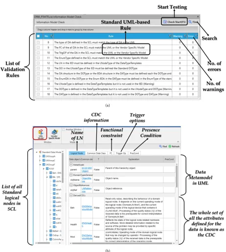
Figure 14(a) shows the pre-defined UML based validation test rule. The rules are generated based on the semantic specifications of IEC 61850. By selecting a specific rule from the list of validation rules, a specific aspect of the SCL data model is checked for errors using the UML memory database. The display tech-nique used in Figure 14(b) helps the test engineer to understand the various standard data objects. This is implemented using the standard UML model of IEC 61850-7 as explained earlier. It shows the detailed information about the data objects in the SCL file thereby making it easy for test engineers to under-stand the relationship between different logical nodes and data objects without the need to constantly refer to the standard as it is quite voluminous.
5.2. Test Case for UML-Based SCL File Validation
5.2.1. SCL Validation Test scenario
The scenario under consideration is to test for the implementation of the Logical node type element according to the IEC 61850-7 standard. The LNodeTypes are provided under the DataType template section of the SCL file. It describes the instantiation of a specific logical node. Thus, it contains information including the data objects (DO), the various data attributes (DA) and the configuration default parameters. The data object in an LNodeType becomes a Data Object In-stance (DOI) in the corresponding logical node. As stated in Table 2 and in ac-cordance with part 7 of the IEC 61850 standard the following are the attributes of the LNodeType element.
These attributes can be observed in the schema extract defined in part 6 of the IEC 61850, illustrated in Figure 15.
To implement a tractable test case for the data model validation, the SCL file is edited as can be seen in Figure 16.
The wrong Inclass (XCBR is witched for XSWI) and DOType descriptions are provided for the XCBR logical node case. Figure 17 presents the validation rules implemented to test the above-mentioned error scenario in the SCL file.
5.2.2. Test Results and SCL File Editing
DOI: 10.4236/sgre.2018.98009 143 Smart Grid and Renewable Energy Table 2. Example of attributes of LNodeType element for testing.
Element Explanation
id The identification tag for the LNodeType in the SCL file InClass The logical node base class as defined in the IEC 61850-7-3 DOname The data object name as defined in IEC 61850-7-4
DOType The data object type which references the id of the DOType definition.
(a)
(b)
Figure 14. (a) Section of the proposed Data model validation rules; (b) Standard data model extracted from the SCL.
List of Validation
Rules
Start Testing
Search
No. of errors
No. of warnings Standard UML-based
Rule
List of all Standard logical nodes in
SCL
Name of LN
CDC information
Functional constraint
Trigger options
Presence Condition
The whole set of all the attributes defined for the data is known as
the CDC Data Metamodel
[image:17.595.77.540.183.700.2]DOI: 10.4236/sgre.2018.98009 144 Smart Grid and Renewable Energy Figure 15. Schema extract for the LNodeType element [25].
[image:18.595.184.539.516.708.2]Figure 16. Extract of SCL (under test) XCBR LNodeType da-ta for testing.
Figure 17. Selected Validation rules for SCL (XCBR LNodeType) data testing.
Figure 18. Results for the data model validation. Standard
data model validation
DOI: 10.4236/sgre.2018.98009 145 Smart Grid and Renewable Energy warning. It should be noted that warnings usually do not require debugging as much as the errors do. It can be observed that the error occurred in line 427 of the SCL file, where the initially edit was made. The wrong LNodeType configu-ration goes against the UML model rule which stipulates that “all mandatory DO defined in the UML model must be present in the SCL”. The final stage of the validation process is checking editing the SCL file in case of errors.
By selecting the error in the error log, the test engineer can edit the SCL file to achieve consistency with the standard. After editing the SCL file as shown in Figure 19, it is recommended to run a new test to validate the changes and to establish that the SCL file under test has no errors which can affect communica-tion in the practical substacommunica-tion scenario.
5.3. Merits of the Advanced SCL Validation Tool
There are several benefits of the above proposed SCL validation tool. In the first instance, the proposed data model validation of the SCL file can check the stan-dard data model using the UML model. The stanstan-dard data model is quite large and described using tables in several parts of the IEC 61850 standard. This makes tracking, understanding and validating the SCL file for data model related errors quite difficult for the test engineer. With the use of the UML model is quite comprehensive making it easier for the test engineer to implement accu-rate validation of the SCL file. The proposed validation tool for IEC 61850 SCL files employs the rule-based validation data model validation. For most conven-tional validation tools, the validation rules are not shown in the user interface and therefore it is difficult to understand the main reason behind an error. The rule-based validation makes it easy to understand the various aspects of the SCL required for validation. In case of an error, the test engineer can easily identify the cause of the error. It is also easy to directly debug the SCL file using the error guide without the need for third party XML editors. Our proposed algorithm is easy to use because it implements an automated checking process without the need of consistent check up by the test engineer which can cause lots of delay. The test process is top-bottom validation with the results listing out all the test errors while in the conventional validation case, each error causes the test to stop so that the test engineer can correct the error.
6. Conclusions
DOI: 10.4236/sgre.2018.98009 146 Smart Grid and Renewable Energy Figure 19. Illustration of the debugging process used to edit the SCL file.
In this paper, we propose a new test technique that can detect and correct the use and conformance of the standard data model of the multiple devices from different vendors during the digital substation engineering process when the various IEC 61850-based IEDs are being installed in the field of the power grid system. We have also demonstrated the detailed implementation of the proposed algorithm using an SCL validation developed by KEPCO. The proposed SCL lidation tool can present the substation engineer with the ability to separately va-lidate both the standard data model.
Our proposed tool is unique due to the fact that it is equipped with both the error guide and the rule guide which serves as a means to fully understand and debug errors associated with non-standard data model with the use of the SCL editor. The error guide also known as the SCL editor guide helps the test engi-neer to successfully align an SCL validation error to the validation rule and the corresponding XML line where the error occurred. This will help to solve inte-roperability problems which occur in practical SA systems by ensuring the syn-tactic and semantic correctness of the multi-vendor SCL files.
Future research would focus on improving the proposed validation tool by implementing other validation techniques including flexible user defined rule, vendor specific data extension validation and schema based validation.
Finally, although the use of the relational database model is quite flexible and it is capable of removing all redundancies and thereby ambiguities from the data stored, it has some strong drawbacks like its inability to support schema evolu-tion and also some weakness as a result of mismatches between the object oriented and relational database world. We therefore hope to use non-relational database in the future in order to benefit fully from the UML Model.
In the future, it is expected that the SCL file would serve as the sole configura-tion file for all the various domain of the electrical power system including dis-tribution automation, renewable energy, vehicle-to-grid etc. Therefore, to ensure interoperability in modern digital substation automation systems, our proposed SCL validator is required.
Conflicts of Interest
DOI: 10.4236/sgre.2018.98009 147 Smart Grid and Renewable Energy
References
[1] Pagani, G.A. and Aiello, M. (2013) The Power Grid as a Complex Network: A Sur-vey. Physica A: Statistical Mechanics and Its Applications, 392, 2688-2700.
https://doi.org/10.1016/j.physa.2013.01.023
[2] Roostaee, S., Hooshmand, R. and Ataei, M. (2011) Substation Automation System Using IEC 61850. Proceedings of the 5th International Power Engineering and Op-timization Conference, Shah Alam, Selangor, 6-7 June 2011, 393-397.
[3] Brand, K.P. and Janssen, M. (2005) The Specification of IEC 61850 Based Substation Automation Systems. Paper Presented at the DistribuTech 2005, San Diego, 25-27 January 2005, 8 p.
https://library.e.abb.com/public/b0dc46b17050d26bc125705a004de6d5/Brand_Janss
en_DistribuTech2005.pdf
[4] Adamiak, M., Baigent, D. and Mackiewicz, R. IEC 61850 Communication Networks and Systems in Substations: An Overview for Users.
http://www.gegridsolutions.com/multilin/journals/issues/spring09/iec61850.pdf
[5] Mackiewicz, R.E. (2006) Overview of IEC 61850 and Benefits. Proceedings of the IEEE/PES Transmission and Distribution Conference and Exhibition, Dallas, TX, 21-24 May 2006, 376-383. https://doi.org/10.1109/TDC.2006.1668522
[6] Wagh, K.S. and More, A. (2015) Comparative Analysis of IEC 61850 Edition-I and II Standards for Substation Automation. Proceedings of the 2015 IEEE International Conference on Computational Intelligence and Computing Research (ICCIC), Ma-durai, 10-12 December 2015, 1-6. https://doi.org/10.1109/ICCIC.2015.7435756
[7] Ozansoy, R., Zayegh, A. and Kalam, A. (2009) Object Modeling of Data and Data-Sets in the International Standard IEC 61850. IEEE Transactions on Power Deli-very, 24, 1140-1147. https://doi.org/10.1109/TPWRD.2008.2005658
[8] Marcadet and Lambert, E. (2016) RiseClipse: Why Working at the Model Level Is Better for Validating Data Conforming to IEC Standards. Proceedings of the 2016
Power Systems Computation Conference (PSCC), Genoa, 20-24 June 2016, 1-7. [9] Peng, X., Liang, Y.C., Luo, Z.P., Pan, F.L. and Li, L. (2016) Analyses and
Compari-sons of SCL Files in Substation Configurator. Proceedings of the 3rd International Conference on Systems and Informatics (ICSAI),Shanghai, 19-21 November 2016, 297-300.
[10] Huo, Z.H., Zhang, L.M. and Zhang, Z.X. (2008) Research on Graphics Model De-sign for IEC61850 SCL Visual Configuration. Proceedings of IEEE Pacific-Asia Workshop on Computational Intelligence and Industrial Application, Wuhan, 19-20 December 2008, 700-704. https://doi.org/10.1109/PACIIA.2008.42
[11] Pan, Y., Sun, K.H. and Ma, L.J. (2012) Design and Implementation of Visual SCL Configurator. Proceedings of the International Conference on Automatic Control and Artificial Intelligence, Xiamen, 3-5 March 2012, 782-785.
[12] Beil, L. and Lian-shunl, M. (2006) To Realize the SCL Configurator of IEC6 1850 Based on Relative Model. Proceedings of the International Conference on Power System Technology, Chongqing, 22-26 October 2006, 1-7.
https://doi.org/10.1109/ICPST.2006.321870
[13] Yang, Y., et al. (2014) Comparison Method for Differentiation of IEC 61850 Based Substation Configuration Files. Proceedings of the International Conference on Power System Technology,Chengdu, 20-22 October 2014, 1796-1801.
https://doi.org/10.1109/POWERCON.2014.6993635
DOI: 10.4236/sgre.2018.98009 148 Smart Grid and Renewable Energy
the Substation Configuration Language of IEC 61850 to ArchiMate. Proceedings of the 14th IEEE International Enterprise Distributed Object Computing Conference Workshops,Vitoria, 25-29 October 2010, 60-68.
https://doi.org/10.1109/EDOCW.2010.35
[15] Hou, S.Z., Liu, W. and Kong, F.Y. (2013) IEC61850 Gateway SCL Configuration Document Research. Proceedings of the 3rd International Conference on Intelligent System Design and Engineering Applications, Hong Kong, 16-18 January 2013, 824-831. https://doi.org/10.1109/ISDEA.2012.196
[16] Vetter, C., Frei, C. and Obrist, M. (2008) Validating a Standardized Configuration Description. U.S Patent 8156061B2.
[17] DNV GL, UniCA SCL (2017) Checker Version 3.29.
[18] Jang, B.-T., Alidu A. and Kim, N. (2017) Design of an Algorithm for the Validation of SCL in Digital Substations. KEPCO Journal on Electric Power and Energy, 3, 89-97.
[19] Kostic, T., Preiss, O. and Frei, C. (2005) Understanding and Using the IEC 61850: A Case for Meta-Modelling. Computer Standards & Interfaces, 27, 679-695.
[20] Zhu, Y.L., Wang, D.W., Wang, Y. and Zhao, W.Q. (2009) Study on Interoperable Exchange of IEC 61850 Data Model. Proceedings of the 4th IEEE Conference on Industrial Electronics and Applications, Xi’an, 25-27 May 2009, 2724-2728.
https://doi.org/10.1109/ICIEA.2009.5138698
[21] (2013) Communication Networks and Systems for Power Utility Automation Part 7-3: Basic Communication Structure—Common data classes, IEC 61850 Standard. [22] (2013) Communication Networks and Systems for Power Utility Automation Part
7-4: Basic communication structure—Compatible Logical Node Classes and Data Object Classes, IEC 61850 Standard.
[23] Apostolov, A.P. (2010) UML and XML Use in IEC 61850. IEEE PES T&D 2010, New Orleans, LA, USA, 19-22 April 2010, 1-6.
https://doi.org/10.1109/TDC.2010.5484325
[24] Kim, N.D., Alidu, A., Jang, B.T., Lee, N.H. and Yun, Y.B. (2017) Using UML Data Model for SCL Validation. Proceedings of the KIEE—The Korean Society of Power Engineering Proceedings Spring Conference on Power Systems, Hyatt Hotel Jeju South Korea, 23-25 March 2017, 229-231.
[25] (2013) Communication Networks and Systems for Power Utility Automation Part 6: Configuration Description Language for Communication in Electrical Substa-tions Related to IEDs, IEC 61850 Standard Part 6.
[26] Young, P. and Stevens, J. Consistency and Completeness Checking of 61850 SCL Files for Compliance and Interoperability.
http://trianglemicroworks.com/docs/default-source/referenced-documents/consiste
ncy-and-completeness-checking-of-61850-scl-files.pdf?sfvrsn=4
[27] Stephen Gerspach, C.V. and Maeda, T. (2006) Intelligent Electronic Device Confi-guration Inspection. European Patent No. US8165841B2, ABB Zurich.
DOI: 10.4236/sgre.2018.98009 149 Smart Grid and Renewable Energy
Abbreviations
ACSI Abstract Communication Service Interface CDC Common Data Classes
CID Configured IED Description GOOSE Configured IED Description HMI Human Machine Interface ICD Configured IED Description
IEC International Electro-technical Commission IED Intelligent Electronic Device
IP Internet Protocol
ISO International Standards Organization LAN Local Area Network
LD Logical Device LN Logical Node
MMS Manufacturing Message Specification OSI Open System Interconnection SA Substation Automation SAS Substation Automation Systems
SCADA Supervisory Control and Data Acquisition SCD Substation Configuration Description SCL Substation Configuration description Language SCSM Specific Communication Service Mappings SMV Samples Measured Values
SSD System Specification Description
TCP/IP Transmission Control Protocol over Internet Protocol UCA Utility Communication Architecture