Design Optimization of Polymer Insulator to
Reduce the Leakage Current
Krishna Patel1, Dr. B. R. Parekh2
1
Department of Electrical Engineering, Marwadi University, Rajkot, Gujarat, India
2
Department of Electrical Engineering, BVM Engineering College, Vallabh-Vidyanagar, Gujarat, India
Abstract:Outdoor insulator is a vital part in the power system. The performance of the outdoor insulator affects the reliability of the power system. Nowadays silicone rubber insulators are widely used instead of porcelain and glass insulators due to its numerous advantages. Even though the polymer insulator has so many advantages, the insulator design is still a concern area for its better electrical performance. Insulators under the outdoor service environment are subjected to the different type of pollutions like coastal and industrial. Under the rain or mist condition, the polluted insulator surface becomes wet and leads to the flow of leakage current (LC) and finally converts into the flashover. In this paper attempt has been made to reduce the LC so chances of the flashover may reduce. The design of the insulator has been optimized to reduce the LC compared to the available design by varying the design parameters considering the guideline provided by IEC-60815-3 standard. In this work, the two design parameters Shed angle and spacing between two sheds has been considered for optimization of the design to reduce the LC. The selection of these two parameters has been done on the basis that by changing these variables the amount of material which is silicone rubber is remaining same.
Keywords:Insulator, flashover, contamination, leakage current, shed angle I. INTRODUCTION
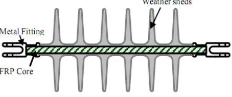
[image:1.612.200.427.458.553.2]Outdoor insulators are used in power system to support and insulate the energized conductor from the ground. Nowadays, Polymer insulators are widely used due to its better electrical performance compared to Porcelain, mica, and glass insulator [1,2]. As shown in fig.1, the basic design of the polymer insulator has a fiber reinforced plastic (FRP) core, two metal fittings and Weather sheds. FRP core is used as a load bearing structure. To protect the FRP core against various environmental stress and provide a leakage distance, weather sheds are formed outside the FRP core[3].
Fig. 1. A Clean Model of Silicone rubber insulator
As the literature review clears that the LC is converted into the flashover and finally outage of power supply, it is required to improve the available design which gives less LC. In IEC 60815-3 standard, the guidelines are given for the selection and dimensioning of the polymer insulator for the outdoor application. In this, there are certain limits are recommended for the different design parameters. In this research, the actual 11 kV insulator has been collected from the Hi-Tech Company which manufacturing the different types of polymer insulator. With the help of COMSOL Multiphysics software, the design has been modified which gives less amount of electric field and hence the LC compared to the available design. Here, the two design parameters shed angle and spacing between two sheds has been considered to modify the design to reduce the LC and so the chances of the flashover will be reduced. The idea behind selecting these two parameters is that the requirement of material remains approximately the same as that of the available design. A parametric study has been carried out to find the best combination of shed angle and the spacing between two sheds which gives least LC.
II. NUMERICALMETHOD
To find the leakage current, the electric field is required. For the analysis like potential and electric field distribution, Laplace and Poisson equation has been used. There are several methods for a solving partial differential equation such as Laplace and Poisson equation. The most widely used methods are the Finite Difference Method (FDM), Finite Element Method (FEM), Boundary Element Method (BEM) and Charge Simulation Method (CSM)[9]. In this paper, the Finite Element method is used as a numerical technique with the aid of COMSOL software. In contrast to other methods, the Finite Element Method (FEM) takes into accounts for the non-homogeneity of the solution region. Also, the systematic generality of the methods makes it a versatile tool for a wide range of problems. This method states that a complicated domain can be sub-divided into a series of smaller regions in which the differential equations are approximately solved. By assembling the set of equations for each region, the behaviour over the entire problem domain determined.
Fig.2 Subdivision of non-uniform region into small domain
Using COMSOL Multiphysics software, the Finite Element Method (FEM) analysis procedure consists of three steps [10]. These steps are Pre-processing, Solution and Post-processing. In pre-processing, one should define the geometry and material properties of the structure and the type of solver to use. The finite element model, or mesh, is created by defining the shapes of an element, the sizes of element and any variation of these throughout the model. Once the geometry is defined, the solid model is discretized into a suitable finite element mesh using a variety of meshing tools as shown in fig 2. The great care has to take while doing the meshing. Here triangular element has been selected for meshing. Usually, the mesh is created to give smaller elements in areas of stress concentration to enhance the accuracy of the solution. The boundary condition and loads are applied in this stage. Dirichlet boundary condition has been used between dielectric-conductor surfaces while Neumann has been used for the dielectric-dielectric boundary. Boundary condition defines the behaviour of the Electric field lines when it enters from one medium to another medium. The FEM provides solution of domain based closed boundary problem while outdoor Insulator is an open boundary problem as it has to work in an open environment. To make the insulator closed, a fictitious boundary is created surrounding insulator.
III.PROBLEMSOLUTIONEQUATION A. Electric Field And Potential Distribution Calculations
One simple way for electric field calculation is to calculate electric potential distribution. Then, electric field distribution is directly obtained by minus gradient of electric potential distribution. In electrostatic field problem, electric field distribution can be written as follows [11].
V
E
(1)From Maxwell’s equation
E
V
(2)ε is material dielectric constant (ε = ε0εr)
ε0 is free space dielectric constant (8.854 × 10⁻¹² F/m)
εr is relative dielectric constant of dielectric material. Placing (1) into (2), Poisson’s equation is obtained.
V
(3)Without space charge ρ=0, Poisson’s equation becomes Laplace’s equation.
0
V
(4)B. FEM Analysis of Electric Field
The finite element method is one of numerical analysis methods based on the variation approach and has been widely used in electric and magnetic field analyses since the late 1970s. Supposing that the domain under consideration does not contain any space and surface charges, two-dimensional functional F(u) in the Cartesian system of coordinates can be formed as follows:
dxdy
dy
du
dx
du
u
F
D y x
2 22
1
)
(
(5)Where εx and εy are x- and y-components of dielectric constant in the Cartesian system of coordinates and u is the electric potential.
In case of isotropic permittivity distribution (ε = εx =εy), (5) can be reformed as
dxdy
dy
du
dx
du
u
F
D
2 22
1
)
(
(6)If the effect of dielectric loss on the electric field distribution is considered, the complex functional F(u) should be taken into account as
dxdy
dy
du
dx
du
tg
j
u
F
D
2 * 2 * 0 *)
(
2
1
)
(
(7)where ω is angular frequency, ε0 is the permittivity of free space (8.85 × 10⁻¹² F/m), tgδ is tangent of the dielectric loss angle, and
u* is the complex potential.
Inside each sub-domain De, a linear variation of the electric potential is assumed as described in (8)
)
,
,
2
,
1
(
;
)
,
(
e1 e2 e3 ee
x
y
x
y
e
n
u
(8)Where, ue(x, y) is the electric potential of any arbitrary point inside each sub-domain De. αe1, αe2 and αe3 represent the computational coefficients for a triangle element e; ne is the total number of triangle elements.The calculation of the electric potential at every knot in the total network composed of many triangle elements was carried out by minimizing the functional F(u), that is,
np
i
u
u
F
ii
)
0
;
1
,
2
,
,
(
(9)Where, np stands for the total number of knots in the network. Then a compact matrix expression
C. Current Density And Leakage Current Calculation
Once the current density is find out, by taking surface integration of pollution layer, surface Leakage current can be find out with the help of following equation (11) where J is the current density and S is the surface area.
s
ds
J
I
.
(11)IV.FEMMODEL
In FEM, one has to assign some required inputs at the pre-processing stage and after the finite element calculation which is known as the processing stage, one can get the required output quantities. The process flow using FEM is shown in fig.3.
Fig.3 Input output flow of simulation activity
To draw the available geometry or the insulator, the dimensions are taken from the manufacturing company. The detail of the dimension parameters is tabulated in table 1. As to find the electric field belongs to Electrostatic solution and to find the LC belongs to Electric current solution the combination of these two modules is used for the results. Table 2 represents the properties used for the simulation.
TABLE 1:Configuration of the insulator
Dimensions Geometry
Rated voltage = 11kv
Number of shades = 3
Minimum creapage distance = 340 mm
Dry arcing Distance = 155 mm
FRP road diameter = 32 mm
Spacing (d) = 50 mm
Height system voltage = 12kv
TABLE 2: Properties of the material of the insulator
Sr. no. Material name Relative permittivity Electrical conductivity (S/m)
1 Silicon rubber 4.3 1e-12
2 FRP 7.2 1e-12
3 Forged steel 1 59e6
4 Air 1.26 1e-13
5 Pollution -conductivity 81 0.193
In the processing stage the voltage distribution, electric field distribution, current density has been found out. By taking the surface integration, the LC can be finding out. In the original design, the shed angle and the shed spacing are 150 and 50 mm respectively. As per the IEC-60815 the range of the accepted design are mentioned in table 3. The knowledge of the terminology shed angle and spacing between two sheds is shown in fig. 8. To find which combination will give the minimum LC, the parametric study has been carried out and the results of LC for various combinations is also taken.
TABLE 3:Design parameters range as per IEC-60815-3
parameter Range of parameter
Shed angle,α(degree) 5-25
Distance between shed, d (mm) 25-50
Fig.4 Shed angle ( α) and spacing (d)
V. RESULTSANDDISCUSSION
Fig.5 Comparison of voltage distribution for the available and proposed optimized design in polluted condition
Fig.6 Comparison of Electric field distribution for the available and proposed optimized design in polluted condition
(a) (b)
(a) (b)
Fig.8 Magnitude of Leakage current under polluted condition (a) Available design (b) proposed design
VI.CONCLUSIONS
Leakage current is the main reason for the flashover under the polluted condition in the outdoor insulator. It is required to optimize the insulator design to reduce the LC. In this research, the effect of the design parameters has been analyzed. By changing the two design parameters shed angle and spacing between sheds, the electric field is reduced by 15%. The LC can be reduced by 12.4% which indicates the less chances of the flashover. The research approach is cost effective as the material required is remained same. The use of new design optimizes the washing schedule which is the main concern for the utility for the insulator.
REFERENCES
[1] R. S. Gorur, A.C. Edward and T. B. Jeffrey, Outdoor Insulators, Ravi S. Gorur, Inc., Phoenix,Arizona 85044,USA,1999
[2] Looms J.S.T., Insulators for high voltages, IEEE series.
[3] Jim Goudie, “Silicone Rubber for electrical insulator” Dow Corning Corporation, USA, Rubber technology International 1998.
[4] A. Salam, Z. Nadir and M. Akabar, “Study the Effects of Different types of Contaminants on the Insulator Resistance,” Second International Conference on Electrical and Computer Engineering, ,issue 10, , pp. 240–242, Dec. 2002.
[5] R. S. Gorur and S. Venkataraman, “Prediction of Flashover Voltage of non-ceramic Insulators under contaminated conditions”, IEEE Transactions on Dielectrics and Electrical Insulation Vol. 13, No. 4;August 2006.
[6] H. M. Young, A. Haddad, A. R. Rowlands, R. T. Waters, “Effect of shape factors on the performance of polluted polymeric insulators” in High voltage engineering synopsium, Conference publication No. 467,August 1999,pp. 92-95,22-27
[7] H. M. Young, A. Haddad, A. R. Rowlands, R. T. Waters, “A simplified model to study current distribution on polluted insulators with reference to IEC 518” in international Power engineering conference, Singapore 1999. pp. 304-309
[8] R. Znaidi, Research and Assessment of Insulator Performance in Marine & Desert environment, INMR,2000
[9] Ravi S. Gorur, Robert Olsen and S. Venkataraman, “ Prediction of Flashover Voltage of Insulators Using Low Voltage Surface Resistance Measurement”, Project Report, Power Systems Engineering Research Center, Nov.2006
[10] P. Pao-la-or, “A new design of low vibration Induction motor using finite element method” Doctoral Thesis, Suranaree University of Technology, Nakhon Ratchasima, Thailand,2006
[11] S. Saangkhasaad, “High voltage Engineering” 3rd Edition,Printed in Bangkok,Thailand,March 2006
[12] A. Salam, Z. Nadir and M. Akabar, “Study the Effects of Different types of Contaminants on the Insulator Resistance,” Second International Conference on Electrical and Computer Engineering, ,issue 10, , pp. 240–242, Dec. 2002
[13] A. Cavallini, S. Chandrasekar and G. C. Montanari, “Inferring Ceramic Insulator Pollution by an Innovative Approach Resorting to PD Detection”, IEEE Transactions on Dielectrics and Electrical Insulation, Vol.14, Issue 1, pp.23-29, Feb 2007.
[14] R. Sarathi and S. Chandrasekar , “Diagnostic study of the surface condition of thee insulation structure using wavelet transform and neural networks”, Electric Power Systems Research, Elsevier, Vol.68, pp.137-147,2004.