ORIGINAL RESEARCH
INTERVENTIONAL
Compacting a Single Flow Diverter versus Overlapping Flow
Diverters for Intracranial Aneurysms: A Computational Study
X R.J. Damiano,XV.M. Tutino,XN. Paliwal,X D. Ma,XJ.M. Davies,XA.H. Siddiqui, andXH. Meng
ABSTRACT
BACKGROUND AND PURPOSE: Locally compacting the mesh of a flow diverter by a dynamic push-pull technique can accelerate intracranial aneurysm healing. We asked how this deployment strategy compares with overlapping 2 flow diverters for aneurysmal flow reduction.
MATERIALS AND METHODS:Using a high-fidelity virtual stent placement method, we simulated 3 flow-diverter strategies (single non-compacted, 2 overlapped, and single compacted) in 3 aneurysms (fusiform, large saccular, and medium saccular). Computational fluid dynamics analysis provided posttreatment hemodynamic parameters, including time-averaged inflow rate, aneurysm-averaged velocity, wall shear stress, total absolute circulation, and turnover time. We examined the relationship between the achieved degree of compaction and aneurysm orifice area.
RESULTS:Flow-diverter compaction resulted in a compaction coverage of 57%, 47%, and 22% over the orifice of the fusiform, large, and medium saccular aneurysm, respectively. Compaction coverage increased linearly with orifice area. In the fusiform aneurysm, the single compacted flow diverter accomplished more aneurysmal flow reduction than the other 2 strategies, as indicated by all 5 hemodynamic parameters. In the 2 saccular aneurysms, the overlapped flow diverters achieved the most flow reduction, followed by the single compacted and the noncompacted flow diverter.
CONCLUSIONS: Compacting a single flow diverter can outperform overlapping 2 flow diverters in aneurysmal flow reduction, provided that the compaction produces a mesh denser than 2 overlapped flow diverters and this denser mesh covers a sufficient portion of the aneurysm orifice area, for which we suggest a minimum of 50%. This strategy is most effective for aneurysms with large orifices, especially fusiform aneurysms.
ABBREVIATIONS:CC⫽compaction coverage; CFD⫽computational fluid dynamics; DPPT⫽dynamic push-pull technique; FD⫽flow diverter; HiFiVS⫽ high-fidelity virtual stent placement; IA⫽intracranial aneurysm
F
low diversion is a minimally invasive, endovascular therapy for treating intracranial aneurysms (IAs). Flow diverters (FDs) are self-expandable, densely braided metallic stents that are deployedacross the IA neck. Their low-porosity mesh redirects blood flow back into the parent vessel, decreasing flow into the aneurysm and thereby encouraging parent vessel reconstruction and an-eurysm embolization.1However, embolization does not occur immediately, leaving treated IAs at risk of rupture before com-plete occlusion is achieved.2Treatment strategies aimed at re-ducing aneurysmal flow beyond that achievable by conven-tional FD deployment can decrease the time to occlusion and reduce rupture risk.3
One of these strategies is to overlap multiple FDs to increase mesh coverage over the aneurysm neck to accelerate IA occlusion. The strategy of overlapping FDs was used in 2 large clinical trials testing the safety and efficacy of the Pipeline Embolization Device (Covidien, Irvine, California) in treating unruptured aneurysms: the Pipeline Embolization Device for the Intracranial Treatment of Aneurysms4and Pipeline for Uncoilable or Failed Aneurysms.5 Additional overlapping FDs were deployed to treat aneurysms at Received May 23, 2016; accepted after revision October 27.
From the Department of Mechanical and Aerospace Engineering (R.J.D., N.P., D.M., H.M.), Toshiba Stroke and Vascular Research Center (R.J.D., V.M.T., N.P., D.M., J.M.D., A.H.S., H.M.), Department of Biomedical Engineering (V.M.T., H.M.), and Depart-ment of Neurosurgery (J.M.D., A.H.S., H.M.), University at Buffalo, State University of New York, Buffalo, New York.
This study was supported by the National Institutes of Health (R01 NS 091075) and Covidien (VTGCC053012– 009).
Please address correspondence to Hui Meng, PhD, Department of Mechanical and Aerospace Engineering, University at Buffalo, State University of New York, Buf-falo, NY 14260; e-mail: [email protected]
Indicates open access to non-subscribers at www.ajnr.org
Indicates article with supplemental on-line appendix.
Indicates article with supplemental on-line photo.
the discretion of the neurointerventionalists, and an analysis of treatments at the conclusions of the trials showed that the average number of FDs used per case was 1.52 and 3.1, respectively. These trials demonstrated 6-month occlusion rates of 93% and 73.6%, respectively, supporting the efficacy of using overlapping FDs to treat IAs. Computational studies of sequentially overlapping stents for treating IAs have supported this concept, showing in-creased flow reduction with the increases in mesh coverage over the IA orifice.6More recently, we simulated realistic deployment of the Pipeline Embolization Device and demonstrated that over-lapping 2 devices reduced aneurysmal flow velocity 30% more than deploying 1 device.7
However, negative clinical consequences of overlapping FDs have also been reported, including in-stent thrombosis, stenosis, and perforator occlusion.8,9These complications are likely due to the increased metal surface area and lowered porosity due to ad-ditional FDs.8It would be desirable to deploy a single FD but to achieve as much aneurysmal flow reduction as overlapping mul-tiple FDs, to reduce the risk of these complications.
Most interesting, because its individual wires can slide over one another, an FD can generate spatially varying mesh density when deployed. This ability was demonstrated by several bench-top experiments that showed that when longitudinally com-pressed during deployment, an FD expands radially and its wires compact into a localized zone of higher mesh density.10,11To use this property, we recently developed a novel deployment strategy to achieve local FD compaction for patient-specific IAs: the dy-namic push-pull technique (DPPT).12 With this strategy, the mesh density of an FD can be increased over the IA orifice during deployment through synergistic push-and-pull maneuvers be-tween the microcatheter and delivery wire. We demonstrated the use of the DPPT for patient-specific IAs in vitro by physically deploying FDs and compacting their meshes in several IA flow phantoms.13We also showed that an FD compacted by using the DPPT reduced aneurysmal flow velocity 38% more than a non-compacted, uniformly deployed FD.14A recent in vivo study of canine aneurysm models also found that compacted FDs resulted in more frequent occlusion than noncompacted FDs.15We hy-pothesized that a single compacted FD could realize the benefits of overlapping multiple FDs without associated complications.
This study tested numerically whether compacting a single FD could be as effective as 2 overlapped FDs in aneurysmal flow re-duction. To this end, we used a finite element method– based modeling technique—the high-fidelity virtual stenting (HiFiVS)12 method—to simulate various FD deployment strategies, includ-ing sinclud-ingle noncompacted, 2 overlapped, and sinclud-ingle compacted. Applying these modeling strategies, we virtually “treated” 3 rep-resentative patient-specific IAs: a fusiform, a large saccular, and a medium saccular aneurysm. We then performed computational fluid dynamics (CFD) analysis to assess hemodynamic tions in each scenario and compared the resulting flow modifica-tions by using 5 hemodynamic parameters.
MATERIALS AND METHODS
Creation of IA Models
For this computational study, we chose 3 representative patient-specific IAs as test cases: a medium 9-mm fusiform basilar trunk
IA, a large 18-mm saccular internal carotid artery IA, and a me-dium 9.5-mm saccular internal carotid artery IA. They were all treated by FDs at Gates Vascular Institute (Buffalo, New York), and their pretreatment angiographic images were obtained at the time of treatment under institutional review board approval. Al-though all 3 cases were treated by FDs, the FD strategies tested in the current numeric study answered the question of the effective-ness of different competing treatment strategies and did not cor-respond to the actual treatments received by these patients.
To create the 3D IA models, we segmented their angiographic images by using the level set and marching cube methods in The Vascular Modeling Toolkit (www.vmtk.org).16To make the FD deployment simulations computationally tractable, we assumed that the IA models were rigid. This assumption was reasonable because FDs exhibit lower radial forces1than closed-pore stents and thus have less effect on vessel morphology.
FD Size Selection
We selected the FD size for each IA by following standard clinical procedures.17The nominal diameter of an FD was chosen to ap-proximate the size of the recipient parent vessel in each IA, and the nominal length was chosen to be at least 6 mm longer than the length of the IA neck. This process gave rise to 3 FD specifications for each IA: FDs measuring at least 5⫻13, 4.25⫻12, and 3.25⫻ 10 mm in the fusiform, large, and medium IAs, respectively.
Modeling the Deployment Strategies of Noncompacting and Overlapping FDs with HiFiVS
The HiFiVS12method was used to virtually deploy FDs in this study. As previously described, HiFiVS is a finite element meth-od– based FD simulation technique that models several compo-nents of the FD delivery system, including the crimper, micro-catheter, distal coil, and proximal pusher. All deployment mechanics and critical steps that affect the final configurations of FDs were simulated, including crimping, delivery, release, and expansion.
The HiFiVS method was rigorously validated in our previous experimental studies.12,13Side-by-side comparisons between ex-perimental deployment of FDs in transparent IA phantoms and in silico deployment in identical IA models showed excellent agree-ment, as demonstrated inFig 6of Ma et al (2013).12Local mesh characteristics of compacted FDs deployed by HiFiVS matched those deployed experimentally by the DPPT, as demonstrated in
Fig 2of Ma et al (2014).13
In the current study, we modeled the FDs after the Pipeline Embolization Device. The wire braiding pattern for each FD was generated in Matlab (MathWorks, Natick, Massachusetts) on the basis of mathematic description.18The FD deployment procedure was simulated by using the finite element solver Abaqus/Explicit 6.13 (SIMULIA; 3DS, Waltham, Massachusetts).
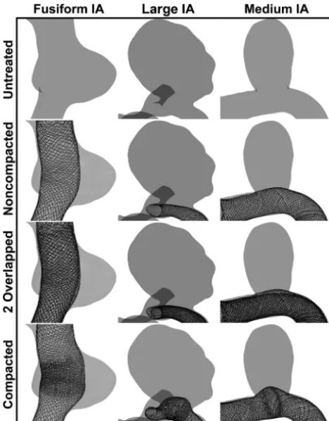
mea-suring 5⫻20, 4.5⫻14, and 3.25⫻12 mm was coaxially deployed in the fusiform, large, and medium IAs, respectively.
Modeling the Deployment Strategy of Compacting a Single FD with HiFiVS
The previously described modeling technique of emulating the DPPT12,13was used in the current study to compact a single FD. This consisted of retracting the microcatheter proximally as in regular noncompacting deployment to unsheathe the FD, while advancing the proximal pusher distally to generate dense FD mesh over the IA orifice.
To generate the most flow diversion in each IA, we maximized the FD compaction during deployment by maneuvering the movement of the microcatheter and proximal pusher. The simu-lation procedure was stopped if the FD started to migrate distally or the wires of the FD began to unwind or tangle. Using this procedure, we maximally compacted FDs measuring 5⫻ 20, 4.5⫻20, and 3.25⫻14 mm in the fusiform, large, and medium IAs, respectively.
Quantification of FD Mesh Characteristics
The amount of aneurysmal flow reduction achievable by an FD in a patient-specific IA is affected by its mesh porosity and pore density in its fully deployed state.1An ideal FD has low porosity and high pore density to maximize flow diversion1: Porosity rep-resents the amount of empty space created by the mesh pores of the FD, and pore density, the number of pores per unit area.19We quantified these parameters near the IA orifice along the length of a deployed FD in 5 consecutive zones: proximal vessel, proximal transition, middle, distal transition, and distal vessel, as defined previously on the basis of an FD compacted via the DPPT.13The proximal/distal vessel zones were the portions of the FD con-strained in the parent vessel. The FD mesh in the middle zone (ie, over the IA orifice) was compacted because the goal of the DPPT is to increase mesh density over the IA orifice.13The remainder of the IA orifice not covered by the middle zone was covered by the proximal/distal transition zones. Even though FDs deployed without compaction presented more or less uniform meshes, to compare porosity and pore density between different strategies, we analyzed all FDs in these 5 zones.
Quantification of FD Mesh Compaction
When an FD is axially compressed, 2 things happen simultane-ously: The woven wires of the FD compact together and the FD construct expands radially. With FD deployment via the DPPT, the aim is to create local mesh compaction over the IA orifice to block flow into the IA.13While the FD wires compact together, the IA orifice provides space to allow the FD construct to expand during compaction. Clearly the size of the orifice limits the degree to which an FD can be compacted and thus the effectiveness of the FD compaction strategy at improving aneurysmal flow reduction. Therefore, we investigated the relationship between the IA orifice area and the achievable compaction. This information could help clinicians determine the types of IA geometry for which the FD compaction strategy is most effective.
To that end, we measured IA orifices on the plane that sepa-rates the IA sac from the parent vessel for the saccular IAs and on
the plane that separates the largest bulge from the parent vessel for the fusiform IA. Once the orifice was identified, we quantified the degree of achievable FD compaction by a new parameter, the compaction coverage (CC), as defined in Equation 1. Here, com-paction coverage represents the percentage of the IA orifice cov-ered by the middle zone of the compacted FD.
1) CC共%兲⫽Compaction Zone Area IA Orifice Area
CFD Simulations
Pre- and posttreatment hemodynamics in all IA models were sim-ulated by using CFD in Star-CCM⫹v.10 (CD-adapco, Melville, New York). Blood flow was assumed to be pulsatile, laminar, in-compressible, and Newtonian (density⫽1056 kg/m3, dynamic viscosity⫽3.5 cP). A patient-specific, pulsatile velocity waveform was prescribed at each inlet, having a mean velocity matching typical flow rates at each IA location. A traction-free boundary condition was specified at each outlet.7To solve for the aneurys-mal flow fields, we spatially discretized each IA into unstructured grids by using polyhedral cells.7Additional details of the CFD meshing parameters and the results of a mesh independence study are included in the On-line Appendix. Three cardiac cycles were simulated to ensure numeric stability of the flow solutions in all IA models. All hemodynamic parameters presented were time averages over the third cycle.
To compare aneurysmal flow modifications by the 3 FD strat-egies, we assessed posttreatment changes of 5 hemodynamic pa-rameters: inflow rate, aneurysm-averaged velocity, wall shear stress, total absolute circulation, and turnover time. Previous studies reported that FDs reduced inflow rate, velocity, and wall shear stress and increased turnover time and that the amount of change correlated with IA occlusion rates.20,21In addition, we also examined posttreatment changes in the total absolute hydrody-namic circulation. This new parameter is a modified version of hydrodynamic circulation that was used previously to compare aneurysmal flow changes by several custom-designed FDs.19By definition, hydrodynamic circulation is an integration of vorticity flux over a region. Because the positive and negative vortex sub-regions could cancel out and give zero or small total circulation in this region, the use of hydrodynamic circulation could mask the true amount of rotational flow activity in this region. To capture the total amount of rotational flow activity of both positive and negative vortices in an aneurysm, we defined the total absolute circulation (⌫A) as the integration of the absolute value of vortic-ity flux over the IA midplane as shown in Equation 2:
2) ⌫A⫽
冕冕
兩៝ 䡠nˆ兩dAdefine the IA sac as the volume enclosed by the wall of the IA and the IA orifice.
RESULTS
Compacting a Single FD Achieved Similar Porosity and Pore Density as Overlapping FDs
Figure 1shows the geometry of the 3 IA models and the FDs virtually deployed by the 3 FD treatment strategies in each IA. The fusiform IA (on the basilar artery) involves the entire circumfer-ence of the parent vessel, with the largest bulge protruding to the right (left column ofFig 1). The 2 saccular IAs both occur sidewall on the internal carotid artery. After treatment, the mesh density appears rather uniform in all 3 IA models for the noncompacted FD and overlapped FDs. The compacted FD, on the other hand, shows highly variable mesh density in all 3 cases, bulging into the IA sac and compacting in a distinct zone of higher mesh density. The middle zone is largest in the fusiform IA and decreases in the large and medium IAs. The remaining zones of the compacted FD are less dense in comparison with the middle zone in all 3 IAs.
Figure 2shows the quantification of mesh variations in terms of porosity and pore density of all virtually deployed FDs. The 5 mesh zones for calculating these quantities are illustrated inFig 2A, with the fusiform IA as an example, wherein the middle zone (M) of the compacted FD has much higher mesh density over other zones.Figure 2B,-Cshows porosity and pore density, re-spectively, plotted over the consecutive mesh zones for all FD strategies. Overall, the single noncompacted FDs have the highest porosity and lowest pore density, while the overlapped FDs have the lowest porosity and highest pore density. The compacted FDs show large variations in both porosity and pore density along
their lengths. They are generally similar to those in the single noncompacted FDs, but in the middle zone, they have a large jump, approaching or exceeding the overlapped FDs, except for 2 cases.
Compaction Coverage Increased Linearly with IA Orifice Area
To explore the relationship between the maximally achievable FD compaction and IA geometry, we quantified the IA orifice area, the area of compaction, and the compaction coverage.Figure 3
shows the FD mesh at the orifices of the 3 IAs and the CC plotted against the orifice area. The fusiform IA orifice had the largest coverage by the middle zone (ie, the compacted portion), and the medium IA orifice had the smallest (Fig 3A). Conversely, the me-dium IA orifice had the largest coverage by the transition zones (ie, the noncompacted portions), and the fusiform IA orifice had the smallest. The orifice areas for the fusiform, large, and medium IAs were 34.5, 30.0, and 14.7 mm2, respectively, while the corre-sponding CCs were 57%, 47%, and 22%, respectively.Figure 3B demonstrates a strong linear correlation between the CC and IA orifice area (R2⫽0.9965). In both saccular IAs, CC was below 50%, meaning less than half of the IA orifice was covered by the middle zone.
Compacting a Single FD Outperformed Overlapping 2 FDs in Aneurysmal Flow Reduction in the Fusiform IA
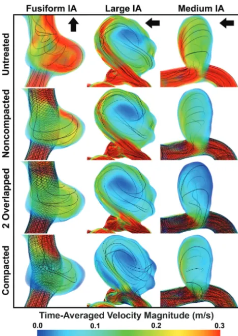
We performed CFD simulations for all 12 IA models shown inFig 1, including the 3 untreated IAs, and posttreatment hemodynam-ics by using all 3 treatment strategies in each IA.Figure 4shows the volume-rendered time-averaged velocity magnitude in all 12 IA models. In addition to the velocity magnitude (rendered in color), streamlines (rendered in black) are plotted to visualize the flow modifications by each FD strategy. In the fusiform IA, a strong vortex was formed in the large bulge, and it was diminished by the FDs to various extents, with the compacted FD delivering the most reduction. In the large and medium saccular IAs, an inflow jet entered the IA sac distally and circulated throughout the IA sac before exiting proximally. In the large IA, the size and velocity of the inflow jet was reduced most by the compacted FD, followed by the overlapped FDs and then the noncompacted FD. On the other hand, in the medium IA, the overlapped FDs reduced the size and velocity of the inflow jet the most. The compacted FD appeared to disrupt the inflow jet as much as, but no more than, the noncom-pacted FD in the medium IA.
To quantify the different effects of flow reduction by the 3 FD strategies, we calculated posttreatment modifications in the time-averaged inflow rate, aneurysm-time-averaged velocity, wall shear stress, total absolute circulation, and turnover time, all shown in
Fig 5. Regardless of the deployment strategy, FDs reduced intra-aneurysmal flow in all 3 IAs, as evidenced by the decrease in inflow rate, aneurysm-averaged velocity, wall shear stress, and total ab-solute circulation and an increase in turnover time from the un-treated IAs. In the fusiform IA, the compacted FD outperformed the overlapped FDs in all 5 hemodynamic parameters. In contrast, the overlapped FDs outperformed the compacted FD in the large and medium IAs, except for total absolute circulation in the large IA, where the compacted FD performed best.
[image:4.594.52.286.46.345.2]DISCUSSION
In this computational study, we tested whether a single compacted FD could outperform 2 overlapped FDs in IA flow reduction. Our results suggest that this goal is achievable provided that the compaction of the single FD can achieve 2 conditions: 1) It produces a com-pacted mesh in the middle zone that is denser than 2 overlapped FDs, as judged by both porosity and pore density; and 2) this denser mesh covers a sufficient portion of the IA orifice area, of which we suggest a minimum of 50%.
In the fusiform IA model, compact-ing a scompact-ingle FD achieved both of these conditions. Not surprising, the com-pacted FD outperformed the 2 over-lapped FDs in all 5 hemodynamic pa-rameters. In the 2 saccular IAs, however, compacting a single FD did not achieve both compaction conditions above. In the large saccular IA, the porosity did not get down to the level of the 2 over-lapped FDs (Fig 2B), while in the me-dium saccular IA, the pore density did not reach that of the overlapped FDs (Fig 2C) and neither IA allowed CC of ⬎50%. We believe that this inadequate compaction was responsible for the flow simulation results in the 2 saccular IAs—that is, the compacted FD did not outperform the overlapped FDs in aneu-rysmal flow reduction. We further found that the degree to which an FD can be compacted and thus the ability to achieve both mesh conditions when compacting an FD are linearly related to the area of the aneurysm orifice. An FD can be compacted to a larger degree over an IA with a larger orifice because a large orifice provides more space for the FD to expand. This radial expansion occurs to accommodate the compaction of the woven wires of the FD as the FD is axially compressed. Therefore, the salient find-ing of this study is that compactfind-ing a sin-gle FD can outperform overlapping 2 FDs in aneurysms with large orifices, es-pecially fusiform IAs.
We believe that compacting a single FD could be a superior strategy to over-lapping multiple FDs, from both a bio-logic and economic standpoint. One concern with overlapping multiple FDs is that it increases the mesh density in the parent vessel, thereby increasing the FIG 2. Porosity and pore density distributions of deployed FDs resulting from all 3 deployment
methods in the 3 IAs.A, Deployed FD meshes in the fusiform IA and demarcations of FD zones used for porosity and pore density calculations: proximal vessel (PV), proximal transition (PT), middle (M), distal transition (DT), and distal vessel (DV). These zones are defined on the basis of the compacted FD but applied to all 3 deployment strategies for calculation of porosity and pore density.B, Porosity distribution.C, Pore density distribution. Thearrowsindicate middle zones in which the compacted FD has lower porosity or higher pore density than the overlapped FDs, whereas theovalsindicate middle zones in which it does not.
[image:5.594.56.375.47.359.2] [image:5.594.65.360.445.667.2]chance of perforator occlusion.8Overlapping multiple metal de-vices also increases the risk for in-stent thrombosis and stenosis.9 In contrast, the strategy of compacting a single FD increases the mesh density only over the IA orifice, but not in the parent vessel, thereby minimizing the risk of occluding nearby perforators. In addition, this strategy uses a single device, thereby minimizing the amount of thrombogenic metal and eliminating the costs and procedural risks associated with additional devices.
The goal of compacting an FD is to increase mesh density over the IA orifice beyond that achievable by not compacting an FD, in the hope of accelerating IA occlusion. However, failing to achieve adequate mesh compaction may render the compacted FD no more effective at aneurysmal flow reduction than a noncom-pacted FD. This result is because the less area of an FD that is compacted over the IA orifice, the more area of the orifice that is left at a lower mesh density. In other words, the smaller the middle zone, the larger is the transition zones. Benchtop experiments have shown that mesh transition zones are unavoidable when compacting an FD.10In addition, the experiments showed that the transition zones were always less dense than the middle zone; this feature could compromise the ability of the FD mesh to divert aneurysm inflow. Our study supports this observation. We found that the mesh transition zones of the compacted FDs were ap-proximately as dense as those of the noncompacted FDs in all 3 IAs (Fig 2B,-C). The implications of this result in our study were FIG 4.Time-averaged, volume-rendered velocity magnitude in all 3 IAs for each FD strategy. Streamlines are plotted to enhance visual-ization of flow modifications due to each FD strategy. Thearrows
indicate the flow direction for each untreated IA.
[image:6.594.52.286.44.374.2] [image:6.594.312.520.50.640.2]most revealing when considering the medium IA, which has the smallest orifice area of the 3 IA cases. In this aneurysm, the compacted FD disrupted the IA inflow jet as much as but no more than the noncompacted FD, and the jet passed through the distal transition zone of the FD (Fig 4). We could not further compact the FD due to the small orifice (⬍50% CC). Consequently, most of the orifice was covered by the lower mesh density transition zones. Thus, inadequate compaction of an FD leaves the orifice covered by lower density mesh, thereby delaying or preventing thrombosis due to insufficient flow diversion. On the basis of our results, we suggest ensuring that at least 50% of the IA orifice is covered by the higher density middle zone when compacting an FD.
On the other hand, excessive compaction of an FD could also cause complications, for example, causing the FD to pro-lapse into the aneurysm or migrate along the parent vessel. Gentric et al,15in an attempt to treat several canine aneurysm models by compacting single FDs in vivo, experienced exces-sive compaction, which caused 4 FDs to prolapse into the an-eurysm sac during deployment and 1 to migrate distally along the parent vessel following deployment. In the current in silico study, we also saw that if too much force was applied to the proximal pusher during compaction, the FD would migrate along the parent vessel. Consequently, we had to rerun the simulation with less force applied to ensure that the FD was anchored properly in the parent vessel. In the clinical setting, however, it would be extremely hard to salvage a prolapsed or migrated FD after deployment. Therefore, extra precaution is required to avoid excessively compacting an FD and causing FD prolapse or migration during the intervention.
Our study shows that no FD deployment strategy, including compacting FDs, is optimal for all IAs. We believe that IA geom-etry is the most important determining factor for the success of any flow-diversion strategy. Other factors also come into play as well. For example, the type and dimensions of the FD devices will determine the deployment process and the resulting mesh char-acteristics (eg, porosity and pore density). These, in turn, will determine the flow-diversion effect of the FD strategy (as demon-strated by Mut et al22). Furthermore, the success of the FD treat-ment also depends on the experience level of the neurointerven-tionalist. A steep learning curve is well-recognized in performing FD deployments, and the deployment procedure requires sub-stantial technical ability,23 especially for complex deployment techniques such as compacting or overlapping FDs.
CONCLUSIONS
We investigated whether compacting a single FD could outper-form overlapping 2 FDs in aneurysmal flow reduction in 3 patient-specific IAs. We found that compacting a single FD can be as effective as overlapping 2 FDs in aneurysmal flow reduc-tion, provided that the compaction of the single FD can pro-duce a dense mesh in the middle zone that is denser than 2 overlapped FDs and this denser mesh covers a sufficient por-tion of the IA orifice area, of which we suggest a minimum of 50%. FD compaction is most suitable for IAs with large orifice areas, especially fusiform IAs.
ACKNOWLEDGMENTS
The authors thank the Center for Computational Research at the University at Buffalo for providing computational resources.
Disclosures: Adnan H. Siddiqui—UNRELATED:Board Membership: Intersocietal Ac-creditation Committee;Consultancy: Codman & Shurtleff, Medtronic, GuidePoint Global Consulting, Penumbra, Stryker, MicroVention, W.L. Gore & Associates, Three Rivers Medical Center, Corindus Vascular Robotics, Amnis Therapeutics, CereVasc, Pulsar Vascular, The Stroke Project, Cerebrotech Medical Systems, Rapid Medical, Lazarus (acquired by Medtronic), Medina Medical (acquired by Medtronic), Reverse Medical (acquired by Medtronic), Covidien (acquired by Medtronic), Neuroavi, Silk Road Medical, Rebound Medical;Consulting Fee or Honorarium: Medtronic, Mi-croVention;Stock/Stock Options: StimSox, Valor Medical, Neuro Technology Inves-tors, Cardinal Health, Medina Medical, Buffalo Technology Partners, International Medical Distribution Partners;Other: Principal Investigators/National Steering Com-mittees for various trials, Comments: the Penumbra 3D Separator Trial, the Covidien (Now Medtronic) Solitaire With the Intention For Thrombectomy as PRIMary Endo-vascular Treatment Trial and SWIFT DIRECT Trials, the MicroVention FRED Trial and CONFIDENCE Study, the LARGE Trial, POSITIVE Trial, Penumbra COMPASS Trial, and Penumbra INVEST Trial. Hui Meng—RELATED:Grant: National Institutes of Health*; UNRELATED:Consultancy: National Institutes of Health study sections*;Grants/ Grants Pending: Brain Aneurysm Foundation*;Payment for Lectures Including Ser-vice on Speakers Bureaus: University of California, San Francisco*;Patents (Planned, Pending, or Issued): University at Buffalo.* *Money paid to the institution.
REFERENCES
1. Sadasivan C, Cesar L, Seong J, et al.An original flow diversion device
for the treatment of intracranial aneurysms: evaluation in the rabbit elastase-induced model. Stroke 2009;40:952–58 CrossRef Medline
2. Kulcsa´r Z, Houdart E, Bonafe´ A, et al.Intra-aneurysmal thrombosis
as a possible cause of delayed aneurysm rupture after flow-diver-sion treatment.AJNR Am J Neuroradiol2011;32:20 –25CrossRef Medline
3. Szikora I, Berentei Z, Kulcsar Z, et al.Treatment of intracranial
an-eurysms by functional reconstruction of the parent artery: the Bu-dapest experience with the Pipeline Embolization Device.AJNR Am J Neuroradiol2010;31:1139 – 47CrossRef Medline
4. Nelson PK, Lylyk P, Szikora I, et al.The Pipeline embolization device
for the intracranial treatment of aneurysms trial.AJNR Am J Neu-roradiol2011;32:34 – 40CrossRef Medline
5. Becske T, Kallmes DF, Saatci I, et al.Pipeline for uncoilable or failed aneurysms: results from a multicenter clinical trial.Radiology2013;
267:858 – 68CrossRef Medline
6. Kim M, Levy EI, Meng H, et al.Quantification of hemodynamic
changes induced by virtual placement of multiple stents across a wide-necked basilar trunk aneurysm.Neurosurgery2007;61:1305–
12; discussion 1312–13CrossRef Medline
7. Damiano RJ, Ma D, Xiang J, et al.Finite element modeling of
endo-vascular coiling and flow diversion enables hemodynamic predic-tion of complex treatment strategies for intracranial aneurysm. J Biomech2015;48:3332– 40CrossRef Medline
8. Tan LA, Keigher KM, Munich SA, et al.Thromboembolic
complica-tions with Pipeline Embolization Device placement: impact of pro-cedure time, number of stents and pre-propro-cedure P2Y12 reaction unit (PRU) value. J Neurointerv Surg 2015;7:217–21 CrossRef Medline
9. Tse MM, Yan B, Dowling RJ, et al.Current status of Pipeline
embo-lization device in the treatment of intracranial aneurysms: a review. World Neurosurg2013;80:829 –35CrossRef Medline
10. Makoyeva A, Bing F, Darsaut TE, et al.The varying porosity of
braided self-expanding stents and flow diverters: an experimental study.AJNR Am J Neuroradiol2013;34:596 – 602CrossRef Medline
11. Shapiro M, Raz E, Becske T, et al.Variable porosity of the Pipeline
embolization device in straight and curved vessels: a guide for op-timal deployment strategy.AJNR Am J Neuroradiol2014;35:727–33
CrossRef Medline
stent-ing (HiFiVS) for intracranial aneurysm flow diversion: in vitro and in silico.Ann Biomed Eng2013;41:2143–56CrossRef Medline
13. Ma D, Xiang J, Choi H, et al.Enhanced aneurysmal flow diversion using
a dynamic push-pull technique: an experimental and modeling study. AJNR Am J Neuroradiol2014;35:1779 – 85CrossRef Medline
14. Xiang J, Ma D, Snyder KV, et al.Increasing flow diversion for
cere-bral aneurysm treatment using a single flow diverter.Neurosurgery
2014;75:286 –94; discussion 294CrossRef Medline
15. Gentric JC, Salazkin I, Gevry G, et al.Compaction of flow diverters
improves occlusion of experimental wide-necked aneurysms. J Neurointerv Surg2016;8:1072–77CrossRef Medline
16. Antiga L, Piccinelli M, Botti L, et al.An image-based modeling
framework for patient-specific computational hemodynamics. Med Biol Eng Comput2008;46:1097–112CrossRef Medline
17. Eller JL, Dumont TM, Sorkin GC, et al.The Pipeline embolization
device for treatment of intracranial aneurysms.Expert Rev Med De-vices2014;11:137–50CrossRef Medline
18. Ma D, Dargush GF, Natarajan SK, et al.Computer modeling of
de-ployment and mechanical expansion of neurovascular flow
di-verter in patient-specific intracranial aneurysms.J Biomech2012;
45:2256 – 63CrossRef Medline
19. Lieber BB, Sadasivan C.Endoluminal scaffolds for vascular
recon-struction and exclusion of aneurysms from the cerebral circulation. Stroke2010;41:S21–25CrossRef Medline
20. Xiang J, Damiano RJ, Lin N, et al.High-fidelity virtual stenting:
modeling of flow diverter deployment for hemodynamic character-ization of complex intracranial aneurysms.J Neurosurg2015;123:
832– 40CrossRef Medline
21. Mut F, Raschi M, Scrivano E, et al.Association between
hemody-namic conditions and occlusion times after flow diversion in cere-bral aneurysms.J Neurointerv Surg2015;7:286 –90CrossRef Medline
22. Mut F, Cebral JR.Effects of flow-diverting device oversizing on
he-modynamics alteration in cerebral aneurysms.AJNR Am J Neuro-radiol2012;33:2010 –16CrossRef Medline
23. Jabbour P, Chalouhi N, Tjoumakaris S, et al.The Pipeline