Optimal Process Control Parameters Estimation
in Aluminium Extrusion for Given Product
Characteristics
P. Kathirgamanathan and T. Neitzert
∗Abstract—This paper investigates a technique to find an optimal set of conditions for an isothermal process to extrude a product for a given shape and material properties with minimal defects. The inputs to this model are: the product geometry and its mate-rial data such as flow curve and microstructure during dynamic recrystallization. This is an inverse problem and the model is formulated as a non-linear least-squares minimization problem coupled with a finite element model for the extrusion process. It is done by constructing an iterative procedure using an op-timisation routine such as
M
ATLAB’s lsqnonlin and at each iteration, the extrusion flow is solved usingABAQUS. First all control points of a Bezier-curve for
the die surface that minimizes the redundant strain inside the deformation zone are found. Then the ini-tial billet temperature, die temperature and the ram speed that closely match with the strain rates and temperatures for the desired microstructure (grain size) are obtained.
Keywords: Extrusion; Inverse problem; Parameter es-timation; Optimization.
1
Introduction
The metal flow during extrusion through a die is complex and not uniform, which causes a cross-cracking, bending, distorting and twisting of the extruded product. To im-prove the quality of the workpiece, the die cross-section layout and operating conditions must be taken into ac-count in the design of a new product.
Computer simulation of extrusion using the finite element method is a popular option to replace the traditional trial and error method during process design. A finite ele-ment model, which is capable of describing the behavior of metal flow during extrusion, requires several input data such as die geometry, material behavior laws, friction laws and operating conditions.
In reality, material data can be obtained using available experimental data, but optimal values of die geometry
∗Manuscript received March 01, 2008. This work was supported
by Technology New Zealand. Authors are with School of Engineer-ing, Auckland University of Technology, Auckland, New Zealand; email: [email protected], [email protected]
and operating conditions are often not accurately known and therefore guessed. Methods to determine die geom-etry and operation conditions are an important part of designing an extrusion process.
Several articles have been published in this area. Wifi et al[6], used the incremental slab technique and Bezier-curve technique to find the optimum Bezier-curved die profile that minimizes the extrusion load for a hot extrusion process. Leeet al[1] used the finite element method and flexible polyhedron search method to produce a uniform microstructure. They used Bezier-curves to generate all possible die profiles and used plain carbon steel for the billet.
The novel concept of this research is to determine the optimal conditions of isothermal extrusion with regards to billet temperature, container temperature, extrusion speed and microstructure for a non-adiabatic die profile basing it on techniques available in the literature.
2
Forward Problem
Extrusion is a thermo-mechanical deformation process in which a block of metal (billet) is forced through the die opening of a smaller cross sectional area than that of the original billet. In this process, the large deformations are mainly plastic or viscoplastic, allowing the elastic part to be neglected. Strain is a measure of deformation and at high strain rates metal flow is analogous to fluid flow. Therefore the material behavior can be described as that of fluid flow.
(i) Conservation of mass Dρ
Dt +ρ∇ ·V= 0 (1) where ρis the density of the material and V is the velocity vector. If the material is incompressible, density is unchanged and the Equation (1) is simpli-fied to
∇ ·V= 0 (2) (ii) Conservation of momentum
ρDV
where f is the body force per unit mass, and σ is Cauchy stress tensor. For viscous incompressible fluid
σ=−PI+s (4) whereP is the pressure,Iis the unit tensor and
sij =Cεij˙ . (5)
whereC is defined by
C= 2K√3˙¯εm−
1
(6)
here K represents the consistency of the material, mis the strain rate sensitive index and the effective strain rate
˙¯ ε=
r
2
3εij˙ εij˙ . (7)
˙
εis the strain rate tensor and it is defined by
˙ ε= 1
2
(∇V) + (∇V)T
(8)
(iii) Conservation of energy
ρc
∂T
∂t +V· ∇T
=−∇ ·(−k· ∇T) + ˙Q (9)
wherec is the specific heat,k=kI, kdenotes ther-mal conductivity,Tis the temperature and ˙Qis the rate of heat generated per unit volume.
The exact mathematical analysis of the extrusion process is very complex and has not been fully resolved. But finite element techniques deliver approximate numerical solutions to it. We implemented this with the ABAQUS finite element program.
3
Inverse Problem
The goal here is to determine the input data (param-eters) of the forward problem which leads to a given result. In this problem, the die design parameters and process parameters are not known, but the shape and properties of the final product are known. We assume here that the desired grain size of the material is known, but the exact die geometry, initial billet temperature and ram speed are unknown. Our aim is to estimate the exact die geometry and the process parameters. This problem is known mathematically as an inverse problem and can be seen as an optimization problem whereby the objective function to minimize is the gap between the expected result and finite element simulation results.
First of all, a mathematical definition of the gap between the expected and simulation results is required as an objective function. The aim of optimization is to find the best set of parameters that minimizes an
objective function by improving the performance in the direction of optimas. The aim of the approach is to find the global minimum on a given search space by maximizing or minimizing the objective function subjected to the given constraints. In the case of a minimization problem, the mathematical formulation of the problem can be stated as follows
Minimize f(p)
subject to gj(p)≥0 j= 1, . . . , n1
hk(p) = 0 k= 1, . . . , n2 (10)
where f(p) is the objective function, gj(p), hk(p) are constraints function andpis a vector of design variables and process variables.
3.1
Design variables
In order to determine the optimal die profile, it is essen-tial to describe an arbitrary die profile by a mathematical expression and obtain the design variables from the ex-pression. The design variables will then be optimized to get a desired result. In this study Bezier curves with five control points are used to obtain the arbitrary die profile. The Bezier curve which has the control points (xi, yi), i= 1, . . . ,5 is given by [2]
x(t) = N
X
i=0
xi+1Bi,N(t), and
y(t) = N
X
i=0
yi+1Bi,N(t), (11)
whereN = 4,t∈[0,1],and
Bi,N(t) = N! i!(N−1)!t
i(1
−t)N−i
Using these control points an infinite number of die sur-faces can be created.
3.2
Process variables
Theoretically, the process variables which can influence the extrusion process are the ram speed V, initial tem-perature of the billetT0 and the friction conditionsmat
the billet/tool interface.
3.3
Important factors in the product
opti-mization
3.3.1 Die life
strength of a die can be affected by wear and this wear is closely related to the load on the surface of a die cav-ity. By distributing the load on the die surface wear can be distributed along the surface and it leads to increases in die life. Therefore the optimization constraint for in-creases in die life have to be in the form (σV AR=)
min
Y
X
i
(σi+1−σi)2+ (τi+1−τi)2
1 2
+λp (12)
where σi is the axial stress in the i−th node, τi is the friction stress in the i−th node,pis the extrusion load, λis a penalty parameter andY, is a vector of design and process parameters.
3.3.2 Isothermal extrusion
Isothermal extrusion is a process of maintaining a con-stant temperature during the extrusion process inside the deformation zone. Achieving this condition is very im-portant for the production of uniform, high-quality prod-ucts. Isothermal conditions can be achieved mechanically by adjusting the speed of the ram, initial temperature of billets and die and by carefully designing the die for each product. Based on these considerations the optimization constraint to achieve isothermal extrusion can be written as follows.
min
Y
Z tf
0
(T(x, y, t)−Td)dt, (13) whereT(x, y, t) is the temperature inside the deformation zone as a function of space and time, Td is the average temperature or desired temperature inside the deforma-tion zone and tf is a time to complete the particular extrusion process.
3.3.3 Flow balance
An evenness of exit flow is an important part in the die design to avoid part distortion and to be able to yield an extruded part within the specified tolerances. The uniform die exit velocity can be obtained by adjusting the die land length. The optimization constraint to increase the evenness of exit flow is therefore
min
Y
" N
X
1
(Vi−V¯)2 #
, (14)
whereVi is the nodal velocity of thei−th node,N is the number of nodes along the die exit and ¯V is the average nodal velocity along the die exit.
3.3.4 Distortion
The success of an extrusion process depends mainly on reducing the distortion and minimizing the redundant
strain in the extruded product as well as controlling the strain rate inside the deformation zone. Literature in the field of metal forming processes suggests that redundant strain and distortion are related to each other. Based on the theory and available literature the following three criteria can be used to minimize distortion.
(i) Distortion variation:
min
Y
"N
X
1
(Ui−U¯)2
)
#
(15)
whereUi is the displacement of the nodeiand ¯U is the average displacements of transverse nodes at the die exit.
(ii) Average effective strain:
min
Y
"N
X
1
(εi−εIdeal¯ )2
)
#
(16)
where ¯εIdealis the ideal effective strain and is defined by
¯
εIdeal= 2 lnR0
Rf (17)
for the axisymmetric extrusion.
(iii) Strain rate deviation:
min
Y
"N
X
1
( ˙εi−¯˙ε)2
)
#
(18)
3.4
Objective and constraint function
The selection of the objective function is associated with the user’s specific needs. Here our aim of the study is to extrude a product with given characteristics. Therefore the objective function must involve the microstructure (grain size) of the final product. But the optimal strain rate, strain and temperature trajectories can be obtained to get a desired value of grain size by minimizing [4]
J=W(ε(tf)−ε0) +
Z tf
0
(d(t)−d0) (19)
whereε0is a desired strain,W is a weighting factor,tf is
the extrusion time,d0 is a desired value of average grain
size and the average grain sizedis [4]
d=α
˙¯ εexp
Q
RT
β
. (20)
Input data
Close enough? Estimate
desired strain, strain rates temperature
(MATLAB)
Write the FEM input file
FEM simulation
(ABAQUS)
Extraction of results and export to MATLAB
(PYTHON)
Output
Optimization algorithm
(MATLAB) New paramers
Yes
No ,
[image:4.595.57.282.67.359.2],
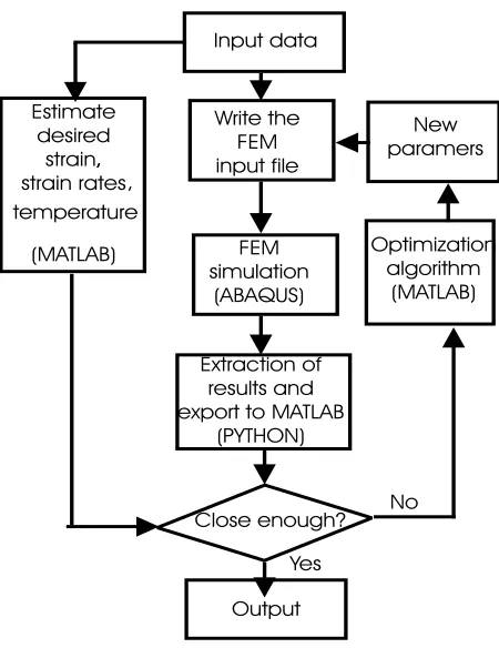
Figure 1: Illustration of design process.
[0, tm] into m partitions then the objective can be ex-pressed by
λ1min
Y
m+1 X
1
(εi−εi¯)2
+λ2min
Y
m+1 X
1
( ˙εi−εi¯˙)2
+λ3min
Y
m+1 X
1
(Ti−Ti¯)2
(21)
Further if we want to consider die life and flow balance then the Equations (12) and (14) can be included as con-straints with the objective function (21).
4
Schema of the design
Let us now consider the technical design details of the algorithm to solve Equation (21). The solution will be arrived at through several steps as shown in Figure 1. They consists of:
(i) The input data define the physical structure by its dimensions, material properties and boundary con-ditions.
(ii)
M
ATLAB’s lsqnonlin optimization algorithm isap-plied to obtain the optimal values of strain-rate, strain values and temperature for given microstruc-ture properties of the material.
(iii) Input file module creates a model for the finite ele-ment analysis. It consists of geometry of the model, material properties, contact definitions and loading sequence etc. This is done with a
M
ATLAB scriptwhich creates an input file for the ABAQUS pro-gram. The reason for choosing this approach is the possibility of easy modification of the die geometry for each iteration process in the optimization routine.
(iv) FEM simulation part executes the created input file usingABAQUS explicit.
(v) Extraction module retrieves results from ABAQUS ODB database. Here the interface is set up between
M
ATLAB’s optimization procedure andABAQUSfi-nite element simulation. This is achieved through the use of PYTHON scripts to retrieve necessary results from the ODB database. It is saved in a different file with an EXCEL file format and then processed with
M
ATLAB to obtain the results foroptimization.
(vi) The optimisation part is implemented using
M
ATLAB’slsqnonlinbuilt-in function which uses theLevenberg-Marquardt algorithm. This approach en-sures an easy implementation of multiple runs of ABAQUS within an optimization routine.
Unlike the linear problem, the non-linear objective func-tion given by Equafunc-tion (21) may have more than one minimum. Therefore, the solution process should include finding the global minimum. To deal with these problems we first find all or most of the local minima of (21) for a sequence of design variables at a larger interval. Then we pick the lowest value of the minima. In the next step we use the minimum obtained from the previous step as the starting value to solve Equation (21).
5
Results and discussion
In order to study the optimum results in an aluminium extrusion process, a FE-simulation is carried out using MATLAB and ABAQUS. The process here is a hot ex-trusion process with heat transfer between the work piece and die also being considered. The work piece and die has an initial temperature ofT = 450oC. The extrusion ratio is 1.33. The friction factor at the die-material in-terface is assumed to be 0.1. The die is considered as a deformable body. Ram velocity is 6.25mms−1. The flow stress-strain relationship of the work-piece material is [7]
¯
σ= 209 (¯ε)0.122N/mm2
(22)
Other data values used in the simulation of the work-piece are: Young’s modulus ofE = 7×10¹⁰ P a, coefficient of
= 204 W m−1K−1 when T = 0 oC, = 225 W m−1K−1 whenT = 300oCand the values used for the die material are Young’s modulus of E= 20×1010
P a, coefficient of expansion= 8.4×10⁻⁵ oC−1 at T = 20 oC, Poisson’s ratio= 0.30, inelastic heat fraction = 0.9, specific heat = 450 Jkg−1K−1, density= 7200 kgm−3, conductivity = 204 W m−1K−1 when T = 0 oC, = 225 W m−1K−1 whenT = 300oC.
First we minimized extrusion pressure, die pressure, temperature variation inside the deformation zone, velocity variation at the die exit, distortion variation, strain variation and strain rate variation at the die exit separately to study how each property vary with the process and design parameters. It is interesting to find that the optimal parameter values were not the same (eg the parameter which minimizes the extrusion pressure is not same as the parameter which minimizes temperature variation inside the die) for all categories.
Secondly we compared the circumferential and axial stress at the die exit. It has been found that the die which minimizes the strain rate variation at the exit also produces the profile with lowest circumferential stress and the die which minimizes the extrusion pressure produces the profile with minimum axial stress, which can be ex-pected. The review of literature [3] showed that the possi-bility of cracking increases with increasing tensile circum-ferential stresses and chevron(or central) bursts increase with increasing axial stress. Therefore it is important and necessary to include the minimization of circumferential and axial stress during the optimization process.
The tendency toward chevron cracking increases if plas-tic zones do not meet together inside the forming zone. If this happens the hydrostatic pressure at that region is zero. It can be shown that the hydrostatic pressure is not zero inside the forming zone for any of the above mentioned cases (which minimizes extrusion pressure, die pressure, temperature variation, strain rate variation etc) and in certain non optimal values (eg when extrusion pressure is maximum) the hydrostatic pressure inside the forming zone is zero.
Average grain size is proportional to
d α =
˙¯ εexp
Q
RT
β
. (23)
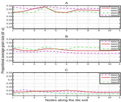
[image:5.595.323.521.78.246.2]The variation of four most optimized d/α values along the die exit with different process conditions are shown in Figure 2. Most optimal (in terms of uniformity)d/α val-ues of four different cases and their respective die surfaces which gives the optimum are shown in Figure 3. These figures clearly show that the grain size is more sensitive to extrusion speed and the initial temperature than the die geometry. Further the uniformity of the grain size is more influenced by the shape of the die surface than
1 2 3 4 5 6 7 8 9 10 11
0.22 0.24 0.26 0.28 0.3 0.32 0.34
A
1 2 3 4 5 6 7 8 9 10 11
0.22 0.24 0.26 0.28 0.3 0.32 0.34
B
Proportional average grain size (d/
α
)
1 2 3 4 5 6 7 8 9 10 11
0.22 0.24 0.26 0.28 0.3 0.32 0.34
Nodes along the die exit C
data1 data2 data3 data4
data1 data2 data3 data4
data1 data2 data3 data4
Figure 2: Grain size variation along the die exit (d/α) (A) when v = 6.3 mm/s, TD0 = 450
oC, TB
0 = 500
oC, (B) when v = 25 mm/s, TD0 = 450
oC, TB
0 = 500
oC, (C) when v= 25mm/s,TD0= 400
oC,TB
0 = 450
oC.
1 2 3 4 5 6 7 8 9 10 11
0.22 0.24 0.26 0.28 0.3 0.32 0.34
Nodes along the die exit A
a (v=6.3 mm/s, TD0=450,TB0=500)
b(v=25 mm/s TD0=450, TB0=500)
c(v=25 mm/s, TD0=400, TB0=450)
d(v=6.3 mm/s,TD0=450, TB0=500
Proportional average grain size (d/
a
)
B
a (v=6.3 mm/s, TD =450,TB =500) b(v=25 mm/s TD =450, TB =500)
c(v=25 mm/s, TD =400, TB =450)
d(v=6.3 mm/s,TD =450, TB =500
[image:5.595.315.542.339.664.2]initial temperature or ram speed.
Finally we looked at the grain size variation with various desired grain sizes for a sequence of design and process parameters and found that values of parameters (design and process) exist to satisfy equations (22), (18), (16) and (17).
6
Summary
The goal of the work presented here is to investigate a numerical technique which is capable of simultaneously estimating the optimal die profile and the process param-eters such as extrusion speed and initial temperatures. The approach is based on a non-linear least squares esti-mation using the desired properties of the product which is extruded.
The examples considered in the above section describe how values of the design and process parameters influ-ence the optimization process. The results from these examples suggest that the proposed technique is capable of estimating the optimal values reasonably well.
The validity and effectiveness of this technique has to be verified using an experimental method. We will address this issue as part of the ongoing project.
References
[1] Lee S. K., Ko D. C., Kim B. M., “Optimal die profile design for uniform microstructure in hot extruded product”,International Journal of Machine Tools & Manufacture, V40, pp.1457–1478, 2000.
[2] Mathews j. H., Fink K. D.,Numerical Methods Using Matlab, Prentice-Hall Inc, 4-th Edition, 2004.
[3] Shivpuri R., “Advances in numerical modelling of manufacturing process”, TransIndian Inst Metals, V57, pp.345–366, 2004.
[4] Venugopal S., Rodriguez P., “Strategy for the de-sign of thermomechanical processes for AISI type 304L stainless steel using dynamic materials model stability criteria and model for the evolution of mi-crostructure”, Journal of Materials Science, V39, pp.5557–5560, 2004.
[5] Venugopal S., Medina E. A., Malas I., Medeiros S., Frazier W. G., “Optimization of microstructure during deformation processing using control the-ory principles”,Scripta materialia, V36, pp.347–353, 1997.
[6] Wifi A. S., Shatla M. N. Abdel-Hamid A., “An optimum-curved die profile for the hot forward rod extrusion process”, Journal of Materials Processing Technology, V73, pp.97–107, 1998