Abstract—Reversible (invertible, lossless) authentication draws much attention recently for its ability to restore the original image from marked image without any distortions upon verification. In this paper, we propose a reversible water- marking scheme for image authentication based on histogram modification in integer wavelet transform (IWT) domain. The proposed scheme has features: i) Reversibility, high embedding capacity, and good perceptual invisibility; ii) Tamper localiza- tion and discerning; iii) Detection without requiring explicit knowledge of the original image; iv) Verification before recon- struction of the original image, therefore computational require- ments are reduced when reconstruction isn’t needed. To our best knowledge, none of the reversible authentication schemes reported in the literature has all of the features. Those features make the proposed scheme practical, effective and appealing for strict content integrity authentication system. Experimental results demonstrate the feasibility and validity of the proposed scheme.
Index Terms—Digital Watermarking, Fragile Authentica- tion, Image Integrity, Reversible Data Hiding, Tamper Localization.
I. INTRODUCTION
Since digital images are widely used nowadays and even an amateur can easily modify an image and create “perfect” forgeries with powerful image processing software, the need of originality and integrity or credibility check for images is raised in law, commence, defense, and journalism desirably. Fortunately, image authentication technique achieves such a goal.
Digital signature and digital watermarking are the two approaches for image authentication reported in the literature. The former is the traditional authentication methods and has some drawbacks. As the signature is appended to a digital image, it not only increases the file size but also can be removed easily. When facing format conversion, the authentication code will be lost. Moreover, it can not locate the tampered area of an image with high accuracy. The latter overcomes the above drawbacks and provides additional functionality. By embedding a watermark into digital image, the file size keeps unchanged. This watermark is very sensitive to any modifications imposed upon an image and can be used for tamper localization with high accuracy. However, conventional watermarking techniques distort the original image permanently. That is, the original image can not be recovered from the marked
Manuscript received July 21, 2008.
Xiaoping Liang was with the Guangdong Province Key Laboratory of Information Security, Sun Yat-Sen University, Guangzhou, China, now is with the Information Security Laboratory, Department of Information Engineering, The Chinese University of Hong Kong, Hong Kong (phone: 852-2609-8482; fax: 852-2609-5282; e-mail: [email protected]).
image when the marked image is deemed authentic. These distortions are not allowed in some sensitive applications, such as law enforcement, medical and military image systems. Reversible water- marking is a solution to those cases. As long as the marked image is authentic, the original image can be reconstructed without any distortion. Reversible watermarking techniques can be classified into three categories [1]: 1st, those for fragile authentication, 2nd,
those for high embedding capacity, and 3rd, those for
semi-fragile authentication. The second category may be applied to secret communication, and the third category to media such as for entertainment, which allow the marked media be stored in lossy-compression format, and be deemed authentic though it underwent common signal processing which keeps the content of the disturbed media. The first category is suitable for content that every bit is too important to neglect, i.e. require bit-by-bit exactness in special scenarios. We call the first category reversible authentication watermarking (RAW), where reversibility of the original media bit-by-bit makes sense.
An effective authentication scheme basically should have the desirable features [2]–[4]: tamper detection and localization, good perceptual invisibility, and detection without requiring explicit knowledge of the original image. Some RAW schemes for image have been reported in the literature [5]–[11], whereas rare of the schemes satisfy all the basic desirable features. Except the scheme proposed by Celik et al [10]–[11], none of the schemes in the literature provides tamper localization capability, which plays very important role in image authentication. Celik et al. utilized the hierarchical authentication watermark [12] in conjunction with the lossless generalized-LSB data embedding algorithm [13] to offer localized lossless authentication watermark. Beside tamper localization, another distinct advantage of the scheme proposed by Celik et al. over all the other existing RAW schemes is that it allows validation of the marked image before recovery of the original image, which is a new framework, hence reduce computational requirements in situations when either the verification step fails or the lossless restoration is not needed. However, the scheme relies on the context-based, adaptive, lossless image codec (CALIC) lossless image compression algorithm [14]–[15] to make space for embedding payload to achieve reversibility, thus it adds complexity to the implementation of authentication system, and may be inapplicable in case the original image has complex texture. Moreover, the quantized values of the original image are required as side information to reconstruct the original image. Tamper localization of the scheme is provided by the block-based nature of the algorithm, and the block size couldn’t be too small in order to perform the CALIC lossless image compression successfully. Hence, the accuracy of tamper localization is restricted. In
Reversible Authentication Watermark for Image
addition, the scheme couldn’t discern tamper originally done in frequency domain from that originally done in spatial domain, there- fore, any tamper originally done in frequency regions results in tamper localization in spatial regions of the image, i.e. it is deemed that the tamper is originally done in spatial domain. An example for illustration will be given in Section III.
Based on our prior work in the 2nd and the 3rd category of
reversible watermarking [16]-[18], we present a RAW scheme for image to cater for the need of strict content integrity authentication in this paper. The proposed scheme satisfies all the basic desirable features, and allows validation before reconstruction of the original image. The proposed scheme has three advantages over the scheme proposed by Celik et al. Firstly, reversibility and high embedding capacity are guaranteed by the statistical property of coefficients in high frequency sub-bands and histogram modification in IWT domain, and don’t rely on any lossless compression technique, hence the proposed scheme is easy to implement and has low computational complexity. Secondly, by exploit- ting the space-frequency localization property of IWT and combining a bi-level image and hashes of IWT coefficients as watermark, the scheme can discern tamper originally done in frequency domain from that originally done in spatial domain. Thirdly, the detector doesn’t require explicit knowledge of the original image, and therefore, verification and reconstruction of the original image can be performed only with secret key.
The rest of this paper is organized as follows. The proposed RAW scheme for image is described in Section II. Tamper discerning and security consideration are presented in Section III. Some experimental results are presented in Section IV. The conclusion is drawn in Section V.
[image:2.612.314.540.289.506.2]II. THE PROPOSED RAW SCHEME FOR IMAGE
Fig. 1 Reversible authentication watermarking (RAW) framework. (a) Reversible authentication watermark embedding; (b) Watermark verification and image reconstruction.
The whole framework of the proposed RAW scheme is shown in Fig. 1. The reversible authentication watermark embedding phase at sender end is shown in Fig. 1(a), which is composed of three parts: pre-processing, authentication watermark embedding, and post-processing. The watermark verification and image reconstruction phase at receiver end is shown in Fig. 1(b), which is also composed of three parts: pre-processing, watermark verification, and image reconstruction, where the final part is optional. In the former phase, authentication watermark should be formed and embedded reversibly into subbands of IWT. In the latter
phase, authentication watermark should be extracted, and the original image may be reconstruction. Reversible watermarking method adopted in the proposed scheme to embed and extract authentication watermark is based on our prior work [16], which belongs to the 2nd category of the
reversible watermarking technique.
A. Reversible Authentication Watermark Embedding
Pre-processing. In order to avoid overflow/underflow, first we narrow the range of pixel value of the original image before IWT decomposition is done to it. Let G be narrowing value we set, x and 'x be pixel of 8-bits depth before and after the following modification
{
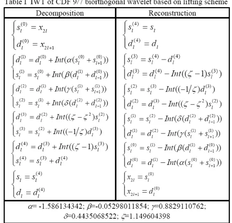
xx''= −= +x Gx G, if , if xx∈∈[255[0, ]G−G, 255], (1) Hence the range of pixel value is changed from [0, 255] to [G, 255-G]. We save the modified pixels as SM. [image:2.612.73.298.453.566.2]In the light of [20]–[21], we construct IWT of CDF 9/7 biorthogonal wavelet based on lifting scheme as shown in table I, which includes decomposition and reconstruction.
In table I, {xl}l∈Z is pixel sequence of the image. sl and dl
are generally referred to as lower frequency and detail coefficients (i.e. high frequency coefficients), respectively.
( )i l
s , ( )i l
d (i=0, 1, 2) are mid-output. Int(x) means integer part of x. α, β, γ, δ and ζ are parameters. After the 3rd-level IWT
decomposition is done on the pre-processed image, we get ten subbands that are labeled as HH1, HL1, …, LH3 (HH, HL
and LH stand for the horizontal, vertical, and diagonal detail subband respectively, and subscript number stands for resolution level), and LL3 which denotes approximation
coefficients. Coefficient value is denoted as c.
Authentication Watermark Embedding. The authentica- tion watermark is composed of bi-level image I that has visual meaning, four hashes of IWT coefficients of different subbands, overhead information Oinf that indicates information relating to reversible data hiding in the 1st-level
authentication watermark are embedded into different subbands.
Firstly, we calculate hashes on four sets {HH1, HL1, LH1},
{HH2, HL2, LH2}, {HH3, HL3, LH3}, and {LL3} using MD5,
and get h1, h2, h3, and h4 respectively. We concatenate the four hashes to form Hs.
Secondly, we process the bi-level image I with size adjustment and encryption, and then embed it into one of the 2nd-level subbands. We adjust I to the same size with the
2nd-level subband by image scaling in order to maintain high
accuracy of tamper localization, and then we encrypt I using stream cipher with a secret key K as seed and get I*
{
* ( )
K seed
I I PRNG seed
→
= ⊕ , (2)
where PRNG is pseudo-random number generator [21]. Then we embed I* into one 2nd-level subband by replacing
LSBs. The 2nd-level subband is selected by the same key K
for simplicity. Note that the same secret key K will be used in this authentication watermark embedding part for simplicity. The original LSBs replaced by I are recorded as O2. Note that if the high frequency coefficient value c is -1, and the to-be-embedded bit is ‘0’, c changes to 0 after bit replacement, and the restored c will be 1 according to O2. We create a one-bit bitmap BM2 as the location map of c to solve the problem. When c has value -1 and is replaced by ‘0’, value 1 is assigned to the corresponding bit location of BM2, otherwise value 0 assigned. Because BM2 has many sequential 0 values, it can be losslessly compressed by run-length encoding (RLE) to spare embedding capacity, and denoted as BM2C after compression.
Thirdly, because all data except I is embedded into the 1st-level subbands, we evaluate the embedding capacity Cap
by summing up all the peak amplitude P and/or sub-peak amplitude P' of the three 1st-level subbands
1 1 1
1 1 1
mode 1
mode 2 mode 1
,
' ' '
HH HL LH
HH HL LH
Cap P P P
Cap Cap P P P
−
− −
= + +
⎧⎪
⎨ = + + +
⎪⎩
(3) where the subscript stands for embedding mode or the label of the 1st-level subband. According to bit-length len of all the
data to be embedded, e.g. G, SM, Hs, O2, BM2C, and header
that will appear in the next step, we choose embedding mode-1 if len ≤Capmode-1, otherwise we choose embedding
mode-2. As a rule of thumb, embedding mode-1 or mode-2 is enough for the most cases. We record the chosen embedding mode that is denoted by several bits, and the coefficient values corresponding to P and P' of the 1st-level subbands as
overhead information Oinf.
Fourthly, we embed Oinf into selected coefficients of selected sub-band from {HH3, HL3, LH3, LL3} by replacing
LSBs. The sub-band and the coefficients in the sub-band are selected according to the secret key K. The original selected LSBs replaced by Oinf are recorded as O3, and the location bitmap as BM3. Because the length of BM3 is short, lossless compression isn’t needed. If LL3 is selected, bitmap only has
value 0 because all low frequency coefficient values are larger than 0.
Fifthly, we form bit-stream Bs as
Bs= ∪G SM∪Hs∪O2∪BM2C∪O3∪BM3, (4) and encrypt it using the secret key K as follows
{
BsK*→=seedBs⊕ PRNG seed( ). (5) We form B asB=header∪Bs*, (6) where header indicates bit-length of every part of Bs*. In our experiment, the bit-length of header is 80 bits.
Finally, we embed B into the 1st-level subbands using
reversible data hiding algorithm based on histogram modification of wavelet coefficients.
Reader may refer to [16] for detail on the above embedding capacity evaluation and reversible data hiding, which includes both reversible data embedding that has been exploited above, and data extraction and restoration that will be exploited in the following watermark verification and image reconstruction phase.
Post-processing. We perform the 3rd-level IWT reconstruct-
ion to form the authenticable marked image, and check whether any over/under-flow happens. If it does, we increase the value of G, and go back to pre-processing part, and go through the phase again; if it doesn’t, we get the authenticable marked image.
B. Watermark Verification and Image Reconstruction
As opposed to previous reversible authentication schemes that required reconstruction of the original image prior to validation, the proposed RAW scheme allows validation of the marked image before reconstruction of the original image (see Fig. 1(b)), hence reduces computational requirements in situations when either the verification step fails or the lossless restoration is not needed.
Pre-processing. The 3rd-level IWT decomposition is done on
the to-be-authenticated image, and we get ten subbands that are labeled as HH'1, HL'1, …, LH'3.
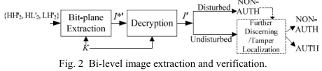
[image:3.612.311.541.478.529.2]Watermark Verification. This part includes two stages, i.e. bi-level image extraction and verification, shown in Fig. 2, and further discerning/tamper localization.
Fig. 2 Bi-level image extraction and verification.
In the first stage, the bi-level image I*' is extracted from LSBs of one 2nd-level subband according to the secret key K,
i.e. bit-plane extraction, and decrypted as follows
{
*' ( )
'
K seed
I I PRNG seed
→
= ⊕ . (7)
stage, the image is authentic, otherwise non-authentic. If the image is deemed authentic, we go to the final part, i.e. image reconstruction, and the original image is reconstructed without any distortion. If the image is deemed non-authentic, the procedure is ended, or the tampered image is restored with distortion according to user’s choice. Hence, computational requirements may be reduced.
In the second stage, firstly, overhead information O'inf is
extracted from LSBs of one 3rd-level subband according to
the secret key K, and we obtain the embedding mode and the coefficient values corresponding to P and/or P' of the 1st-level subbands. Secondly, by the overhead information
we extract bitstream B' from the 1st-level subbands, and
restore the 1st-level subbands simultaneously. Thirdly, we
decrypt Bs*' and get Bs' as follows
{
' *' ( )
K seed
Bs Bs PRNG seed
→
= ⊕ , (8)
and parse Bs' with header information, and obtain G', S'M, Hs', O'2, BM'2C, O'3, and BM'3. Fourthly, we restore the
3rd-level subband which O'
inf is extracted from by replacing
LSBs with O'3 by the aid of BM'3, and restore the 2nd-level
subband which I*' is extracted from by replacing LSBs with
O'2 by the aid of BM'2, which is decompressed from BM'2C
according to RLE. Coefficients with value 1 are restored to -1 when their position marked by the location bitmap is ‘1’. Fifthly, we recalculate hashes on the four sets {HH'1, HL'1,
LH'1}, {HH'2, HL'2, LH'2}, {HH'3, HL'3, LH'3}, and {LL'3}
using MD5, and get hr1, hr2, hr3, and hr4 respectively, then compare them with the extracted h'1, h'2, h'3, and h'4. If
hri=h' , for all i i∈[1, 4], (9) the image is deemed authentic without any distortion, and we go to the final part, i.e. image reconstruction, else if
hri≠h' , for at least one i i∈[1, 4], (10) the image is deemed a forgery and non-authentic.
Image Reconstruction. If the image has passed the above authentication, we perform the 3rd-level IWT reconstruction
on the ten subbands, and restore the pixels with the extracted
G' and S'M, and therefore get the original image without
distortion.
III. TAMPER DISCERNING AND SECURITY CONSIDERATION One advantage of the proposed RAW scheme is that it can discern tamper originally done in frequency domain from that originally done in spatial domain. Here we give an example to show the discerning capability of the proposed RAW scheme in comparison with that of the scheme proposed by Celik et al [10]-[11]. We set the LSBs of a rectangle region with size 50x50 coefficients to zero in the center of subband {HH1} of Lena, see Fig. 3(a), i.e. tamper in one high
frequency subband artificially. Tamper done in {HH1} is
discerned by hash comparison in the proposed RAW scheme. In addition, discerning precision can be improved by calculating hash of every subband instead of subbands with the same resolution level. However, tamper originally done in spatial region instead of frequency region is the detection result of the scheme proposed by Celik et al [10]-[11], see Fig. 3(b), though the tampered image has no artifacts. In Fig. 3(b), the white pixels denote the pampered region in spatial
domain of the image under authentication, and the black pixels denote the regions without any tamper.
As to security, we choose stream cipher instead of block cipher, because stream cipher is more suitable than block cipher in this application, i.e. bit-stream encryption. In the proposed RAW scheme, the secret key is used to encrypt the to-be-embedded bi-level image and bit-stream, and to select sub-band of IWT to embed data. Using the same secret key is for convenience of the user, simplicity and practicability of the authentication system. To enhance security, one secrete key is used for one image or a group of images in the proposed RAW scheme. This is a bit like One-time Pad, hence it is very difficult for a would-be attacker to get the right key. Moreover, more than one secret key may be used for one image in order to enhance system security. In addition, hashes are used to discern tamper. Any change made to the to-be-authenticated image will change the recalculated hash and/or the extracted hash. The probability of obtaining a match of the recalculated hash and the extracted hash is comparable to finding a collision for the hash. Hence it is difficult for attacker to get the right secret key and a match simultaneously, i.e. it is difficult to forge an image passed the authentication system.
Fig. 3 (a) The tampered image; (b) Detection result where white pixels denote the tampered regions.
IV. EXPERIMENT RESULTS
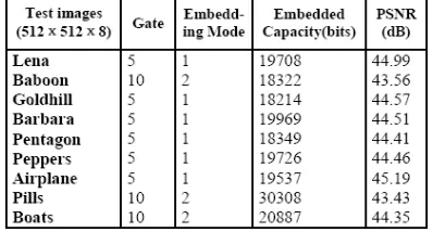
We applied the proposed RAW scheme to lots of grayscale images, and some examples that are frequently used are listed in Fig. 4. Table II contains experimental results of the listed images. In this table, embedding capacity means the total length of bit-stream including header, and PSNR is defined as
wherex n m( , )is pixel of original image with size ofN M× , and '( , )x n m the pixel of the marked image. Embedding capacities of every image in table II are different, because overhead information is different for every test image generally. Table II indicates that the proposed RAW scheme keeps low distortion between marked image and the original one measured by PSNR.
Fig. 5 shows the visual impact of the proposed RAW scheme on grayscale images Pentagon and Airplane. It indicates that the marked image of the proposed RAW scheme has good visual quality.
Fig. 6 shows the tamper localization capability of the proposed RAW scheme. The disturbed regions of the
(
2 1 2)
1 1
10log 255 N M ( '( , ) ( , )) ( )
n m N M
[image:4.612.328.525.324.421.2]extracted bi-level image denote the tamper regions of the marked images. Fig. 6(a) shows the cut and replacement operation using commercial image editing software in the center section of the marked image. Fig. 6(b) shows the modification on text printed on airplane body. Fig. 6(d) and (e) show the detection results. The figure indicates that the proposed RAW scheme can detect malicious modifications and locate the tampered regions with high probability.
V. CONCLUSION
A new reversible authentication watermark scheme is presented in this paper. The proposed RAW scheme exploits the statistical property of coefficients in high frequency sub-bands of IWT to ensure enough reversible embedding capacity. The proposed RAW scheme utilizes the space-frequency localization of IWT, and combining a bi-level image and hashes on IWT coefficients to discern and localize tamper originally done in spatial or frequency regions. In addition, the detector doesn’t require explicit knowledge of the original image to verify the marked image and reconstruct the original one. Moreover, the proposed RAW scheme performs verification before reconstruction of the original image, in that way computational requirements can be reduced. To improve the security of the proposed scheme, stream cipher with secret key and hashes are used simultaneously. With those advantages, the proposed RAW scheme is practical and effective, and can be applied to strict content integrity authentication system in law, commence, defense, and journalism.
ACKNOWLEDGMENT
X. Liang thanks Prof. Jiwu Huang for his valuable comments, and thanks student Zhenhua Qu for carrying out part of the experiment. Both Jiwu Huang and Zhenhua Qu are with Guangdong Province Key Laboratory of Information Security, Sun Yat-Sen University, Guangzhou, China.
REFERENCES
[1] Y. Q. Shi, “Reversible data hiding,” Third International Workshop on Digital Watermarking, Lecture Notes in Computer Science, vol. 3304, 2005, pp. 1−12.
[2] E. T. Lin and E. J. Delp, “A Review of Fragile Image Watermarks,”
Proceedings of the Multimedia and Security Workshop (ACM Multimedia’99) Multimedia Contents, Oct. 1999, pp. 25−29.
[3] M. Wu and B. Liu, “Watermarking for image authentication,” Procee- dings of the IEEE International Conference on Image Processing, vol. 2, Oct. 1998, pp. 437−441.
[4] D. Kundur and D. Hatzinakos, “Digital watermarking for telltale tamper proofing and authentication,” Proceedings of the IEEE, vol. 87, no. 7, July 1999, pp. 1167−1180.
[5] J. M. Barton, “Method and apparatus for embedding authentication information within digital data,” US Patent 5,646,997, 1997. [6] C. W. Honsinger, P. Jones, M. Rabbani, and J. C. Stoffel, “Lossless
recovery of an original image containing embedded data,” US Patent 6,278,791, 2001.
[7] J. Fridrich, M. Goljan, and R. Du, “Invertible Authentication,” Procee- dings of SPIE, vol. 3971, Jan. 2001, pp. 197−208.
[8] J. Fridrich, M. Goljan, and R. Du, “Invertible Authentication Water- mark for JPEG Images,” Proceedings of IEEE ITCC, April 2001, pp. 223−227.
[9] J. Tian, “Wavelet-based Reversible Watermarking for Authentication,”
Proceedings of SPIE, vol. 4675, 2002, pp. 679-690.
[10] M. U. Celik, G. Sharma, E. Saber, and T. A. Murat, “Localized Loss- less Authentication Watermark,” Proceedings of SPIE, vol. 5002, 2003, pp. 689-698.
[11] M. U. Celik, G. Sharma, and A. M. Tekalp, “Lossless watermarking for image authentication: A new framework and an implementation,” IEEE Trans. Image Processing, vol. 15, no. 4, April 2006, pp. 1042 -1049. [12] M. U. Celik, G. Sharma, and E. Saber, A. M. Tekalp, “Hierarchical
Watermarking for Secure Image Authentication with Localization,”
IEEE Trans. Image Processing, vol. 11, no. 6, June 2002, pp. 585-595. [13] M. U. Celik, G. Sharma, A. M. Tekalp, and E. Saber, “Lossless
generalized-LSB data embedding,” IEEE Trans. Image Processing, vol.14, no.2, Feb. 2005, pp. 253-266.
[14] X. Wu and N. Memon, “Context-based, adaptive, lossless image codec,” IEEE Trans. Commun., vol. 45, no. 4, April 1997, pp. 437-444. [15] X. Wu, “Lossless compression of continuous-tone images via context
selection, quantization, and modeling,” IEEE Trans. Image Process- ing, vol. 6, no. 5, May 1997, pp. 656–664.
[16] X. Liang, X. Wu, and J. Huang, “Reversible Data Hiding for Image Based on Histogram Modification of Wavelet Coefficients”,
International Conference on Computational Intelligence and Security (CIS), Lecture Notes on Artificial Intelligence (LNAI), vol. 3802, Dec. 2005, pp.Ⅱ573-580.
[17] X. Wu, X. Liang, H. Liu, J. Huang and G. Qiu, “Reversible Semi-fragile Image Authentication using Zernike Moments and Integer Wavelet Transform,”, Int. Conf. on Digital Rights Management: Technologies, Issues, Challenges and Systems, Lecture Notes on Computer Science (LNCS), vol. 3919, July 2006, pp. 135-145. [18] X. Liang, W. Liang and W. Zhang, “Reversible Semi-fragile
Authentication Watermark,” Proceedings of the IEEE International Conference on Multimedia and Expo (ICME’07), July 2007, pp. 2122-2125.
[19] I. Daubechies and W. Sweldens, “Factoring wavelet transform into lifting step,” Journal of Fourier Analysis, vol. 4, 1998, pp. 245-267. [20] R. Calderbank, I. Daubechies, W. Sweldens, and B. L. Yeo, “Wavelet
transforms that map integers to integers,” Journal of Applied and Computational Harmonic Analysis, vol. 5, 1998, pp. 332-369. [21] D. R. Stinson, Cryptography Theory and Practice (3rd ed.). Boca
[image:5.612.313.543.392.522.2]Raton: Chapman & Hall/CRC, 2006, pp. 323-349.
Fig. 4 Some of test images with size of 512×512.
[image:5.612.328.527.546.653.2](a) (b)
Fig. 5 Marked grayscale images (a) Pentagon, PSNR=44.41dB, 18349bits embedded; (b) Airplane, PSNR=45.19dB, 19537bits embedded.
[image:6.612.73.296.191.384.2]