Abstract—A new technological approach for direct heating of
large volumes of contaminated soil using radio-frequency (RF) energy is described. The method can be used to thermally enhance a variety of remediation techniques such as biodegradation and soil vapour extraction. The technical basis, a container-based modular and mobile radio-frequency platform is presented and the benefits of this platform working under harsh field conditions are demonstrated. Additionally, aspects of electromagnetic compatibility, system reliability and safety are discussed.
Index Terms—Radio Frequency Heating, Electromagnetic
compatibility, Heterogeneous communication architecture, Safety
I. INTRODUCTION
Dielectric heating using radio-frequency (RF) energy is a new technological approach to heat large volumes of contaminated soil and other materials in order to support various remediation technologies, namely biodegradation and soil vapour extraction (SVE) [1]. Among thermal in situ remediation methods being capable to enhance the efficiency and cost-effectiveness of remediation processes, direct RF heating has some unique advantages as it can be applied for a variety of soils (including sandy and tenacious ones independent of their humidity) and is very flexible with respect to the final temperatures and heating rates. Therefore, it may be applied in combination with several remediation techniques covering a wide temperature range (up to more than 400°C) [2]. The working principle is similar to that of a microwave oven. The temperature increase is caused by the rapid reorientation of dipoles and surface charges in the external electromagnetic field (RF field). However, due to lower frequencies (in the MHz range) much larger penetration depths and therefore a more-homogeneous heating even in the cubic metre scale can be realized. The utilization of an electronic matching network (so-called
Manuscript received July 18, 2009.
This work was funded by the German Federal Ministry of Education and Research under Grant 1781X05 (RFClean). Infrastructuralhelp, namely the test field site on the location of a former hydrogenation plant close to the city of Leipzig, was provided by the SAFIRA II program of the Helmholtz Centre for Environmental Research – UFZ which was also funded by the Germany Federal Ministry of Education and Research.
a: University of Applied Sciences (HTWK), Faculty of Electrical Engineering and Information Technology, Karl-Liebknecht-Str. 132, 04277 Leipzig, Germany, (corresponding author: [email protected])
b: Helmholtz Centre for Environmental Research – UFZ, Department of
matchbox) allows fitting of the variable impedance of the soil to the generator thus leading to a very efficient trans-formation of RF energy into heat in the desired material volume. The RF generator is housed in a container-based modular system which allows high mobility and flexibility.
When applied in combination with soil vapour extraction (SVE), the RF heating of soil has the positive effects to increase the vapour pressure of organic pollutants, to shift the adsorption equilibria towards desorption, to increase the water solubility and mobility of contaminants and to create ‘stripping effects’ associated with generation of steam from soil pore water. The gas flow through the soil induced by the SVE acts as an effective transport medium for the removal of contaminants but it also efficiently diffuses heat in the treatment volume thus creating a relatively homogeneous soil temperature profile.
This study focuses on the measurement and process control technology established for a demonstration field site on the location of a former hydrogenation plant close to the city of Zeitz in Germany being one basis of the application of the modular system at various field projects.
II. APPLICATION
The demonstration field site for testing soil remediation technologies, in particular thermally enhanced SVE technologies, was run under the SAFIRA II program (remediation studies in regional contaminated aquifers) of the Helmholtz-Centre for Environmental Research - UFZ.
The field site was characterized by a large scale soil contamination with high concentrations of BTEX, in particular of benzene, up to 4000 mg/kg in a depth from 4 to 10 m. RF heating was applied for several months to heat up a soil volume of about 300 m3 and to efficiently extract the contaminants with a SVE. High concentrations of organic pollutants (VOC) in the SVE effluent above the lower explosive limit of benzene were characteristic for that field site.
Crucial for the success of the RF soil remediation on this site beside engineering aspects regarding electrode design and SVE technology was the process measurement and control technology realized for this mobile RF platform. The measurement of a number of relevant process parameters like contaminant concentration, SVE gas flow, soil temperature,
Mobile Radio-frequency Platform for a
Thermally Enhanced Soil Vapour Extraction
RF power and reflected RF power and the application of these parameters as control variables for the RF generator were the basis for an automated operation of the RF platform for several months. A further very important aspect was the option of remote control during the long-term remediation.
III. SYSTEM CONCEPT
The RF test field site in Zeitz (Germany) mainly consisted of two 20 foot containers, one RF container and an office container as well as a catalytic combustion unit (fig. 1).
The RF heating was realized with one electrode (RF electrode) while the SVE was operated with three extraction
RF container
Office
RF-shielding
RF-electrode Matchbox Coaxial
cable
• Radio wave heating of the unsaturated zone up to 6 m depth, approx. 300 m³ soil volume • 4 combined RF-Electrodes / Extraction wells in a triangular arrangement with 3 m electrode distance • Measuring points for up to 50 temperature sensors
• Measuring points for soil vapour sampling
Test site for Radio wave heating of the unsaturated zone
Catal. combustion
Extraction wells Matchbox
RF-shielding
RF-Unit Catal.comb.
Picture at the RF test site with RF-shielding and matchbox in the foregrund and RF container and catalytic combustion in the back-ground
Coaxial cable
RF container
Office
RF-shielding
RF-electrode Matchbox Coaxial
cable
• Radio wave heating of the unsaturated zone up to 6 m depth, approx. 300 m³ soil volume • 4 combined RF-Electrodes / Extraction wells in a triangular arrangement with 3 m electrode distance • Measuring points for up to 50 temperature sensors
• Measuring points for soil vapour sampling
Test site for Radio wave heating of the unsaturated zone
Catal. combustion
Extraction wells Matchbox
RF-shielding
RF-Unit Catal.comb.
Picture at the RF test site with RF-shielding and matchbox in the foregrund and RF container and catalytic combustion in the back-ground
[image:2.595.100.512.60.333.2]Coaxial cable
Figure 1: Set up of the RF test field site in Zeitz, Germany
[image:2.595.119.490.492.749.2]wells around the RF electrode. Within the test field, numerous measuring points in different depths (3, 5 and 7 m depth) for soil temperature and soil vapour were located.
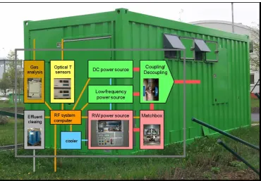
As already indicated in figure 1, the RF system consisted of several elements. The RF generator (IS15/13560, Huettinger Elektronik, Freiburg/Brsg.) was located in the RF container unit. The generator was connected with the matchbox (PFM 30000A, Huettinger Elektronik, Freiburg/Brsg.) by a coaxial cable. The matchbox was located directly above the RF electrode to minimize the distance between both and therefore also the necessary RF shielding around the RF electrode [1]. The connection between matchbox and RF electrode was realized by a thin copper band. The matchbox consisting of coils and adjustable vacuum capacitors allowed the total impedance of the tuned circuit including the soil to be fitted optimally to the RF generator. Therefore, electromagnetic energy can be guided into the soil efficiently without significant reflection.
The temperature measurement was continuously operated by means of non-metallic fibre optical sensors (Nortech Fibronic, Quebec, Canada and OPTOcon, Dresden, Germany).
The RF container unit itself was physically divided in two parts having an RF-technology and a measuring and process control room.
The RF technology room mainly containing RF generator, cooler and container power supply was completely encapsulated with thin stainless steel plates to minimize RF noise in the environment.
The core of the process measuring and control room was the RF system computer. The RF system control and operating software running on that computer continuously controlled and operated all important devices and processes and maintained an internet connection. Using this internet connection, the mobile RF platform could also be controlled from any other location, e.g. the home institutions of the project partners.
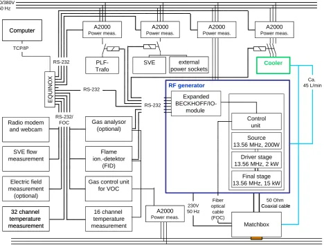
Furthermore, several other analytical measuring devices (gas and temperature monitors), the alarm system and the air conditioning control unit were located in process measuring and control room. The overall concept of the mobile RF platform is illustrated in figure 2, indicating also the possibility of combining high- (RF) and low-frequency power (power line frequency – PLF) for remediation tasks. This combination is especially used for homogeneous heating of the boundary layer between saturated (groundwater) and unsaturated zones in the soil.
32 channel temperature measurement Flame ion.-detektor (FID) Electric field measurement (optional) PLF-Trafo SVE Computer TCP/IP 50 Ohm Coaxial cable 230/380V 50 Hz A2000 Power meas. RF generator Control unit 16 channel temperature measurement RS-232 Source 13.56 MHz, 200W
Driver stage 13.56 MHz, 2 kW
Final stage 13.56 MHz, 15 kW
Matchbox Fiber optical cable (FOC) RS-232 Ca. 45 L/min E Q UINOX 230V 50 Hz A2000 Power meas. A2000 Power meas. A2000 Power meas. Cooler SVE flow measurement external power sockets RS-232/ FOC Expanded BECKHOFF/IO-module Gas analysor (optional) RS-232
Gas control unit for VOC A2000 Power meas. Radio modem and webcam 32 channel temperature measurement Flame ion.-detektor (FID) Electric field measurement (optional) PLF-Trafo SVE Computer TCP/IP 50 Ohm Coaxial cable 230/380V 50 Hz 230/380V 50 Hz A2000 Power meas. RF generator Control unit 16 channel temperature measurement RS-232 Source 13.56 MHz, 200W
Driver stage 13.56 MHz, 2 kW
Final stage 13.56 MHz, 15 kW
Matchbox Fiber optical cable (FOC) RS-232 Ca. 45 L/min E Q UINOX 230V 50 Hz A2000 Power meas. A2000 Power meas. A2000 Power meas. Cooler SVE flow measurement external power sockets RS-232/ FOC Expanded BECKHOFF/IO-module Gas analysor (optional) RS-232
Gas control unit for VOC
A2000 Power meas. Radio modem
[image:3.595.67.536.392.746.2]and webcam
IV. HETEROGENEOUS COMMUNICATION ARCHITECTURE
The process measurement and control system is illustrated in figure 3. A multitude of devices and processes were controlled. The up to now achieved level of the process measurement and control contained off:
- Controlling of the RF generator and the matchbox for different operation modes, in particular the RF output power by manual control, power setpoint control and temperature setpoint control.
- Data acquisition and storage as well as critical value control of soil temperatures, VOC concentrations, SVE gas flow (including gas pressure and gas temperature) and electric field strengths. Exceeding critical values of one of the aforementioned parameters led to an automatic shut-down of the RF system.
- Switching and control of several power sockets and integration of external or optional devices into the data acquisition by the expanded BECKHOFF input/output module.
- Text-messaging to a cell phone each time failures or undesirable operating states occurred.
- The control of several ‘soft’ and ‘hard’ security circuits (e.g. micro-switches on the container doors, motion detectors) and shut-down of the RF system by interruption of one of the security circuits. Integration of a webcam into the security system.
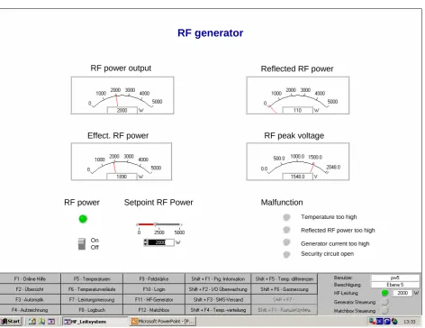
The RF system control and operating software had a distinct graphical user interface for each of the above mentioned control tasks. As example, the controlling interface of the RF generator power, is shown in figure 4. The RF generator interface allowed switching on the generator and adjusting the RF power to a desired level. Furthermore, it provided crucial information about the reflected RF power and the RF peak voltage which were both measured in the matchbox. Additionally, in case of failures in the RF system, distinct error messages were highlighted in that interface.
In a second interface, the matching network was controlled. Through this interface, the RF system could be operated either by an automatic or a manual tuning of the RF circuit by changing the capacitance of the vacuum capacitors in the matchbox. The automatic tuning took place by iterative mathematical algorithms to minimize the reflected RF power.
RF power output Reflected RF power
Effect. RF power RF peak voltage
RF power Setpoint RF Power Malfunction
Temperature too high
Reflected RF power too high
Generator current too high
Security circuit open On
Off
RF generator
RF power output Reflected RF power
Effect. RF power RF peak voltage
RF power Setpoint RF Power Malfunction
Temperature too high
Reflected RF power too high
Generator current too high
Security circuit open On
Off
[image:4.595.61.534.360.724.2]RF generator
V. ELECTROMAGNETIC COMPATIBILITY AND SAFETY
A major aspect when dealing with radio frequency is the electromagnetic compatibility (EMC).
The separation of RF relevant technology from computer and analytical devices in the RF container and the electromagnetic shielding of the RF technology room illustrate that EMC aspects were already very much within the focus during the constructional phase of the mobile RF platform. Furthermore, all power and data cables between the two rooms of the RF container were connected to various types of EMC filters, located within the wall between the two rooms.
Additional to those constructional measures several arrangements on the test field itself were taken to reduce parasitic RF noise:
- RF shielding made of steel plates in a box shape with a distance to the RF electrode of 1 m.
- Connecting a copper gage to the steel plates close to the ground and entrenching of that copper gage over a length of 0.5 m with wet sand.
- Realization of an air gap around the RF electrode up to the depth at which the RF soil heating was planned to take place [1,2].
[image:5.595.49.288.416.617.2]- Utilization of non-metallic pipes and tubes as well as non-metallic data cables (FOC).
Figure 5 shows the distribution of the electric field strengths on the test field around the RF electrode 1 m above the ground.
The highest field strengths of about 125 V/m were
measured close the extraction wells indicating that the electromagnetic field emitted from the RF electrode arrived at the metallic extraction wells, which themselves acted like week RF antennas. This RF radiation was not critical for short-time exposure. The overall electromagnetic radiation in the RF technology room of the RF container was very low (below 10 V/m). Since the remediation field site generally
and the access was allowed for instructed staff only, the issue of RF radiation was not of major concern referring to EMC and safety aspects.
VI. CONCLUSION
The demonstration field site for RF enhanced soil vapour extraction was a successful test for operating a relatively complex system for several months with a high level of automation and safety. By constructional means within the RF container but also by a new electrode design and shielding set up the RF radiation could be significantly reduced.
ACKNOWLEDGMENT
The authors acknowledge technical support provided by Thomas Minner and Carsten Koegler (Centre for Research and Technology Transfer - FTZ, Leipzig, Germany) relating to automation and sensor aspects.
REFERENCES
[1] U. Roland, D. Buchenhorst, F. Holzer, F.-D. Kopinke; Engineering aspects of radio-wave heating for soil remediation and compatibility with biodegradation; Environ. Sci. Technol. 42 (4), 2008, 1232-1237 [2] U. Roland, F. Holzer, F.-D. Kopinke, D. Buchenhorst, R. Koehler,
Verfahren und Vorrichtung zur selektiven dielektrischen Erwaermung eines Feststoffbettes mittels stabfoermiger Elektroden, Deutsches Patent DE 102005052276, Deutsches Patent- und Markenamt, Muenchen, 2008
E / V m-1
0
13
25
38
50
63
75
88
100
113
125 1 m
1 m
measuring points
E / V m-1
0 0
13
25
38
50
63
75
88
100
113
125 13
25
38
50
63
75
88
100
113
125 1 m
1 m
measuring points