Generating a Multiplying Factor to Determine
Capacitor Value for all Range of Power Factor
Correction in Industrial Environment
OSAFEHINTI, S I, AROBIEKE O.O. AMODU S B, and OLUSOLADE M A
Abstract - The paper highlights the methods of power
factor correction in improving electricity supply and tends the aspect of using shunt capacitor. A table to determine a multiplying factor for all range of power factor correction is generated. The product of the multiplying factor and the kilowatt rating of the industrial environment give the rated value of the capacitor needed to carry out the power factor correction operation.
KEYWORDS: Power factor correction, electricity supply,
shunt capacitor, kilowatt rating
I INTRODUCTION
Electrical Engineers involved with the generation, transmission, distribution and consumption of electrical power should have interest in the power factor of loads because it affect efficiencies and costs for both the electrical power supply industry and the consumers. In addition to the increased operating costs, reactive power can require the use of cable, switches, circuit breakers, transformers and transmission lines with higher current capacities
Manuscript received Feb 13, 2013; revised April 15, 2013
O O Arobieke is a Senior Lecturer with Rufus Giwa Polytechnic, Owo Nigeria email: [email protected] +2348167589732)
S I Osafehinti is a Senior Lecturer with Rufus Giwa Polytechnic, Owo Nigeria; (email: [email protected])
S B Amodu is aAsst Chief Technologist with Rufus Giwa Polytechnic, Owo Nigeria, (email: [email protected])
M A Olusolade is a Technical Instructor with Rufus Giwa Polytechnic, Owo Nigeria (email: [email protected])
Power factor correction brings the power factor of an AC power circuit closer to unity by supplying reactive power of opposite sign, adding capacitors which act to cancel the inductive effects of the load. The inductive effect
of motor loads may be offset by locally connected capacitors. Sometimes, when the power factor is (leading) due to (capacitive) loading, inductors (also known as ‘reactors’ in this context) are used to correct the power factor. In the electricity industry, inductors are said to consume reactive power and capacitors are said to supply it.
Instead of using a capacitor, it is possible to use an unloaded synchronous motor. The (reactive power) drawn by the synchronous motor is a function of its field excitation. This is referred to as a synchronous condenser. It is started and connected to the electrical network. It operates at full leading power factor and supply. Volt-amperes reactive /VARs into the network as required to support a system’s (voltage) or to maintain the system power factor at a specified level. The condenser’s installation and operation are identical to large electric motor. Its principal advantage in this case is that the amount of correction can be adjusted and it can behave like an electrically variable capacitor
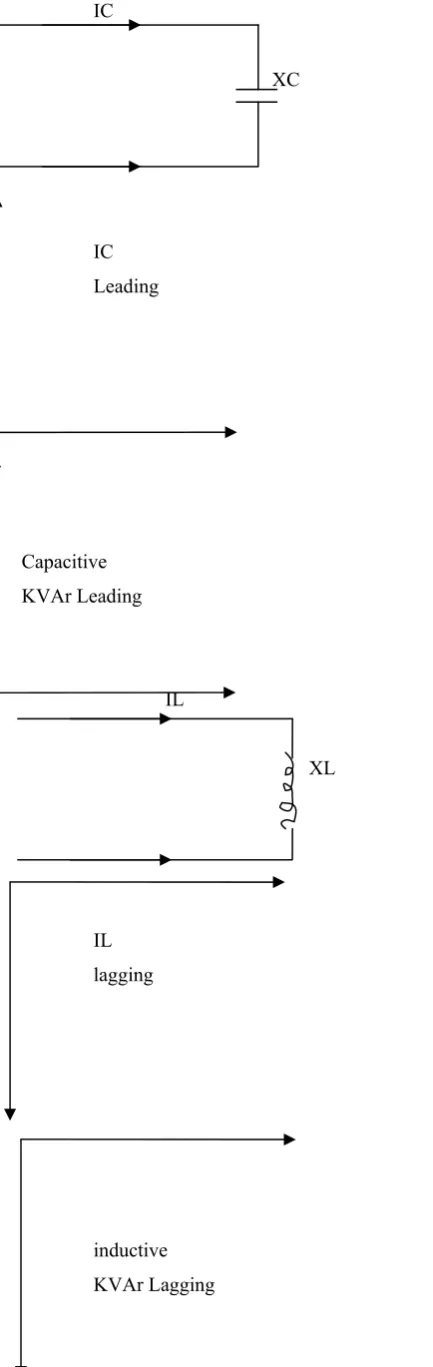
II BASIC CONSIDERATIONS 2.1 Fundamental Electrical Properties of capacitors and Inductors
IC
XC
IC Leading
Capacitive
KVAr Leading
IL
XL
IL lagging
[image:2.595.72.289.51.736.2]inductive KVAr Lagging
Figure 1: Voltage and Current Relations in a.c Circuits. X = reactance of the capacitor = 106/2πfC ohms
Where
f = supply frequency
C = capacitance in microfarads IC = current taken by the capacitor
= E/XC AMP Leading the applied voltage by 900 The reactive KVA taken by the capacitor
= EIc I0-3 KVAr = Ic2 Xc 10-3 KVAr
XL = reactance of the induction = 2πfl ohms Where
f = supply frequency L = inductance in henrys
IL = current taken by the inductor
= E/Xl amp lagging the applied voltage by 900 The reaction KVA taken by the inductor
= E Il 10-3 KVAr = Il Xl 10-3KVAr
Inductive reactance is opposite in sense to capacitive reactance. The active power (KW) taken by the capacitor or the inductor is zero.
III EFFECT OF INDUCTION MOTORS ON POWER QUALITY
Induction motor is the major load component of an industry. When connected to Electrical Power Source it draws current from the supply that is made up of resistive components and inductive components. The resistive components are:
(i) Load current (ii) Loss current
And the inductive components are: (iii)Leakage reactance (iv)Magnetizing current
motor. It is the catalyst that allows the motor to work properly. The magnetizing current and the leakage reactance can be considered as passive components of current that will not affect the power draw by the motor, but will contribute to the power dissipated in the supply and in the distribution system.
In the interest of reducing the losses in the distribution system, power factor correction is added to neutralize portion of the magnetizing current drawn by the motor.
IV POWER FACTOR CORRECTION PARAMETERS
Power factor correction SPFC is the process of adjusting the characteristics of electric loads in order to improve Power factor o that it is closer to unity (1) Power factor correction may be applied either by an (electrical power transmission) utility to improve the stability and efficiency of the transmission network: or correction may be installed by individual electrical customers to reduce the costs charged to them by their electricity supplier. A high power factor is generally desirable in a transmission system to reduce transmission losses and improve voltage regulation of the load.
V DETERMINATION OF SIZE OF CAPACITOR FOR IMPROVEMENT OF POWER
FACTOR
The load has a power factor Cos Ø1 and it is desired to raise the power factor to CosØ2 where Ø1 > Ø2
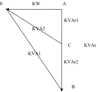
The power factor correction can be illustrated from power triangle. Thus, from figure 2 the power triangle OAB is for the improved power factor CosØ2. It may be seen that the Active power OA does not change with Power factor improvement.
However, the lagging KVAR of the load is reduced by the pf correction. Thus improving pf to CosØ2
Leading KVAR supplied by pf correction equipment = BC = CKVAR:
Where BC = AB – AC
Amount of compensation required = KVAR1 – KVAR2 Analytically, CKVAr = OA(Tan1 – TanØ2)
= KW (TanØ2 TanØ2)
0 KW A
KVAr1 KVA2
C KVAr KVA1
KVAr2
[image:3.595.310.514.66.257.2]B
Figure 2: POWER VECTOR DIAGRAM TO DETERMINE THE SIZE OF SHUNT CAPACITORS REQUIRED FOR
POWER FACTOR CORRECTION
Knowing the leading KVA supply by the pf correction equipment. The desired result can be computed.
The operating requirement are
Voltage = 415V
Frequency = 50HZ
Load KVA = 450
To compute for real power
KVA = KW/CosØ1
KW of load = CosØ1 x KVA
CKVAr = KW(TanØ2)
A table for wide range of (Tan Ø1 – Tan Ø2) has been generated to serve as a multiplying factor ( p) (The intercept of Ø1 & Ø2 on the Table
HCMC CKVAr = K W X P
VI PHYSICAL BENEFIT OF POWER FACTOR CORRECTION
The reduction in power demand on the supply because of the installation of power factor correction equipment results in
Spare supply capacity which may be used to connect additional load without network reinforcement
Increasing reliability useful service life and reducing servicing cost.
Reduction in reactive power demand from the supply improves voltage regulation.
An increase in power quality
VII RECOMMENDATION
This project is recommended for use in medium and large scale industries to reduce reactive power demand giving an improved the power quality and an ultimate reduction in cost of Energy Consumption.
VIII CONCLUSION
The paper analyse the selection of capacitor value in improving power factor Angle and it can be use to meet different initial and final power factor angle. In order to ensure a good condition for electricity supply system from engineering and economic stand point, it is important to have power factor as close to unity a possible. This will eliminate waste in electrical energy and enhance increased output without need to install new cables or extra supply capacity. A great amount of money will be saved in production method with improved plant efficiency.
A multiplying factor is obtained from the intercept of the initial and final power factor angle. The multiplying
factor time’s the kilowatt rating of the industrial premises gives the capacitor rating of the power factor correcting equipment.
REFERENCES
[1] Gross, C.A. (2004); Power System Analysis, Second Edition, John Wiley & Sons, New York.
[2] Glover, J.D. and Sarma, M.AS. (2002), Power System Analysis and Design, Third Edition, Wadsworth Group, Brooks Cole, a division of Thomson Learning Inc. London, England.
[3] Helsey, W. (1965): The Application of Power Capacitors, First Edition, BICC Publicity Department, London, England.
[4] Menta, V.K. and Rohit, M. (2004); Principles of Power System, First Edition , S. Chand & Company Ltd, New Delhi, India.
[5] Onohaebi, O.S. (2007); Power Losses in Transmission Network: A Case Study of Nigeria 330KVA National Grid, PHD Thesis, University of Benin, Benin-City, Nigeria.
[6] Pabia, A.S. (2003): Electric Power Distribution, Fourth Edition, Sixth Reprint, Tata McGraw-Hill Pub. Com. Ltd. New Delhi, India.
[7] Sadat, M. (2002): Power System Analysis Tata McGraw Edition Sixth Reprint 2005, Pub-Tata McGraw-Hill, London, England.
[8] Thereja B.L. and Tereja A.R. (2002): Electrical Technology, Revised Edition, S. CHAND & COMPANY LTD. New Delhi, India.
Size of capacitor in KVAr per KW of load for raising the power factor Power factor
of load before applying capacitors
0.55 0.769 0.899 1.035 1.063 1.09 1.124 1.156 1.19 1.228 1.268 1.316 1.377 1.519 0.56 0.73 0.86 0.996 1.024 1.051 1.085 1.117 1.151 1.189 1.229 1.277 1.338 1.48 0.57 0.692 0.822 0.958 0.986 1.013 1.047 1.079 1.113 1.151 1.191 1.239 1.3 1.442 0.58 0.655 0.785 0.921 0.949 0.976 1.01 1.042 1.076 1.114 1.154 1.202 1.263 1.405 0.59 0.618 0.748 0.884 0.912 0.939 0.973 1.005 1.039 1.077 1.117 1.167 1.226 1.368 0.6 0.584 0.714 0.849 0.878 0.905 0.939 0.971 1.005 1.043 1.083 1.131 1.192 1.334 0.61 0.549 0.679 0.815 0.843 0.879 0.904 0.936 0.97 1.008 1.048 1.096 1.157 1.299 0.62 0.515 0.645 0.781 0.809 0.836 0.87 0.902 0.936 0.974 1.014 1.062 1.123 1.265 0.63 0.483 0.613 0.749 0.777 0.804 0.838 0.87 0.904 0.942 0.982 1.03 1.091 1.233 0.64 0.45 0.58 0.716 0.744 0.771 0.805 0.837 0.871 0.909 0.949 0.997 1.058 1.2 0.65 0.419 0.549 0.685 0.713 0.74 0.774 0.806 0.84 0.878 0.918 0.966 1.027 1.169 0.66 0.388 0.518 0.654 0.682 0.709 0.743 0.775 0.809 0.847 0.887 0.935 0.996 1.138 0.67 0.358 0.488 0.624 0.652 0.679 0.713 0.745 0.779 0.817 0.857 0.905 0.966 1.108 0.68 0.329 0.452 0.595 0.623 0.65 0.684 0.716 0.75 0.788 0.828 0.876 0.937 1.079 0.69 0.299 0.429 0.565 0.593 0.62 0.654 0.686 0.72 0.758 0.798 0.84 0.907 1.049 0.7 0.27 0.4 0.536 0.564 0.591 0.625 0.657 0.691 0.729 0.769 0.811 `0.878 1.02 0.71 0.242 0.372 0.508 0.536 0.563 0.597 0.629 0.663 0.701 0.741 0.783 0.88 0.992 0.72 0.213 0.343 0.479 0.507 0.584 0.568 0.6 0.634 0.672 0.712 0.754 0.821 0.963 0.73 0.186 0.316 0.452 0.48 0.547 0.541 0.573 0.607 0.645 0.685 0.727 0.794 0.936 0.74 0.159 0.289 0.425 0.453 0.48 0.514 0.546 0.58 0.618 0.658 0.7 0.767 0.909 0.75 0.132 0.262 0.398 0.426 0.451 0.487 0.519 0.553 0.591 0.631 0.673 0.74 0.888 0.76 0.105 0.235 0.371 0.399 0.426 0.46 0.492 0.526 0.564 0.604 0.652 0.713 0.855 0.77 0.079 0.209 0.345 0.372 0.4 0.434 0.466 0.5 0.538 0.523 0.62 0.787 0.829 0.78 0.053 0.183 0.319 0.342 0.374 0.484 0.44 0.474 0.512 0.552 0.594 0.661 0.803 0.79 0.026 0.146 0.292 0.32 0.347 0.381 0.413 0.447 0.485 0.525 0.567 0.634 0.776 0.8 0.13 0.266 0.294 0.321 0.355 0.387 0.421 0.459 0.499 0.541 0.608 0.75 0.81 0.104 0.24 0.268 0.295 0.329 0.361 0.395 0.433 0.473 0.515 0.582 0.724 0.82 0.078 0.214 0.242 0.269 0.303 0.335 0.369 0.407 0.447 0.489 0.556 0.698 0.83 0.052 0.188 0.216 0.243 0.277 0.309 0.343 0.381 0.421 0.463 0.53 0.672 0.84 0.026 0.162 0.19 0.217 0.251 0.283 0.317 0.355 0.395 0.437 0.504 0.645 0.85 0.136 0.164 0.191 0.225 0.257 0.291 0.329 0.369 0.417 0.478 0.62 0.86 0.1 0.14 0.167 0.198 0.23 0.264 0.301 0.363 0.39 0.45 0.593 0.87 0.083 0.114 0.141 0.172 0.204 0.238 0.275 0.317 0.364 0.424 0.567 0.88 0.054 0.085 0.112 0.143 0.175 0.209 0.246 0.288 0.335 0.395 0.538 0.89 0.028 0.058 0.086 0.117 0.149 0.183 0.32 0.262 0.309 0.369 0.512 0.9 0.031 0.058 0.089 0.129 0.155 0.192 0.234 0.281 0.341 0.484
0.91 0.027 0.058 0.09 0.124 0.161 0.203 0.25 0.31 0.453
0.92 0.031 0.63 0.097 0.134 0.176 0.223 0.283 0.426
0.92 0.032 0.066 0.103 0.145 0.192 0.252 0.395
0.93 0.034 0.071 0.113 0.16 0.22 0.363
0.94 0.037 0.079 0.126 0.186 0.329
0.95 0.042 0.089 0.149 0.292
0.96 0.047 0.107 0.25
0.97 0.06 0.203