Abstract— This paper exposed the results for an automatic control implemented into a Raspberry Pi 2 B+ platform, using the Octave tool for mathematical modeling and the controller running. Linux operating system was used for this purpose, being installed the mathematical modeling tool and the complimentary toolboxes for automatic control. The distribution of Linux chosen was Raspbian, which is the vendor’s official recommended distribution with Debian bases. It was implemented a DC brushed motor control to test the hypothesis that is possible to build applications for classical automatic control using this platform, taking the motor velocity as a variable control interpreted like a differential of potential, showing an example of control. It was necessary to use additional devices to complete the system, like an external Analog to Digital Converter (ADC), due to the selected embedded board lacked this component. It was also implemented additional software libraries for communication between the control system and the real external world across the pins of the board. These libraries were PIGPIO and Oct2Py. The first library generates PWM pulses using C++ and Python, and the second one is used to open a session between Octave and Python, and can be used Octave in the Python environment. In the last stage, the test was running in both languages, taking several measurements for the control system. With the results of the experiments was determined that the implemented controller in Python with the Oct2Py was not enough reliable to run continuously in a control system. On the other hand, the test on the controller implemented in C++ resulted in better outputs allowing classical control systems to be executed permanently without any problem and satisfying the hypothesis.
Index Terms— Embedded automatic control, Octave, PID control, Raspberry Pi B2+, Raspbian.
I. INTRODUCTION
T can be found in a globalized world several ways to build an automatic control for a process, either for a small or a big industry. Among the devices that can perform the control task, the most popular and known is the Programmable
Manuscript received July 19, 2016; revised August 3, 2016.
The authors are with the Escuela Superior Politécnica del Litoral, ESPOL, Faculty of Electrical and Computer Engineering, Campus Gustavo Galindo, Km 30.5 Via Perimetral, P.O. Box 09-01-5863, Guayaquil, Ecuador (email: {rponguil, cevimedi}@espol.edu.ec), website: www.espol.edu.ec
R. A. Ponguillo is the Coordinator of the Basic Electronics Area and a Researcher of the Vision and Robotics Center at the Escuela Superior Politécnica del Litoral, ESPOL, Faculty of Electrical and Computer Engineering, Campus Gustavo Galindo, Km 30.5 Via Perimetral, P.O. Box 09-01-5863, Guayaquil, Ecuador.
C. V. Medina was with the telematics engineering program at the Escuela Superior Politécnica del Litoral, ESPOL, Faculty of Electrical and Computer Engineering, Campus Gustavo Galindo, Km 30.5 Via Perimetral, P.O. Box 09-01-5863, Guayaquil, Ecuador.
Logic Controller.
There is a huge variety of companies that trades programmable logic controllers (PLC) [8], which can turn expensive according to the customer requirements, demands or capacity needed, affecting somehow the economy for the trademarks whenever is asked a maintenance, upgrading or in the worst case a replacement. Of course, these companies consider these costs in its operative process before a production period starts. In addition to physical features of the device, software that allow the system programming for each specific task is generally more expensive. But, what happened if these systems could be replaced for others more accessible? Or even better, if there is an opportunity to achieve a free distribution system that does not require proprietary licenses.
The main goal of this project is to develop a low cost system based on both open hardware and open software, which performs control in an automatic way using mathematical models, such as the proposed ones in undergraduate courses of automatic control.
It was used a 9V DC motor to test the hypothesis. Furthermore, to develop the controller was necessary to know the features of the plant, determining the control variables, in order to control several aspect of a motor. To show the validity of the hypothesis (to know if it was possible to use open source embedded both hardware and software to perform an automatic control task) it was taken as a control variable the angular speed of the motor. It was needed a sensor with this capability and also to feedback an embedded system to measure the revolutions generated by the motor. Coupled another motor which worked as a generator was an alternative method used, so when the motor turns, the generator would produce a proportional voltage to the motor revolutions.
To execute the whole system is necessary to have an embedded system that allow to run Octave and the additional toolboxes for modeling and deploy the control systems. It was also needed to abstract the interaction with the external world across the pins, either when sending the control signals and when the response of the sensors is received. To achieve this, several embedded systems platforms were evaluated, which could implement any Linux operating system distribution [3][4] such as BeagleBone Black, Raspberry Pi [7], and FPGA [5] SoC embedded platform. It was chosen the Raspberry Pi 2 B+ platform for the first part of the project, because it was easy to find it in the market and there is too much support information available on the web or books. In the board was implemented the controller, modeled with
Using Open Source Embedded Hardware and
Software Tools in Automatic Control from
Mathematical Model
Ronald A. Ponguillo, Member, IAENG, Cecibel V. Medina
Octave [9] and the toolbox for automatic control. At the end, there were experienced several test to measure the performance of the embedded system when it runs a classical PID control.
II. METHODS AND PROCEDURES
A. The Plant
It is defined as a “plant” the object to be controlled, e.g., a motor, or even a more complex system, like an UAV (Unmanned Aerial Vehicle). Each system has particular considerations of how it works, depending on the variables to consider, which always is defined before specifying the model that is intended to work, defining the characteristics of the plant. With a larger number of variables for modeling a plant, the model complexity level will be increased.
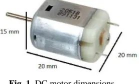
For this project was considered a plant with a feature of 9V DC motor, which was coupled with a twin motor working as a generator and was used as a sensor for the system feedback process, and allowed detecting the state of the motor any time required. In nominal conditions and without vibrations with a good coupling the current consumption was 0.2 A. Physical dimensions of the motor are shown in the Fig. 1.
Fig. 1. DC motor dimensions.
It worth to mention that the work in the laboratory was not in nominal conditions because the inertia of the motor-generator system could break with a voltage of 8 V. With that voltage was possible to generate up to 3.8 V of response for a square pulse train which was put through it. The reasons to generate less voltage than the applied into the motor were frictional losses, vibrations, electric and magnetics circuit’s losses, among others, so that even taking a perfect coupling, it could only generate up to 4.5 V with the motor and the generator working at nominal values. Another reason to work at lower voltage levels than the nominal value was to increase the useful life of the engines.
As a result, a PWM signal was provided with a frequency of 100 Hz and an amplitude of 8 V to the plant. The sensor generated a voltage of 3.9 V.
B. Mechanical Coupling
It was necessary to run correctly the automatic control, in order to guarantee the sensor used return correct data. For this case, because there were two motors coupled, it generated vibrations that corrupted the information read by the acquisition stage. To improve the physical component was needed to deploy a structure that removes misalignment of the axes. Clamps were used to set the two motors to the metallic base. The dimension of the threaded rods used was 5/32 inch. The metallic base to hold the motor-generator system was a base metal carbon steel with 8 mm thick. Additional features were considered: the motors were covered in support areas with brackets made of anti-vibration sponge and clamps, plus screws were placed with pressure
[image:2.595.334.518.118.242.2]rings. A whole metal-plate motor on the bottom surface in contact with the workstation system, plus an antistatic sponge were added, in order to avoid the presence of eddy currents, which could lead to erroneous data. The result of the final physical system is shown in Fig. 2.
Fig. 2. Mechanical coupled system.
C. Modeling Plant
To model the plant, MATLAB’s Ident tool is used [1][2]. Data acquisition through the identification is made with a DE0 Nano board [10] with FPGA [5].
First, the signal is filtered to obtain only the parts that are deemed necessary, in this case signals ranging from 2.7 to 3.8 volts approximately, which are the responses when the system is powered by a PWM signal of 60Hz and 100Hz, respectively. With the information acquired and the Ident tool, the transfer function that better approximates the behavior of the plant is obtained. To estimate this, there were used two poles and one zero in the transfer function. Fig. 3 shows the results obtained in MATLAB.
Fig. 3. Transfer function of the plant obtained with MATLAB’s Ident tool.
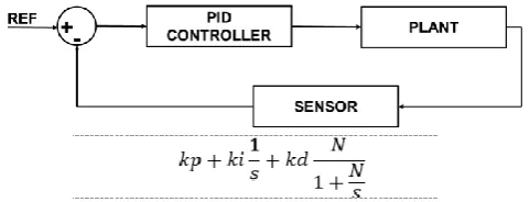
To build the system controller, a classic PID control [1][6] as the ones used in the undergraduate courses of automatic control courses was considered. To evaluate the controller parameters, MATLAB’s PIDTOOL function was used. This evaluates the system and returns the values for the proportionally, integrative and derivative constants that are part of the model and adjust the PID controller for a better performance. Fig. 4 shows the transfer function of the PID controller obtained with MATLAB’s PIDTOOL.
D. Embedded System
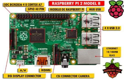
[image:2.595.107.246.338.422.2]world, useful to perform electronics projects. The operating system distributions range that handles this embedded platform is based on the Linux operating system: an open source operating system and for free distribution. There are several distributions available for testing, being the case of Raspbian, the official manufacturer's distribution based on Debian and optimized for Raspberry Pi, which has 35,000 available packages and pre-compiled for easy installation. Wolfram Alpha has also preinstalled, which is also a mathematical modeling tool, which for a moment was considered to be used, but was dropped because additional packages have to be paid. Raspberry Pi 2 B+ has an ARM Cortex-A7 900MHz quad-core, and has a RAM of 1GB. The board has four USB 2.0 ports, 40 GPIO pins, a video output port Full HDMI, an Ethernet port, a combined audio port and composite video as shown in Fig. 5 [7]. For data storage an SD card is used, having there the operating system.
[image:3.595.312.550.85.194.2]Fig. 4. Transfer Function for the PID controller obtained with MATLAB’s PIDTOOL.
Fig. 5. Distribution of ports on Raspberry Pi 2 Model B+.
The board has 40 pins freely accessible to the user, 26 of them are pins for general purpose or GPIO, useful for UART and SPI communication. It has also pins that deliver voltages of 3.3 V and 5 V with their respective ground pins. This pin map is based on the BCM2835 distribution specified in Fig. 6. It is necessary to say that pins from Raspberry Pi have not internal protection and is recommended connect no more than 3.3 V, although the same board can energize up to 5 V.
It is needed the use of an external ADC due to the lack of an ADC module into the board, in order to abstract the analog data that may be required during the control, not only in the case of a specific plant, but also to any other use of the embedded system for development purposes. It can be used several programming languages with libraries, such as Python, C ++, C, Basic, Java, among others, to use the general purpose pins that interacts directly with the external environment. The chosen ones were Python and C ++, due to reasons inherent to their management and interaction with
Octave, which requires at the same time interaction with the GPIO pins to interact with the plant and the sensor.
Fig. 6. BCM2835 distribution in Raspberry PI 2 B + GPIO.
E. Signal conditioning
Another important issue is the mechanical connection between the plant and the sensor. It is also necessary the conditioning of the input and output signals to both the controller system and the controlled system, in order they can communicate by the same parameters. Knowing the variables of the plant and the sensor, the sensor must return a signal voltage, which is a function of the speed regarding to the plant. This voltage for the Raspberry must be connected to its external ADC, ADS115. This analog signal is filtered by a 100uF capacitor to stabilize the data that enters to the ADC to also reduce the noise. Due to the low frequencies handled within the ADC and the sensor, a low pass filter is enough to obtain a good signal reliability. Although the ADC supports an input of 5.5 V, it has been placed protection diodes to the ADC input and generator output to isolate the embedded system circuit to avoid unexpected increases in current or voltage surges, as this was unprotected. The circuit is shown in Fig. 7.
Fig. 7. Signal conditioning between the sensor and the ADC. This is also applicable to the connection between the ADC and the sensor, since the model is feedback controlled. The signal sent is a PWM, which is conveyed through one of the Raspberry Pi’s pins to a transistor that acts as a switch and amplifier. When this signal is applied and closes the circuit, the current flows through the plant and if the voltage is enough to break the inertia of the system, the motor starts to move. As in the case of the sensor, for Raspberry Pi protection a diode was placed to prevent an overcurrent (Fig. 8).
F. Software
[image:3.595.60.275.419.558.2] [image:3.595.306.548.455.555.2]the use of a "batch-oriented" programming, aimed to carry out tasks without the user interaction. In order to execute each of the instructions send a group of input data processed in a group that is a "batch processing", thus returning a group of output data. For processes data must be collected in a group or be stored in a set by this way, processing Octave like a unit.
Fig.8. Signal conditioning between GPIO and the plant It is necessary to show that is possible to create scripts using Octave through languages that can extend its properties, e.g., Python, C ++, C, FORTRAN, among others. On the other hand, Octave is free software, being distributed and modified according to the needs, always under the GNU General Public License (GPL) and also published by the Free Software Foundation.
The next step was to install and test the control toolbox in the Octave environment. Own repositories for Octave were used. It can be installed a toolbox just writing the command "-forge pkg install package_name". It was installed from the Linux console using the "apt-get install octave-control" command and the 2.3.52 package as the compatible version with the Octave version installed. Sometimes, even though the control toolbox is installed, this is not initialized in Octave; in this case, it just loads the toolbox in the environment with the "load pkg-name" command to be executed in Octave [9].
III. TEST AND RESULTS
A. Results for the PID Test
Based on a classic PID control model as shown in Fig. 9 and using the Octave API in C ++, it is possible to make the control of the proposed plant. To measure and display the results was used the Analog Discovery Oscilloscope from Digilent.
Fig.9. Model of the proposed system.
[image:4.595.46.291.135.292.2]The reference was set to 3 V on the sensor output. The stabilization takes about 20 seconds, which for the case of study is not bad for the platform used (Fig. 10).
Fig. 10. Response taken with a fixed reference.
When a variable reference is added, the controller does not stabilize the plant with the same easiness as it does when the reference remains fixed (Fig. 11). As point to point is analyzed, it is noticed that the change from the reference level keeps an error in the tenth between 4% and 7%, and it represents a big mistake for a motor dimensions chosen, because the delivered values are in a range between 2.5 to 3.8 volts as was mentioned before.
Fig. 11. Results of the experiment 2 with PID. Variable reference.
B. Results for Software Test
[image:4.595.308.542.409.582.2] [image:4.595.48.289.659.751.2]TABLE I
RUNTIMES PID CONTROLLER IN SECONDS
Test Initializa tion
Sum of Iterations
Average iteration
Slower
Iteration Total time P1 0.5726 292.06 0.2434 0.4363 292.6326 P2 0.5712 291.75 0.2431 0.4333 292.3212 P3 0.523 291.92 0.2433 0.4360 292.4430 P4 0.5671 291.68 0.24307 0.43506 292.2471
Aver
age 0.5585 291.8525 0.2432 0.4352 292.4110
Fig. 12 depicts a time histogram for one test. In the PID are 1,200 iterations and the highest concentrations are in the inner loop iterations, which is around 0.24 seconds. This time could be less, but it was necessary to add a delay in the program, because the plant did not respond to the same speed as the controller.
[image:5.595.46.295.60.166.2]Fig. 12. Percentage of iterations for PID Controller.
C. Results for Hardware Test
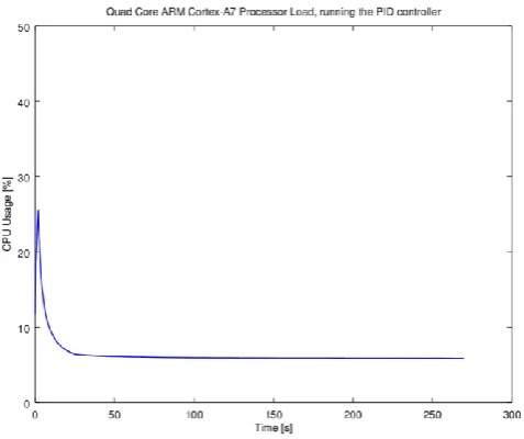
[image:5.595.48.289.251.380.2]The Quad Core ARM processor in the Raspberry has a consumption of 12% without performing the PID execution (Fig. 13). Likewise, when the program starts to instantiate PID, the peripherals have a useful charge of 26%. Then, charge decreases as control iterations start, e.g., the acquisition and adjustment of the PWM controller output.
Fig. 13. Percentage of CPU usage while the Raspberry executes PID control.
IV. CONCLUSION
The initial hypothesis was tested, assuming a controller run on an embedded open source platform using system mathematical models, such as is posed in undergraduate courses.
Communication libraries were tested with embedded system environment that allows abstracting the use of general-purpose pins. A library in Python and another in C ++ were evaluated. It was verified that interaction between Python and Octave with the Oct2Py library was useful only to analyze groups event, but did not provide reliability to generate continuous control event by event, as the C ++ library did.
ACKNOWLEDGMENT
The authors would like to thank Vladimir Sanchez Padilla, because of his review and advice in the technical literature of the present paper.
V. REFERENCES
[1] Dukkipati, R. V. (2013). Matlab for Control System Engineers. New Academic Science.
[2] Keesman, K. J. (2011). System Identification: An Introduction. Springer.
[3] Love, R. (2010). Linux Kernel Development, Third Edition. Pearson Education Inc.
[4] Marsh, N. (2010). Introduction to the Command Line. The Fat-Free Guide to Unix and Linux Commands. Second Edition.
[5] Moore, A. (2014). FPGAs for Dummies, Altera Special Edition. Hoboken: John Wiley & Sons, Inc.
[6] Moudgalya, K. (2008). Digital Control. Wiley-Interscience. [7] Norris, D. (2014). Raspberry Pi Projects for the Evil Genius.
McGraw-Hill Education.
[8] Pérez Adrover, E. (2012). Introduction to PLCs: A beginner's guide to Programmable Logic Controllers. Elvin Perez Adrover.
[9] Schmidt Hansen, J. (2011). GNU Octave. Beginner's Guide. Birmingham: Packt Publishing.
[image:5.595.49.288.511.711.2]