Reinforced concrete (RC) deep beams are structural members characterized by relatively small shear span to depth (a/d) ratios. Sectional analysis as well as design procedures are not valid for these members due to the complex interaction of flexure and shear. The strut-and-tie method (STM) has been widely accepted and used as a rational approach for the design of such disturbed regions (D regions) of reinforced concrete members, where traditional flexure theory cannot be used. The flow of stress is idealized as a truss consisting of compressive struts (concrete) and tension ties (reinforcing steel) transmitting the loads to the supports. Usually, STM considers only equilibrium. Hence, there is no unique solution for a given system, as one can find more than a single truss geometry admissible for a given force field. Therefore, the model which gives the maximum capacity can be considered as the most appropriate one. This paper attempts to predict the ultimate strength of deep beams failing in diagonal compression as well as tension, from the experimental database available in literature based on STM. A modified approach has been used, considering the crushing and splitting failures of the diagonal strut separately. Crushing failure of the diagonal strut has been predicted using a plastic Strut-and-tie model with varying compression zone depth. A localized STM has been considered to predict the splitting failure of the diagonal strut.
Index Terms— Crushing, Deep beams, Disturbed, Splitting, Strut and tie
I. INTRODUCTION
einforced concrete deep beams find wide applications as transfer members in high rise buildings. These are characterized with shear span to depth ratios less than 2, making the behaviour shear dominated. According to St. Venant's principle, also supported by an elastic stress analysis, the localized effect of a concentrated load or geometric discontinuity will attenuate about one member depth away from the discontinuity. These regions, known as 'D' regions (‘D’ stands for discontinuity/disturbed) are assumed to extend one member depth from the loading point or geometric discontinuity. Therefore, the entire region of a deep beam can be considered to be disturbed.
Schlaich (1987) developed the Strut-and-tie method (STM) to primarily design ‘D’ (discontinuity or disturbed) regions, where the strain distribution is nonlinear. STM is a
Manuscript received Dec 15, 2016; revised Jan 16, 2017.
1Research scholar, Indian Institute of Technology, Madras,
(Tel: +91-967 718 2062, email: [email protected])
2Research scholar, Indian Institute of Technology, Madras,
(email: [email protected])
3Professor, Indian Institute of Technology, Madras,
(email: [email protected])
4Professor, Indian Institute of Technology, Madras,
(email: [email protected])
versatile tool for the analysis of these regions, where sectional analysis and design procedures are not valid. It is an intuitively rational method which considers actual flow of forces with in the member.
Strut-and-Tie method is based on the lower bound theorem of plasticity which states that any statically admissible stress field that is in equilibrium with the applied forces and in which stress levels are within the material yield surface constitutes a lower bound solution. Therefore, the capacity obtained from a strut-and-tie model is always less than the actual capacity.
The work presented in this paper is a modification to the existing Strut-and-tie methods, aimed at predicting the crushing as well as splitting failures of diagonal strut for reinforced concrete deep beams. A simple equilibrium based plastic STM is used to predict the crushing failure of the diagonal strut. A localized STM for diagonal strut is used to predict the splitting failure. This paper compares the equilibrium based plastic STM (considering splitting, with the proposed parameters) and conventional elastic STM for strength prediction of deep beams using the results from experiments conducted by Clark, A.P. (1951), Mathey, R.G., and Waststein, D. (1963), Yang, K.H., Chung, H.S., Lee, E.T., and Eun, H.C (2003), Birrcher et.al. (2009), and Ray Kai Leung Su and Daniel Ting Wee Looi (2016).
II. STRUTANDTIEMETHOD
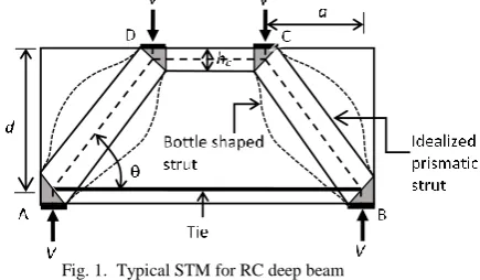
Strut-and-tie method idealizes the force flow with in the member as a hypothetical truss consisting of compression struts and tension ties joined together at regions referred to as nodes. Struts, ties and nodes are proportioned to resist the externally applied forces. Fig. 1 shows a typical Strut-and-Tie model for a reinforced concrete beam subject to symmetric two point loading.
It is preferable to use a determinate truss models over indeterminate models so that equilibrium conditions are sufficient to determine the forces on struts and ties. However, there is always more than one truss geometry which is in equilibrium with the external loads. Therefore it is important to choose the right model for strength
Assessment of Strut-and-Tie Methods to
Estimate Ultimate Strength of RC Deep Beams
Adrija D
1, Indu Geevar
2, Devdas Menon
3, A Meher Prasad
4 [image:1.595.327.545.577.704.2]R
prediction. Since the strut-and-tie method is based on lower bound theorem of plasticity, the truss geometry which gives the maximum capacity is selected.
Struts can be classified as ‘prismatic’ ‘bottle shaped’, or ‘fan shaped’, based on the shape of the stress trajectories in the strut. Prismatic struts are assumed to have uniform cross-sections throughout (Strut CD in Figure 1). Bottle shaped struts take the shape of a bottle and have lateral spread due to orthogonal tension. Crack control reinforcement is required to take care of the tension. For analysis and design purposes, bottle shaped struts are generally idealized as prismatic.
Nodes are the intersection areas of strut and tie in a STM which is similar to joints in trusses. These are highly stressed regions of a structural member and hence it is necessary to check the stresses at the face of the node. For equilibrium, at least three forces are required to act at a node. Based on the number of ties anchored, nodes are generally classified as CCC, CCT, and CTT. As the names suggest, CCC nodes have compressive forces acting on all the three faces, CCT nodes have one tie anchored and CTT node has more than one tie anchored. Limiting stresses at struts and nodes are specified by codes based on the strut and node type respectively. For the present study, a modified equilibrium based strut and tie model (determinate truss model) for deep beams has been considered. This model is capable of predicting all possible failure modes in the member. The codal recommendations from ACI 318-14 has been followed as given in section III.
III. ACI318-14RECOMMENDATIONS
ACI code recommends the design of struts, ties and nodes based on the following criteria.
ns us
F F
. 1
nn un
F F
. 2
nt ut
F F
. 3
where Fns, Fnn and Fntrepresent the nominal strength of strut, face of node, and tie respectively (Table I and Equation 4).
Fus, Fun and Fut are the factored force on the strut,face of the node and tie respectively. Ф is the strength reduction factor which is taken as 0.75. For comparison with experimental specimens in the present study, the strength reduction factor, Φ is not considered.
Strength of struts Strength of nodes
Fns = fceAcs Fnn = fceAnz
fce= 0.85βsfc’ fce= 0.85βnfc’
Acs = Cross sectional area of the strut.
βs = 1.0 (prismatic struts)
= 0.75 (bottle shaped with crack control reinforcement as per Eq.5)
= 0.6 (bottle shaped without crack control reinforcement as per Eq 5)
Ans = Area of the face of the
nodal zone
fc’= cylinder compressive
strength of concrete βn=1.0 (CCC node)
= 0.8 (CCT node) = 0.6 (CTT node)
where fy and Ast are yield strength and area of tie reinforcement respectively. Crack control reinforcement as per ACI 318-14 should satisfy the following criteria.
sin 0.003
sii i
A
bs . 5
where Asiis the total area of surface reinforcement at spacing
siin the ith layer of reinforcement crossing a strut at an angle αi to the axis of the strut
IV. EQUILIBRIUMBASEDSTMFORDEEPBEAMS
It has been observed that a single panel STM which assumes direct transfer of loads to supports is the dominant mechanism for beams with a/d ratios less than 2. (Birrcher et.al., 2009). Therefore the model shown in Fig.1 is chosen for the present study. The component forces in the STM can be calculated as:
tan
AB
V
F (tension) . 6
tan
CD
V
F (compression) . 7
sin
AD BC
V
F F (compression) . 8
where θ is inclination of diagonal struts (AD & BC) with the horizontal.
The STM can be developed based on elastic (Elastic STM) as well as plastic (Plastic STM) theories. The former is developed based on the elastic trajectories. However the solution obtained from such a model may be highly conservative. Plastic STM is based on the truss geometry at ultimate limit state. However, Schlaich (1987) recommends the deviation of the developed STM not greater than 15 degrees from the elastic STM.
A.ELASTICSTM
In this model, the vertical positions of nodes C and D are fixed based on elastic analysis assuming linear strain and stress distribution. Therefore, the height of the compression zone (with uniform stress), hc,e is given by,
, 2 3
c e
kd
h . 9
where
2
2
kd
m
m
m d
. 10Here, kd is the depth of neutral axis from the extreme compression fibre, ρ is the tie reinforcement ratio (= Ast/bd) and m is the modular ratio (=Es/Ec where Es and Ec are the moduli of elasticity of steel and concrete respectively). Es is taken as 200000 MPa and Ec is determined as 5000 fck
where fck = 1.25fc’.
The tie, strut and nodal strengths are directly based on ACI codal recommendations. The failure load is determined based on the minimum of tie strength, node strength and strut strength. However this model is found to give highly conservative values of collapse load.
B.PLASTICSTM
TABLE I
observed to exhibit two types of failure modes namely diagonal crushing and diagonal splitting. Two different strut and tie models are considered to predict these modes separately. The collapse load is determined as the minimum of the loads obtained from these models.
B.1 RESISTANCE AGAINST CRUSHING
Crushing strength of the diagonal strut is computed based on the ACI recommendations, considering a plastic strut-and-tie model. The height of the compression zone is considered as a variable to obtain the optimum truss configuration which gives the maximum capacity. The effect of CCT node width on diagonal strut size has been ignored as per the studies conducted by Birrcher et.al. It is also proposed to consider the enhancement in area at top face of nodes C and D to consider the spread of forces. The diagonal strut width is computed based on ACI recommendations as shown in Fig.2.
hc can be evaluated as the maximum width required to avoid the crushing failure of struts as well as nodes (C & D).
,lim sin
max , cos 0.85 '
s b CD
c
c
w l F
h
f b
. 11
where ,lim
0.85 '
BC s
s c
F w
f b
. 12
Once the node positions are fixed, the diagonal strut inclination, θ can be evaluated as,
1 2
tan
c
h d
a
13
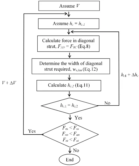
This is achieved using a simple iterative procedure in MATLAB. The diagonal strut is assumed to be prismatic (βs = 1), since the splitting failure of the strut is considered
separately. It is important to note that, for over-reinforced beams, ties do not reach their capacity. Fig.3 shows the solution algorithm followed. The ultimate load is estimated as the load at which either the tie reinforcement yields (under-reinforced) or the height of the compression zone (based on Eq.11) reaches its maximum limit possible (over-reinforced).
B.2 RESISTANCE AGAINST SPLITTING
Splitting failure of deep beams is characterized by wide opening of diagonal cracks due to the orthogonal tension in the diagonal struts. In the original model recommended by ACI, the reduction in strut strength due to diagonal tension is taken into effect by considering a reduced value of strut efficiency factor βs, which depends on the amount of crack
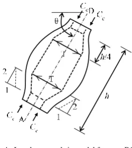
control reinforcement provided. However, a local strut-and – tie model can be used to predict the resistance of diagonal strut against splitting failure. In the present study, a strut and tie model (EN 1992-1-1) as shown in Fig.4 is used to evaluate the splitting strength of the diagonal strut.
[image:3.595.317.553.55.337.2]Once the tie in the local strut-and-tie model yields, equilibrium of the model cannot be maintained. Therefore, the resistance of the beam against diagonal splitting can be evaluated as a function of the tensile capacity T of the local STM. In the case of reinforced concrete deep beams without web reinforcement, the direct tensile strength of the concrete determines the capacity of the tie in the local STM. The local tie is assumed to yield once it reaches the splitting tensile strength of concrete. In the case of reinforced concrete deep beams with sufficient web reinforcement, the component of the web reinforcement orthogonal to the diagonal strut is assumed to provide the splitting resistance. The yielding of local tie occurs when the web reinforcement crossing the strut yields.
Fig. 3. Solution algorithm for crushing failure
[image:3.595.54.230.299.459.2]From the strut geometry, the tensile force on the tie, T can be evaluated as:
2
C
cT
14For the truss geometry as shown in Fig.1, force, Cc can be determined as:
2Sin
c
V
C 15
Substituting this in Eq.14, the strength of the deep beam against splitting failure, VT can be calculated as
4 sin
T
V T . 16
For deep beams without web reinforcement, tensile capacity
T is obtained as:
ct cs
T f A . 17
Where fct is the splitting tensile strength of the concrete. The area of the diagonal strut (Acs) is given by:
,max
cs s
A w b 18
where ws,max is width of the diagonal strut at maximum spread.
For deep beams with web reinforcement, the maximum tensile capacity T orthogonal to the diagonal strut is the function of areas of horizontal and vertical web reinforcements (Ash and Asv). Therefore T is estimated as
cos sin
yv sv yh sh
T f A f A . 19
where fyv and fyh are the yield strengths of vertical and horizontal web reinforcements respectively. The tensile contribution of concrete is negligible compared to that of reinforcement and hence can be neglected. To estimate θ, height of the compression zone of the model has been fixed as per elastic analysis assuming linear strain and stress distribution.
V. CONCLUSION
From the comparative study the following conclusions are drawn:
Elastic STM which considers the determinate
strut-and-conservative. Although it is the simplest method, it is not recommended for practical design.
Plastic STM with the proposed parameters could predict the failure load with about much less conservatism. The variation with in the results were also found to be less as compared to elastic STM.References
[1] ACI 318-14. 2014 Building Code Requirements for
Structural Concrete and Commentary, American
Concrete Institute, Farmington Hills, MI.
[2] Birrcher, D. B.; Tuchscherer, R. G.; Huizinga, M. R.; Bayrak, O.; Wood, S. L.; and Jirsa, J. O., “Strength and Serviceability Design of Reinforced Concrete Deep Beams,” Report No. 0-5253-1, Center for Transportation Research, the University of Texas at Austin, Austin, TX, Apr. 2009.
[3] Clark, A. P., “Diagonal Tension in Reinforced Concrete Beams,” ACI Journal, V. 48, No. 10, 1951, pp. 145 –
156.
[4] EN 1992-1-1: Eurocode 2: Design of concrete structures – Part 1-1: General rules and rules for buildings, European committee for standardization, Brussels, Belgium; 2004.
[5] Examples for the design of structural concrete with Strut-and-Tie Models, ACI SP 208, Karl-Heinz Reineck , Farmington Hills, Mich.: American Concrete Institute; 2002.
[6] Mathey, R.G., and Watstein, D., “Shear Strength of Beams without web reinforcement containing deformed bars of different yield strengths” ACI JOURNAL,
proceedings V.60, No.2, pp 183-208, Feb 1963, [7] Schäfer, K., “Strut-and-Tie Models for the Design of
Structural Concrete”, Notes from Workshop,
Department of Civil Engineering, National Cheng Kung University, Tainan, Taiwan, 140 pp. 1996.
[8] Schlaich, J., Kurt Schäfer, and Mattias Jennewein. “Toward a Consistant Design of Structural Concrete.”
PCI Journal. V. 32, No. 3, 1987, pp. 74-150, 1987. [9] Su, Ray Kai Leung; Looi, Daniel Ting Wee, “Revisiting
Unreinforced Strut Efficiency Factor”, ACI Journal, V.
113, No. 2, pp. 301 – 315, March-April 2016.
[10]Yang, K. H., Chung, H. S., Lee, E. T., and Eun, H. C., “Shear characteristics of high-strength concrete deep beams without shear reinforcements,” Engineering
[image:4.595.94.227.66.216.2]Structures, Vol. 25, pp. 1343-1352, 2003.
Author Specimen a/d f'c MPa
fy
MPa Ast
mm2 Asv mm2 Ashmm2 VTEST
kN
STM, ELASTIC
STM, PLASTIC
TEST
STM
V V
TEST
STM
V V
Mathey, R.G., and Waststein,
D.
I-1 1.51 25.40 267 2495 0 0 310 1.85 1.61
I-2 1.51 23.00 267 2495 0 0 305 1.99 1.69
II-3 1.51 21.90 465 1538 0 0 259 1.92 1.68
II-4 1.51 26.40 465 1538 0 0 309 1.93 1.49
III-5 1.51 25.70 489 1513 0 0 285 1.84 1.48
III-6 1.51 25.60 489 1513 0 0 285 1.84 1.47
IV-7 1.51 24.20 446 1522 0 0 285 1.94 1.50
IV-8 1.51 24.90 446 1522 0 0 298 1.97 1.58
V-9 1.51 23.10 694 949 0 0 222 1.71 1.27
V-10 1.51 27.00 694 949 0 0 267 1.78 1.32
VI-11 1.51 25.10 694 957 0 0 222 1.58 1.24
VI-12 1.51 25.70 694 957 0 0 268 1.87 1.39
V-13 1.51 22.40 711 614 0 0 220 1.89 1.30
V-14 1.51 26.70 711 614 0 0 221 1.61 0.88
VI-15 1.51 25.50 711 614 0 0 178 1.35 1.01
VI-16 1.51 22.80 711 614 0 0 186 1.57 1.04
Clark, A.P.
D0-1 1.16 25.86 370 784 0 0 223 1.29 0.97
D0-2 1.16 26.20 370 784 0 0 262 1.50 1.14
D0-3 1.16 25.96 370 784 0 0 225 1.30 0.98
C0-1 1.55 24.68 370 784 0 0 176 1.37 1.03
C0-2 1.55 23.48 370 784 0 0 179 1.45 1.05
C0-3 1.55 23.58 370 784 0 0 168 1.36 0.99
B0-1 1.94 23.58 370 784 0 0 122 1.23 0.89
B0-2 1.94 23.91 370 784 0 0 95 0.95 0.72
B0-3 1.94 23.51 370 784 0 0 129 1.30 0.95
Yang,K.H., Chung,H.S.,Le
e,E.T., and Eun,H.C
L5-40 0.56 31.40 804 568 0 0 447 1.80 1.59
L5-60 0.54 31.40 804 870 0 0 535 1.88 1.80
L5-75 0.55 31.40 804 1096 0 0 597 1.95 1.89
L5-100 0.53 31.40 606 1346 0 0 582 1.73 1.89
L10-40R 1.13 31.40 804 568 0 0 312 1.86 1.22
L10-60 1.08 31.40 804 870 0 0 376 1.78 1.45
L10-75R 1.09 31.40 804 1096 0 0 330 1.40 1.27
L10-100 1.07 31.40 606 1346 0 0 545 2.02 2.03
UH5-40 0.56 78.50 804 568 0 0 733 1.23 0.96
UH5-60 0.54 78.50 804 870 0 0 823 1.22 1.11
UH5-75 0.55 78.50 804 1096 0 0 1011 1.40 1.77
UH5-100 0.53 78.50 606 1346 0 0 1029 1.29 1.37
UH10-40 1.13 78.50 804 568 0 0 499 1.35 1.31
UH10-60 1.08 78.50 804 870 0 0 574 1.17 0.94
UH10-75R 1.09 78.50 804 1096 0 0 361 0.66 1.06
UH10-100 1.07 78.50 606 1346 0 0 769 1.21 1.05
TABLE II
Author Specimen a/d f'c MPa
fy
MPa Ast
mm2 Asv mm2 Ashmm2
VTEST
kN
STM, ELASTIC
STM, PLASTIC
TEST
STM
V
V
TEST
STM
V
V
Su, Ray Kai Leung and Looi, Daniel
Ting Wee
C30-1.7 1.59 27.60 289 378 0 0 137 2.23 2.12
C60-1.7 1.59 53.90 592 646 0 0 295 1.85 1.38
C90-1.7 1.59 78.30 592 971 0 0 377 1.58 1.17
C30-1.0 0.80 28.20 602 540 0 0 341 1.99 1.41
C60-1.0 0.80 55.00 592 964 0 0 652 1.91 1.38
C90-1.0 0.80 85.20 587 1144 0 0 854 1.62 1.16
C30-0.5 0.45 27.40 602 540 0 0 322 1.41 1.12
C60-0.5 0.43 54.40 592 667 0 0 700 1.53 1.19
C90-0.5 0.45 81.10 592 964 0 0 947 1.39 0.93
C60-0.5 0.43 54.40 592 667 0 0 700 1.53 1.19
C90-0.5 0.45 81.10 592 964 0 0 947 1.39 0.93
Birrcher et.al.
I-03-2 1.84 36.13 503 11945 2783 1645 2531 1.16 0.99
I-03-4 1.84 36.75 503 11945 2879 1645 2922 1.31 1.11
I-02-2 1.84 27.23 503 11945 1920 997 2019 1.53 1.18
I-02-4 1.84 28.68 503 11945 2016 997 2348 1.63 1.23
II-03-CCC2021 1.84 22.68 441 12081 2983 2249 2224 2.44 1.28
II-03-CCC1007 1.84 23.99 441 12081 2983 2249 2126 3.20 1.83
II-02-CCC1007 1.84 21.65 476 12081 1925 950 1490 2.49 1.40
II-02-CCC1021 1.84 31.85 476 12081 1925 950 1463 1.40 0.93
II-03-CCT1021 1.84 30.41 455 12081 2983 2249 2829 2.32 1.27
II-03-CCT0507 1.84 29.03 455 12081 2983 2249 2660 5.98 1.23
II-02-CCT0507 1.84 21.51 476 12081 1925 950 1784 5.43 1.11
II-02-CCT0521 1.84 32.68 476 12081 1925 950 2527 2.95 1.50
III-1.85-00 1.84 21.86 455 12081 0 0 1624 1.85 0.98
III-1.85-02 1.84 28.27 476 12081 1925 950 2171 1.91 1.35
III-1.85-025 1.84 28.27 476 12081 2309 700 2295 2.02 1.25
III-1.85-03 1.84 34.40 476 12081 2791 1449 1833 1.09 0.77
III-1.85-01 1.84 34.54 476 12081 962 700 1214 0.87 1.34
III-1.85-03b 1.84 22.75 476 12081 2983 1449 2095 1.89 1.20
III-1.85-02b 1.84 22.75 476 12081 1925 950 2082 2.27 1.33
III-1.2-02 1.2 28.27 455 12081 1255 994 3763 2.12 1.77
III-1.2-03 1.2 29.10 455 12081 1945 1517 3688 1.66 1.36
IV-2175-1.85-02 1.85 33.99 469 22124 3627 1711 3394 1.78 1.09
IV-2175-1.85-03 1.85 33.99 469 22124 5354 2612 3745 1.60 0.85
IV-2175-1.2-02 1.2 34.54 469 22124 2352 1711 4995 1.75 1.65
IV-2123-1.85-03 1.85 28.68 455 6129 1466 732 1463 1.21 1.35
IV-2123-1.85-02 1.85 29.10 455 6129 978 415 1544 1.47 1.53
M-03-4-CCC2436 1.85 28.27 462 27221 5328 2401 5018 1.41 1.22
M-03-4-CCC0812 1.85 20.68 448 27221 5328 2401 4137 5.36 2.92
M-09-4-CCC2436 1.85 28.27 462 27221 14781 2401 6294 1.76 1.51
M-02-4-CCC2436 1.85 19.31 448 27221 3781 1957 4902 2.40 1.67
M-03-2-CCC2436 1.85 33.78 469 27221 5328 2401 4875 1.14 1.16
Avg 1.82 1.28