Comparative Analysis of Methods to
Reduce Blocking Artifacts in Images
and Videos
Ekta Patel
P.G. Student, Department of Computer science & Engineering, Bhabha Engineering research institute, Bhopal, MP, India1
Prof.(Dr.)Mohit Gangwar
Principal ,Bhabha Engineering Research Institute, Bhopal, MP,India
Abstract :
The demand for communication with moving video picture is increasing rapidly. Video and image compression is the wide spread field in communication engineering and computer science. It is useful for illustration of video data, for storage and/or transmission. Block based motion estimation and motion compensation method is widely used in most of video coding standards including H.264/AVC to compress raw video. There is a loss of accuracy of block coefficients during transform coding and quantization process. It will result in visually disturbing discontinuities at the block boundaries of reconstructed frame which reduce visual quality. Discontinuities at block boundaries are known as Blocking Artifacts. In order to remove blocking artifacts and improve the quality of the reconstructed video, several de-blocking algorithms have been proposed.
.
Keywords: Block Based Motion estimation, H.264/Avc, Deblocking Algorithms, Offset-shift Algorithm, Novel Algorithm, Directional de-blocking Algorithm, Average de-blocking Algorithm.
1. Introduction
Video compression is important topics of research in the field of multimedia. As raw videos are large in size without compress video it is difficult to transmit videos over a network or store them on a storage media. The amount of information contained in a raw video can be calculated by considering its height (H), width (W), number of channels, colour depth and sequence length Data rate required for 30 Frames per Second. full HD High Definition color video is 30×1920 1088 3 8 = 1.5 Gbps, which is impractical for today’s
communication or storage infrastructure [1]. Such high data rate indicates the requirement of video encoding standard and hence several video coding standards have been developed for compression of raw video. such as H.264/AVC encoding Standard. Most of the video coding standards including H.264 use block based Motion Estimation and Motion Compensation technique for raw video compression.MC blocks are further transform coded and quantized to achieve high compression. But quantization of the transform coefficients and motion compensation of block can cause visually disturbing discontinuities at the block boundaries and reduce visual quality of decoded videos. Here discontinuities at the block boundaries are known as Blocking Artifacts [2]. De-blocking filter is necessary to remove these De-blocking artifacts produced during decoding process.
2. Problem Definition
De-blocking filter helps in improving the subjective and objective quality of the output frames, but it is generally computationally intensive. De-blocking filter can easily account for one-third of the computational complexity of a decoder. This complexity is mainly based on the high adaptivity of the filter, which requires conditional processing on the block edge [3]. Hence main problem is to implement less complex de-blocking algorithm for decoder which remove blocking artifacts form frames and increase video quality.
3. Literature Review
There are two main approaches to integrate de-blocking filters into video codec. De-blocking filters can be used either as post filters or loop filters [3]. H.264/AVC de-blocking filter [3] is in-loop filter which apply 1-D weak filter or strong filter on block boundary using threshold. Post filter only operate on the display buffer outside of the coding loop, so the post-processing requires no modifications of existing standards to get better quality and it is the most practical solution to remove the blocking artifacts. In other words post-filters offer maximum
freedom for decoder implementations. Whereas loop filters operate within the coding loop. That is, the filtered frames are used as reference frames for encoding of subsequent frames. This forces all standard decoders to perform identical filtering in order to stay in synchronization with the encoder and increases the computational complexity [3], [8], [9]. According to [8] and [10], post filtering based de-blocking algorithm is better compared to in-loop filtering based algorithm due to less computational complexity.
Y. L. Lee et al. [11] classify the blocking artifacts in BDCT-coded images into three types as follows: grid noises in the smooth area, staircase noises along the image edges, and corner outliers in the cross points of the four 8 x 8 DCT blocks. Numbers of post filtering based de-blocking algorithm have been proposed to remove above all three kinds of noises. De-blocking filter in [9] first remove high frequency components from frame and then according to block activity it uses smooth filtering mode, non-symmetric filtering mode, boundary adjustment mode and corner outliers removal mode to remove blocking artifacts. Lee et al.’s method [11] applied a 2-D filter to the edge map obtained by sobel operator. However, Lee et al.’s method exhibits poor de-blocking performance in edge or texture areas, since sobel operator often detects de-blocking artifacts as real edges. The filters [12] is applied only to the boundary pixels, which are two pixels straddling the block boundary, and thus do not remove the grid noises. Offset-shift algorithm in [8] is able to remove all three kinds of noises but it uses non adaptive fix threshold T to remove noises. Due to fix threshold this algorithm gives poor improvement in PSNR for other images. Another novel algorithm proposed in [10] is not able to remove above all three kinds of noises as they apply 1-D filter or 2-D filter only in middle boundary pixels of two adjacent 8x8 block of frame for horizontal filtering and vertical filtering. De-blocking filter [13] applied offset-shift technique to remove blocking artifacts but it modified only two pixels on either side of boundary in smooth filter and only one pixel on either side of boundary in complex filter. This filter also proposed corner outliers removal mode. But both filters [9] and [13] were not able to remove grid noise efficiently as both filters were applied only on middle pixels of 8x8 blocks. Adaptive de-blocking filter [14] applies 1-D or 2-D strong or default filter on pixels based on their position in block. But this filter offers more computational complexity with less considerable improvement in frame quality. DEBLOCKING FILTERS
This chapter describes de-blocking filter algorithms as post filter to improve the visual quality of frame. Five algorithms are described, novel algorithm in section A and offset and shift techniques in section B, H.264/AVC deblocking filter in section C.
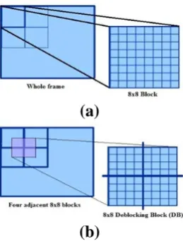
As shown in figure 1(a), first whole frame is divided in 8x8 blocks for all de-blocking algorithms as described above. Then as shown in figure 1(b) 8x8 DB is composed by combining four adjacent 8x8 blocks.
(a)
(b)
Figure 1 (a) 8x8 block in frame (b) 8x8 DB in frame
4. Proposed Methods
Deblocking filters are used to improve the visual quality of frame. Four deblocking algorithm such as novel deblocking algorithm, offset and shift method, Directional deblocking algorithm, Averaging deblocking algorithm are tested on standard images and basedon parameters like PSNR and SSIM the quality of videos and images are tested.
A. Novel De-blocking Algorithm
be divided in mainly four steps, filtering mode decision by finding activity, smooth region filtering, complex region filtering and intermediate filtering.
Start
Divide the whole frame in numbers of 8x8 blocks
Consider 8x8 DBs which are composed from four adjacent 8x8 blocks
Measure activity A(v)of horizontal 1-D array
of pixels in DB at vertical boundary of block
Filter Mode?
Abs(D-C) < 2QP ? Abs(D-C) < QP ?
Smooth
Region Filter Region FilterIntermediate Region FilterComplex
No No
A(v) < T1
Yes
Apply filter to horizontal 1-D array of pixels STEP 1:
STEP 2:
STEP 3:
STEP 4:
STEP 5:
Repeat STEP 3 to STEP 5 for remaining seven horizontal 1-D array of pixels for complete horizontal filtering of DB STEP 6:
Measure activity A(v)of vertical 1-D array of
pixels in DB at horizontal boundary of block STEP 7:
Repeat STEP 4 and apply filter to vertical 1-D array of pixels STEP 8:
Repeat STEP 7 and STEP 8 for remaining seven vertical 1-D array of pixels for complete vertical filtering of DB STEP 9:
End
Repeat STEP 3 to STEP 9 for all DBs in frame STEP 10:
A(v) > T2
Figure 2 Novel deblocking algorithm[10]
Figure 3 Filtering mode decision [10]
As shown in figure 3 A(v) is compared with two thresholds T1 and T2 to determine the appropriate f ltering
mode. T1 is set to a suitable small value to ensure that the region is sufficiently smooth to apply smooth mode
f ltering when A(v) < T1 . Similarly, the use of complex mode f ltering is specif ed if A(v) > T2 in areas of high
spatial complexity. If A(v) is between T1 and T2, intermediate f ltering is used to improve in terms peak
B. Offset-Shift Algorithm
The overall offset and shift algorithm is as shown in figure 4
Start
Divide the whole frame in numbers of 8x8 blocks
Consider 8x8 DBs which are composed from four adjacent 8x8 blocks
Measure horizontal activity (ACTH) and
vertical activity (ACTV) of DB
STEP 1:
STEP 2:
STEP 3:
Calculate adaptive threshold T T1=Average ACTHof all DBs
T2=Average ACTVof all DBs
T= fx (T1, T2)
Where fx ={Average, Maximum, Minimum}
DBs are classified in mainly three types using adaptive threshold T
UDB DDB CDB
VDB
HDB Texture Block BlockEdge
STEP 4:
STEP 5:
STEP 6:
Figure 4 De-blocking block (DB) and pixel positions in DB[8]
(a) (b) Figure 5 Activities of DB (a) Horizontal (b) Vertical [8]
For each DB, Horizontal activity (ACTH) and Vertical Activity (ACTV) are calculated as shown in equation(1)
= =
Δ
=
Δ
=
60 6
0
&
k k V
k
k
H
C
ACT
R
ACT
(1)7 7
, , 1 , 1,
0 0
&
k i k i k k k j k j
i j
C
q
q
+R
q
q
+= =
Δ =
−
Δ =
−
(2)where ΔCk gives the cumulative addition of absolute difference of pixels belonging from kth and
kth+1 column, and ΔR
k gives the cumulative addition of absolute difference of pixels belonging from kth
row and kth+1 row of 8×8 DB as defined in equation (2).After computing activity for all DB its average
Avg_ACTH (Average Horizontal Activity) and Avg_ACTV (Average Vertical Activity) is computed.
Avg_ACTH and Avg_ACTV are considered as T1 and T2 Threshold is different for each frame, and varies
block classification different filtering methods on each DB type are applied as shown in figure 6. Here the shaded pixels are filtered, and length of arrows represents the filtering strength
.
(a) (b)
(c) (d)
Figure 6 Filtering direction and strength for each DB type (a) UDB, (b) HDB, (c) VDB, (d) CDB[8]
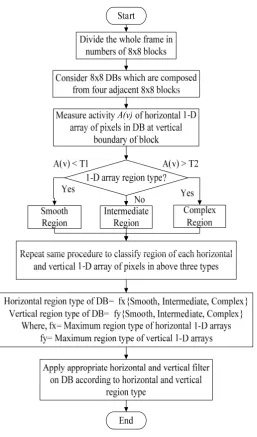
C. Directional Deblocking algorithm
The overall algorithm is as shown in figure 7. As described in figure 8 and figure 9,in this algorithm each horizontal and vertical 1-D array of pixels of whole DB is classified in three region type: smooth region, intermediate region and complex region by finding activity A(v) of each 1-D pixels array.
Start
Divide the whole frame in numbers of 8x8 blocks
Consider 8x8 DBs which are composed from four adjacent 8x8 blocks
Measure activity A(v)of horizontal 1-D array of pixels in DB at vertical
boundary of block
1-D array region type?
Smooth
Region Intermediate Region Complex Region Yes
A(v) < T1
Repeat same procedure to classify region of each horizontal and vertical 1-D array of pixels in above three types
Horizontal region type of DB = fx{Smooth, Intermediate , Complex} Vertical region type of DB = fy{Smooth, Intermediate , Complex}
Where, fx= Maximum region type of horizontal 1-D arrays fy= Maximum region type of vertical 1-D arrays
End
A(v) > T2
Yes No
Classify DB in mainly three types SDB , DDB and CDB based on the horizontal and vertical region type of DB and apply appropriate filter
Figure 8 Activity of all eights 1-D array of pixels of DB in direction (a) Horizontal (b) Vertical
Figure 9 Region type decision in DB
Now the region type which is classified maximum numbers of time during classification of each 1-D array of pixels is considered as the whole region type for DB in horizontal direction and vertical direction as described in figure 9. Thus each DB has two region types, one in horizontal direction and other in vertical
direction. Now each DB is classified in SDB , DDB and CDB based on the horizontal and vertical region type.
CDB further can be classified in texture de-blocking block and edge de-blocking block. DDB further classified in HDB and VDB. After the block classification, different filtering methods on each DB type are applied in same way as was applied in offset and shift de-blocking algorithm.
D. Averaging Deblocking algorithm
This algorithm follows same steps as directional de-blocking algorithm. This algorithm also classified each horizontal and vertical 1-D array of pixels of whole DB in three region type: smooth region, intermediate region and complex region by finding activity A(v) of each 1-D pixels array.
Figure 10 Averaging de-blocking algorithm
Now the region type which is classified maximum numbers of time during classification of each 1-D array of pixels is considered as the whole region type for DB in horizontal direction and vertical direction as described in figure 9. Thus each DB has two region types, one in horizontal direction and other in vertical
direction. As described in figure 10. According to region types filters are applied on DB. For simplicity filter is shown on only one 1-D array of pixels in horizontal direction and in vertical direction. As an example DB may have horizontal smooth filter and vertical complex region.
1) Smooth region filter:
In this region blocking artifacts are removed by applying 3-tap filter with coefficient value {1 2 1} on pixels V2
to V7 in all 1-D array of pixels as described in figure 11(a). This filter is given by equation (3). Where
V
n'represents the filtered pixel and bk is the filter coefficient for the index k from 0 to 2 with the value {1, 2, 1}. In
(3),
V
n denotes the pixel to be filtered.7
2
;
4
1
20 1
'
=
≤
≤
= + −
n
V
b
V
k
k n k
(2) Intermediate region filter:
In this region same 3-tap filter is applied as was applied in smooth region. But as shown in equation (4) this filter modifies only four pixels V3 to V6 only.
6
3
;
4
1
2 0 1 '=
≤
≤
= + −n
V
b
V
k k n k n (4)(3) Complex region filter:
To preserve original details, only two pixels (V4 and V5) are modified with respect to the block boundary using
offset and shift technique as described by equation (5). Here offset represents the amount of adjustment.
(5)
5. Conclusion
Post filter are better compared to in-loop filter because post-processing requires no modifications of existing standards. Only one disadvantage of post filter is that, it requires additional frame buffer to hold filtered frame. Earlier proposed novel algorithm and Offset and shift algorithm are able to remove blocking artifacts efficiently as it apply 1-D filter or 2D filter only in middle boundary pixels of two adjacent 8x8 block of frame for horizontal as well vertical filtering. Offset and shift algorithm uses fixed threshold T to classify DBs in to UDB, HDB, VDB and CDB. So performance of this algorithm may degrade for different standard test images. Here if we can calculate adaptive threshold through Which performance of algorithm can be significantly improved in terms of PSNR (dB) and SSIM for standard test images and video sequences.
REFRENCES
[1] Youn-Long Steve Lin,Chao-Yang Kao, Hung-Chih Kuo, Jian-Wen Chen, “VLSI Design for Video Coding H.264/AVC Encoding from
Standard Specification to Chip”. 1st edition , London, springer, 2010
[2] Jongho Kim and Chun-Bo Sim, “Compression Artifacts Removal by Signal Adaptive Weighted Sum Technique”, IEEE Transactions on
Consumer Electronics, Vol. 57, No. 4, pp. 1944-1952, Nov. 2011.
[3] Peter List, Anthony Joch, Jani Lainema, Gisle Bjøntegaard, and Marta Karczewicz, “Adaptive Deblocking Filter,” IEEE Transactions
on Circuits and Systems for Video Technology, vol.13, no.7, pp. 614-619, Jul. 2003.
[4] ThomasWiegand, Gary J. Sullivan, “Overview of the H.264/AVC Video Coding Standard” IEEE Transactions On Circuits And
Systems For Video Technology, Vol. 13, No. 7, pp. 560-576, Jul. 2003.
[5] Hua-Chang Chung, Zong-Yi Chen, and Pao-Chi Chang, “Low Power Architecture Design and Hardware Implementations of
Deblocking Filter in H.264/AVC”, IEEE Transactions on Consumer Electronics , Vol. 57, No. 2, pp. 713-719, May. 2011.
[6] Tien-Ying Kuo, and Chen-Hung Chan, “Fast Variable Block Size Motion Estimation for H.264 Using Likelihood and Correlation of
Motion Field” IEEE Transactions on Circuits and Systems For Video Technology, Vol. 16, No. 10,pp. 1185-1195, Oct. 2006.
[7] Chen-Kuo Chiang, Wei-Hau Pan, Chiuan Hwang, Shin-Shan Zhuang, and Shang-Hong Lai, “Fast H.264 Encoding Based on
Statistical Learning”, IEEE Transactions on Circuits and Systems For Video Technology, Vol. 21, No. 9, pp. 1304-1315, Sep. 2011.
[8] Jongho Kim, Minseok Choi, and Jechang Jeong, “Reduction of Blocking Artifacts for HDTV using Offset-and-Shift Technique”, IEEE
Transactions on Consumer Electronics, Vol. 53, No. 4, pp. 1736-1743, Nov. 2007.
[9] Jongho Kim and Jechang Jeong, “Adaptive Deblocking Technique for Mobile Video”, IEEE Transactions on Consumer Electronics,
Vol. 53, No. 4, pp. 1694-1702, Nov. 2007.
[10] Shen-Chuan Tai, Yen-Yu Chen, and Shin-Feng Sheu, “Deblocking Filter for Low Bit Rate MPEG-4 Video”, IEEE Transactions On
Circuits And Systems For Video Technology, VOL. 15, NO. 6, pp. 733-741, June 2005.
[11] Y. Lee, H. Kim, and H. Park, “Blocking effect reduction of JPEG images by signal adaptive filtering,” IEEE Trans. Image Process.,
vol. 7, no. 2, pp. 229-234, Feb. 1998.
[12] S. Marsi, R. Castagno, and G. Ramponi, “A simple algorithm for the reduction of blocking artifacts in images and its implementation,”
IEEE Trans. Consumer Electron., vol. 44, no. 3, pp. 1062-1070, Aug. 1998.
[13] Jagroop Singh a, Sukhwinder Singh , Dilbag Singh, Moin Uddin d. (2011) Detection method and filters for blocking effect reduction of
highly compressed images, Journal of ELSEVIER , Signal Processing: Image Communication, 26(2011), pp. 493-506.
[14] M. Anto Bennet and Jacob Raglend. (2012) Analysis of Filtering Schedule Using Deblocking Filter for the Reduction of Block
Artifacts from MPEQ Compressed Document Images, Journal of Computer Science, 8(9), pp. 1447-1454.
[15] [Online].Available:http://decsai.ugr.es/~javier/denoise/test_images/index.htm
[16] Iain E. Richardson, “The H.264 Advanced Video Compression Standard”, 2nd edition, UK, A John Wiley and Sons, Ltd., Publication,
2010.
[18] T. Wiegand, and G. J. Sullivan, “Overview of the H.264/AVC Video Coding Standard” IEEE Trans. on Circuits and Systems for video
technology, vol. 13, no. 7, pp. 560-576, Jul. 2003.
[19] J. Kim and J. Jeong, “Adaptive Deblocking technique for mobile video”, IEEE Trans. on Consumer Electronics, vol. 53, no. 4, pp.
1694-1702, Nov. 2007.
[20] S. C. Tai, Y. Y Chen, and S. F. Sheu, “Deblocking Filter for low bit rate MPEG-4 video”, IEEE Trans. on Circuits and Systems for
video technology, vol. 15, no. 6, pp. 733-741, June 2005.
[21] J.-F. Wang, J.-C. Wang, J.-T. Chen, A.-C. Tsai, and A. Paul, “A novelfast algorithm for intra mode decision in H.264/AVC encoders,”
in Proc.IEEE Int. Symp. Circuits Syst., May 2006, pp. 1–4.
[22] B. Zhan, B. Hou, and R. Sotudeh, “A novel fast inter mode decisionalgorithm based on statistic and adaptive adjustment for
H.264/AVC,”in Proc. 15th Int. Conf. Software, Telecommun. Comput. Netw., 2007,pp. 1–5.
[23] S. D. Kim, J. Yi, H. M. Kim, and J. B. Ra, “A deblocking filter with two separate modes in block-based video coding,” IEEE Trans.
Circuits Syst. Video Technol., vol. 9, pp. 156–160, Feb. 1999.
[24] Draft ITU-T Recommendation and Final Draft International Standardof Joint Video Specification, ITU-T Rec. H.264/ISO/IEC
14496-10AVC, 2003.
[25] T. Wiegand, G. J. Sullivan, G. Bjntegaard, and A. Luthra, “Overviewof the H.264/AVC video coding standard,” IEEE Trans. Circuits
Syst.Video Technol., vol. 13, no. 7, pp. 560–576, Jul. 2003.
[26] Y. K. Tu, J. F. Yang, Y. N. Shen, and M. T. Sun, “Fast variable-sizeblock motion estimation using merging procedure with an adaptivethreshold,” in Proc. IEEE Int. Conf. Multimedia Expo, Jul. 2003, vol.2, pp. 789–792.
[27] C. S. Won, “Variable block size segmentation for image compressionusing stochastic models,” in Proc. IEEE Int. Conf. Image
Process., Sep.1996, vol. 3, pp. 975–978.
[28] A. Zakhor, “Iterative procedures for reduction of blocking effects intransform image coding,” IEEE Trans. Circuits Syst. Video
Technol., vol.2, no. 1, pp. 91-95, Mar. 1992.
[29] Wenfeng Gao, C. Mermer, and Yongmin Kim, “A de-blocking algorithmand a blockiness metric for highly compressed images,” IEEE
Trans.Circuits Syst. Video Technol., vol. 12, no. 12, pp. 1150-1159, Dec. 2002.
[30] S. Kim, J. Yi, H. Kim, and J. Ra, “A deblocking filter with two separatemodes in block-based video coding,” IEEE Trans. Circuits
Syst. Video Technol., vol. 9, no. 1, pp. 156-160, Feb. 1999.
[31] W. E. Lynch, A. R. Reibman, and B. Liu, “Post processing transformcoded images using edges,” in Proc. ICASSP, 1995, pp. 2323–
![Figure 2 Novel deblocking algorithm[10]](https://thumb-us.123doks.com/thumbv2/123dok_us/9670304.1494951/3.595.176.438.98.605/figure-novel-deblocking-algorithm.webp)
![Figure 5 Activities of DB (a) Horizontal (b) Vertical [8]](https://thumb-us.123doks.com/thumbv2/123dok_us/9670304.1494951/4.595.170.426.114.492/figure-activities-of-db-horizontal-vertical.webp)
![Figure 6 Filtering direction and strength for each DB type (a) UDB, (b) HDB, (c) VDB, (d) CDB[8]](https://thumb-us.123doks.com/thumbv2/123dok_us/9670304.1494951/5.595.199.394.110.322/figure-filtering-direction-strength-type-udb-hdb-vdb.webp)